EP2071921B1 - Vehicle frame assembly - Google Patents
Vehicle frame assembly Download PDFInfo
- Publication number
- EP2071921B1 EP2071921B1 EP07820964A EP07820964A EP2071921B1 EP 2071921 B1 EP2071921 B1 EP 2071921B1 EP 07820964 A EP07820964 A EP 07820964A EP 07820964 A EP07820964 A EP 07820964A EP 2071921 B1 EP2071921 B1 EP 2071921B1
- Authority
- EP
- European Patent Office
- Prior art keywords
- frame assembly
- sub
- interface portion
- child
- assembly
- Prior art date
- Legal status (The legal status is an assumption and is not a legal conclusion. Google has not performed a legal analysis and makes no representation as to the accuracy of the status listed.)
- Not-in-force
Links
Images



Classifications
-
- B—PERFORMING OPERATIONS; TRANSPORTING
- B62—LAND VEHICLES FOR TRAVELLING OTHERWISE THAN ON RAILS
- B62B—HAND-PROPELLED VEHICLES, e.g. HAND CARTS OR PERAMBULATORS; SLEDGES
- B62B7/00—Carriages for children; Perambulators, e.g. dolls' perambulators
- B62B7/04—Carriages for children; Perambulators, e.g. dolls' perambulators having more than one wheel axis; Steering devices therefor
- B62B7/14—Carriages for children; Perambulators, e.g. dolls' perambulators having more than one wheel axis; Steering devices therefor with detachable or rotatably-mounted body
-
- B—PERFORMING OPERATIONS; TRANSPORTING
- B62—LAND VEHICLES FOR TRAVELLING OTHERWISE THAN ON RAILS
- B62B—HAND-PROPELLED VEHICLES, e.g. HAND CARTS OR PERAMBULATORS; SLEDGES
- B62B9/00—Accessories or details specially adapted for children's carriages or perambulators
- B62B9/28—Auxiliary dismountable seats ; Additional platforms for children in standing-up position
-
- B—PERFORMING OPERATIONS; TRANSPORTING
- B62—LAND VEHICLES FOR TRAVELLING OTHERWISE THAN ON RAILS
- B62B—HAND-PROPELLED VEHICLES, e.g. HAND CARTS OR PERAMBULATORS; SLEDGES
- B62B7/00—Carriages for children; Perambulators, e.g. dolls' perambulators
- B62B7/008—Carriages for children; Perambulators, e.g. dolls' perambulators for two or more children
-
- B—PERFORMING OPERATIONS; TRANSPORTING
- B62—LAND VEHICLES FOR TRAVELLING OTHERWISE THAN ON RAILS
- B62B—HAND-PROPELLED VEHICLES, e.g. HAND CARTS OR PERAMBULATORS; SLEDGES
- B62B7/00—Carriages for children; Perambulators, e.g. dolls' perambulators
- B62B7/04—Carriages for children; Perambulators, e.g. dolls' perambulators having more than one wheel axis; Steering devices therefor
- B62B7/06—Carriages for children; Perambulators, e.g. dolls' perambulators having more than one wheel axis; Steering devices therefor collapsible or foldable
- B62B7/064—Carriages for children; Perambulators, e.g. dolls' perambulators having more than one wheel axis; Steering devices therefor collapsible or foldable the handle bar being parallel to the front leg
Definitions
- This invention relates to an apparatus and method for the mounting of child-carrying units to a frame assembly.
- DE-U-29814902 according to the preambles of claim 1 and of claim 11, discloses a perambulator having two seat/recliner inserts fixed directly or indirectly on a support frame.
- the connecting area for the first insert is vertically offset from the connecting area of the second insert so that the end areas of the two inserts overlap.
- the areas of the inserts can overlap at the foot and/or head end.
- the seat inserts are fixed on just two plate-shaped adaptors attached to the support frame at the sides.
- a vehicle frame assembly which includes an interface portion having first and second mounting regions for releasably mounting on said assembly, one behind the other, respective first and second child-carrying units in an echelon formation upwardly relative to said assembly wherein said interface portion is a sub-frame assembly detachably connected to said frame assembly characterised in that said sub-frame assembly is supportedly connected to said frame assembly at opposite lateral regions, at a forward region and at a rearward region of said sub-frame assembly.
- a method of mounting first and second child-carrying units one behind the other, in an echelon formation upwardly, on a vehicle frame assembly comprising mounting on a first mounting region of an interface portion of said assembly the first child-carrying unit and mounting on a second mounting region of said interface portion the second child-carrying unit at a higher level than the first unit, wherein said interface portion is a sub-frame assembly for detachably connecting to said frame assembly characterised in that said sub-frame assembly as supportedly connected to said frame assembly at opposite lateral regions, at a forward region and at a rearward region of said sub-frame assembly.
- the vehicle frame assembly is, advantageously, a frame assembly for a wheeled vehicle, such as a perambulator.
- a single frame assembly can be converted between single and dual occupancy configurations by the addition of the interface portion.
- the first and second mounting regions of the interface portion are arranged to be at different heights above the ground.
- the first and second child-carrying units are positioned one in front of the other on the interface portion.
- a vehicle 2 for transporting children comprises a frame assembly 4, a plurality of ground-contacting wheels 6 attached to the frame assembly 4, and a handle 8 for grasping by the controller of the vehicle.
- the handle is a substantially inverted U-shaped member telescopically attached to the frame assembly 4 and a foot brake 5 is fitted to act upon the larger rear wheels 6.
- the vehicle 2 also includes an interface portion 10 which forms a sub-frame of the frame assembly 4 and which has mounted thereon, one behind the other, two child-carrying units in the form of seats 12 (with adjustable sun canopies).
- the interface portion 10 is detachably connected to the frame assembly 4 by means of conventional self-locking insert-in-socket connectors 14 at central regions of respective lateral sides of the interface portion 10.
- the interface portion 10 is substantially rectangular in plan view (see Figure 7 ). It has an end crossbar member 10a connected to a pair of short substantially vertical struts 10b, each connected to a lateral bar 10c arranged substantially parallelly to each other, which are each connected to longer substantially vertical struts 10d extending downwardly and at their lower ends connecting to a second end crossbar member 10e, located at substantially the same level and being of substantially the same length as the end crossbar member 10a.
- Each lateral bar 10c includes a double-curved section towards the end where the shorter substantially vertical struts 10b are located, each double-curved section extending in respective substantially vertical planes arranged parallelly to each other.
- the double-curved section thereby forms two substantially horizontal sections 11 and 11', the section 11' being at a higher level in the substantially vertical plane than the section 11.
- Respective sections 11' also include, proximal to the double-curve section, one part of the insert-in-socket connectors 14 for connecting the interface portion 10 to the frame assembly 4.
- the section 11' Distal of the double-curve, the section 11' also includes sockets 15 for receiving an insert of an adaptor piece 15a in a self-locking manner.
- the lower section 11 includes sockets 15' for receiving the insert of an adaptor 15a'.
- the adaptors used can vary depending on the type of child-carrying unit to be attached to the interface portion 10.
- the vehicle 2 shown is capable of receiving, in addition to the seats 12 shown, infant car seats and carrycots, or a combination of such units.
- the interface portion 10 in order to achieve suitable stability, is also supported at other locations on the vehicle 2, other than through the connectors 14 mentioned above.
- the crossbar member 10e of the interface portion 10 has, at its central region, a clip 16 which clips onto a parallelly arranged rear crossbar of a basket frame 18, itself attached to the frame assembly 4.
- corner pieces 20 between the shorter of the vertical struts 10b and the crossbar 10a are shaped so as to include a channel 21 (shown in Figure 6 ) in order to closely receive and rest on top of forward portions of the basket frame 18.
- the interface portion 10 is dimensioned so as to be, when detached from the frame assembly 4, turned through 180° about its central vertical axis so that the seats 12 can, instead of being arranged in the rearward-facing configuration shown in Figure 1 , be arranged in a forward-facing configuration.
- the crossbar member 10a also includes a clip 16 for attaching to the basket frame 18 and also has corner pieces 20 with channels 21 between the longer vertical struts 10d and the crossbar 10e to closely receive and rest on top of forward portions of the basket frame 18.
- the seats 12 are arranged in a compact echelon formation, the seat 12 being mounted the interface portion 10 at section 11' in the respective sockets 15 being slightly higher than the other seat 12 mounted on the section 11. There is also some degree of overlap between the rear part of the higher positioned seat 12 and the front part of the lower positioned seat 12, whilst still allowing a child to sit comfortably in the lower seat.
- the seats 12 are also capable, as is conventional, of reclining, typically thorough an angle of approximately 45° to a substantially horizontal position in order to accommodate very young children, such as babies. Even when the higher seat 12 is fully reclined, there is still sufficient room for a child to sit comfortably in the lower seat 12. This formation allows the vehicle to have good stability as any weight applied to either seat 12 is close to the centre of gravity of the vehicle 2 to prevent any dangerous tilting or toppling over of the vehicle.
- the interface portion 10 can be folded to an almost flat state for significantly reducing the volume of space occupied for storage and transportation purposes.
- each lateral side of the interface portion 10 comprised of one substantially vertical strut 10b, one lateral bar 10c and one substantially vertical strut 10d, is collapsible inwardly so that, in the folded state, the interface portion 10 lies in a single plane.
Landscapes
- Engineering & Computer Science (AREA)
- Chemical & Material Sciences (AREA)
- Combustion & Propulsion (AREA)
- Transportation (AREA)
- Mechanical Engineering (AREA)
- Health & Medical Sciences (AREA)
- Public Health (AREA)
- Seats For Vehicles (AREA)
- Carriages For Children, Sleds, And Other Hand-Operated Vehicles (AREA)
- Body Structure For Vehicles (AREA)
- Diaphragms For Electromechanical Transducers (AREA)
Abstract
Description
- This invention relates to an apparatus and method for the mounting of child-carrying units to a frame assembly.
-
DE-U-29814902 according to the preambles of claim 1 and ofclaim 11, discloses a perambulator having two seat/recliner inserts fixed directly or indirectly on a support frame. The connecting area for the first insert is vertically offset from the connecting area of the second insert so that the end areas of the two inserts overlap. The areas of the inserts can overlap at the foot and/or head end. The seat inserts are fixed on just two plate-shaped adaptors attached to the support frame at the sides. - According to claim 1 of the present invention, there is provided a vehicle frame assembly which includes an interface portion having first and second mounting regions for releasably mounting on said assembly, one behind the other, respective first and second child-carrying units in an echelon formation upwardly relative to said assembly wherein said interface portion is a sub-frame assembly detachably connected to said frame assembly characterised in that said sub-frame assembly is supportedly connected to said frame assembly at opposite lateral regions, at a forward region and at a rearward region of said sub-frame assembly.
- According to
claim 11 of the present invention, there is provided a method of mounting first and second child-carrying units one behind the other, in an echelon formation upwardly, on a vehicle frame assembly, comprising mounting on a first mounting region of an interface portion of said assembly the first child-carrying unit and mounting on a second mounting region of said interface portion the second child-carrying unit at a higher level than the first unit, wherein said interface portion is a sub-frame assembly for detachably connecting to said frame assembly characterised in that said sub-frame assembly as supportedly connected to said frame assembly at opposite lateral regions, at a forward region and at a rearward region of said sub-frame assembly. - Owing to these two aspects of the present invention, it is possible to provide a frame assembly capable of supporting two children which is relatively stable when weight is applied to one or both child-carrying units.
- The vehicle frame assembly is, advantageously, a frame assembly for a wheeled vehicle, such as a perambulator.
- By use of a sub-fame assembly detachably connected to the frame assembly, a single frame assembly can be converted between single and dual occupancy configurations by the addition of the interface portion.
- The first and second mounting regions of the interface portion are arranged to be at different heights above the ground.
- The first and second child-carrying units are positioned one in front of the other on the interface portion.
- In order that the invention can be clearly and completely disclosed, reference will now be made, by way of example, to the accompanying drawings in which:-
-
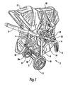
Figure 1 is a perspective view from above of a vehicle with a frame assembly and an interface portion with two child seats in a rear-facing configuration, -
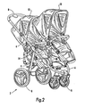
Figure 2 is a perspective view of the vehicle with the child seats in a forward-facing configuration, -
Figure 3 is a perspective view of the vehicle with the seats in the forward-facing configuration, but with all the textile materials removed, -
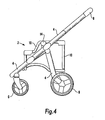
Figure 4 is a side elevation of the frame assembly of the vehicle with the interface portion, -
Figure 5 is a side elevation of only the interface portion, -
Figure 6 is an end elevation of only the interface portion, -
Figure 7 is a plan view of only the interface portion, and -
Figure 8 is a perspective view of the interface portion in a folded condition. - Referring to
Figures 1 to 4 , avehicle 2 for transporting children comprises a frame assembly 4, a plurality of ground-contactingwheels 6 attached to the frame assembly 4, and a handle 8 for grasping by the controller of the vehicle. The handle is a substantially inverted U-shaped member telescopically attached to the frame assembly 4 and a foot brake 5 is fitted to act upon the largerrear wheels 6. Thevehicle 2 also includes aninterface portion 10 which forms a sub-frame of the frame assembly 4 and which has mounted thereon, one behind the other, two child-carrying units in the form of seats 12 (with adjustable sun canopies). - The
interface portion 10 is detachably connected to the frame assembly 4 by means of conventional self-locking insert-in-socket connectors 14 at central regions of respective lateral sides of theinterface portion 10. - Referring to
Figures 5 to 7 , theinterface portion 10 is substantially rectangular in plan view (seeFigure 7 ). It has anend crossbar member 10a connected to a pair of short substantiallyvertical struts 10b, each connected to alateral bar 10c arranged substantially parallelly to each other, which are each connected to longer substantiallyvertical struts 10d extending downwardly and at their lower ends connecting to a secondend crossbar member 10e, located at substantially the same level and being of substantially the same length as theend crossbar member 10a. Eachlateral bar 10c includes a double-curved section towards the end where the shorter substantiallyvertical struts 10b are located, each double-curved section extending in respective substantially vertical planes arranged parallelly to each other. The double-curved section thereby forms two substantiallyhorizontal sections 11 and 11', the section 11' being at a higher level in the substantially vertical plane than thesection 11. Respective sections 11' also include, proximal to the double-curve section, one part of the insert-in-socket connectors 14 for connecting theinterface portion 10 to the frame assembly 4. Distal of the double-curve, the section 11' also includessockets 15 for receiving an insert of anadaptor piece 15a in a self-locking manner. Similarly, thelower section 11 includes sockets 15' for receiving the insert of anadaptor 15a'. - The adaptors used can vary depending on the type of child-carrying unit to be attached to the
interface portion 10. Thevehicle 2 shown is capable of receiving, in addition to theseats 12 shown, infant car seats and carrycots, or a combination of such units. - The
interface portion 10, in order to achieve suitable stability, is also supported at other locations on thevehicle 2, other than through theconnectors 14 mentioned above. - Referring again to
Figure 1 , thecrossbar member 10e of theinterface portion 10 has, at its central region, aclip 16 which clips onto a parallelly arranged rear crossbar of abasket frame 18, itself attached to the frame assembly 4. At the front end of theinterface portion 10,corner pieces 20 between the shorter of thevertical struts 10b and thecrossbar 10a are shaped so as to include a channel 21 (shown inFigure 6 ) in order to closely receive and rest on top of forward portions of thebasket frame 18. - Referring again to
Figures 2 and3 , theinterface portion 10 is dimensioned so as to be, when detached from the frame assembly 4, turned through 180° about its central vertical axis so that theseats 12 can, instead of being arranged in the rearward-facing configuration shown inFigure 1 , be arranged in a forward-facing configuration. In order to maintain stability of theinterface portion 10 for this seating configuration, thecrossbar member 10a also includes aclip 16 for attaching to thebasket frame 18 and also hascorner pieces 20 withchannels 21 between the longervertical struts 10d and thecrossbar 10e to closely receive and rest on top of forward portions of thebasket frame 18. - Whichever seating configuration is preferred, the
seats 12 are arranged in a compact echelon formation, theseat 12 being mounted theinterface portion 10 at section 11' in therespective sockets 15 being slightly higher than theother seat 12 mounted on thesection 11. There is also some degree of overlap between the rear part of the higher positionedseat 12 and the front part of the lower positionedseat 12, whilst still allowing a child to sit comfortably in the lower seat. Theseats 12 are also capable, as is conventional, of reclining, typically thorough an angle of approximately 45° to a substantially horizontal position in order to accommodate very young children, such as babies. Even when thehigher seat 12 is fully reclined, there is still sufficient room for a child to sit comfortably in thelower seat 12. This formation allows the vehicle to have good stability as any weight applied to eitherseat 12 is close to the centre of gravity of thevehicle 2 to prevent any dangerous tilting or toppling over of the vehicle. - Referring to
Figure 8 , theinterface portion 10 can be folded to an almost flat state for significantly reducing the volume of space occupied for storage and transportation purposes. By providing hingedcorner pieces 20 each lateral side of theinterface portion 10, comprised of one substantiallyvertical strut 10b, onelateral bar 10c and one substantiallyvertical strut 10d, is collapsible inwardly so that, in the folded state, theinterface portion 10 lies in a single plane.
Claims (15)
- A vehicle frame assembly (4) which includes an interface portion (10) having first and second mounting regions (11,11') for releasably mounting on said assembly, one behind the other, respective first and second child-carrying units (12) in an echelon formation upwardly relative to said assembly (4) wherein said interface portion (10) is a sub-frame assembly detachably connected to said frame assembly (4) characterised in that said sub-frame assembly (10) is supportedly connected to said frame assembly (4) at opposite lateral regions, at a forward region and at a rearward region of said sub-frame assembly.
- A vehicle frame assembly (4) according to claim 1, wherein said first and second mounting regions (11,11') of said interface portion (10) are arranged at different heights above the ground.
- A vehicle frame assembly (4) according to claim 1 or 2, wherein said sub-frame assembly (10) is substantially rectangular in plan view.
- A vehicle frame assembly (4) according to claim 2, or claim 3 as appended to claim 2, wherein said sub-frame assembly (10) includes a pair of lateral bars (10c) arranged substantially parallelly to each other, each lateral bar (10c) having a double-curved section which lies in a substantially vertical plane.
- A vehicle frame assembly (4) according to any preceding claim, wherein said sub-frame assembly (10) is rotatable, in the detached state, about its central vertical axis so that the child-carrying units (12) can be arranged in a forward-facing or a rearward-facing configuration.
- A vehicle frame assembly (4) according to claim 2, or any one of claims 3 to 5 as appended to claim 2, wherein the rear part of the higher positioned child-carrying unit (12) overlaps partially the front part of the lower positioned child-carrying unit (12).
- A vehicle frame assembly (4) according to any preceding claim, wherein said sub-frame assembly (10) is foldable to lie in a single plane.
- A vehicle frame assembly (4) according to any preceding claim, wherein said sub-frame assembly (10) comprises respective clips (16) at the forward and rearward regions and connectors (14) at respective lateral sides for supportingly attaching said sub-frame assembly (10) to said frame assembly (4).
- A vehicle frame assembly (4) according to claim 8, wherein said forward region of said sub-frame (10) further comprises respective corner pieces (20) which include channels (21) which are further supportingly received by said frame assembly.
- A vehicle frame assembly (4) according to claim 8 or 9, wherein said sub-frame assembly (10) is supported at the forward and rearward regions by a basket frame (18) of said frame assembly (4).
- A method of mounting first and second child-carrying units (12) one behind the other, in an echelon formation upwardly, on a vehicle frame assembly (4), comprising mounting on a first mounting region (11) of an interface portion (10) of said assembly (4) the first child-carrying unit (12) and mounting on a second mounting region (11') of said interface portion (10) the second child-carrying unit (12) at a higher level than the first unit (12), wherein said interface portion (10) is a sub-frame assembly for detachably connecting to said frame assembly (4) characterised in that said sub-frame assembly (10) is supportedly connected to said frame assembly (4) at opposite lateral regions, at a forward region and at a rearward region of said sub-frame assembly (10).
- A method according to claim 11, wherein said supporting comprises connecting respective connectors (14) at respective lateral sides of said sub-frame assembly (10) and respective clips (16) at said forward and rearward regions of said sub-frame assembly (10) to said frame assembly (4).
- A method according to claim 12, and further comprising receiving said frame assembly (4) in channels (21) formed in respective corner pieces (20) of said forward region of said sub-frame assembly (10).
- A method according to any one of claims 11 to 13, and further comprising, in the detached state, rotating said sub-frame assembly (10) about its central vertical axis for a forward-facing or a rearward-facing configuration of the child-carrying units (12).
- A method according to claim 14, and in the detached state, folding said interface portion (10) so as to lie in a single plane.
Applications Claiming Priority (2)
| Application Number | Priority Date | Filing Date | Title |
|---|---|---|---|
| GBGB0619755.2A GB0619755D0 (en) | 2006-10-06 | 2006-10-06 | Apparatus and method |
| PCT/EP2007/060590 WO2008040797A1 (en) | 2006-10-06 | 2007-10-05 | Vehicle frame assembly |
Publications (2)
| Publication Number | Publication Date |
|---|---|
| EP2071921A1 EP2071921A1 (en) | 2009-06-24 |
| EP2071921B1 true EP2071921B1 (en) | 2012-01-11 |
Family
ID=37454081
Family Applications (1)
| Application Number | Title | Priority Date | Filing Date |
|---|---|---|---|
| EP07820964A Not-in-force EP2071921B1 (en) | 2006-10-06 | 2007-10-05 | Vehicle frame assembly |
Country Status (12)
| Country | Link |
|---|---|
| US (1) | US20100072732A1 (en) |
| EP (1) | EP2071921B1 (en) |
| JP (1) | JP2010505688A (en) |
| CN (1) | CN101588954B (en) |
| AT (1) | ATE540848T1 (en) |
| AU (1) | AU2007304150B2 (en) |
| CA (1) | CA2665513A1 (en) |
| DE (1) | DE07820964T1 (en) |
| GB (1) | GB0619755D0 (en) |
| NO (1) | NO20091773L (en) |
| RU (1) | RU2441790C2 (en) |
| WO (1) | WO2008040797A1 (en) |
Families Citing this family (20)
| Publication number | Priority date | Publication date | Assignee | Title |
|---|---|---|---|---|
| US8371606B2 (en) | 2007-04-13 | 2013-02-12 | Phil And Teds Most Excellent Buggy Company Limited | Collapsible two seat perambulator |
| US20100013281A1 (en) * | 2008-07-16 | 2010-01-21 | Hung-Tsun Chen | Dual-seat frame of baby stroller |
| GB0818605D0 (en) | 2008-10-10 | 2008-11-19 | Scs London Ltd | Apparatus and method |
| AU2009328630B2 (en) * | 2008-12-19 | 2014-04-17 | Britax Childcare Pty Ltd | Folding stroller improvements |
| US8505958B2 (en) | 2009-03-25 | 2013-08-13 | Kolcraft Enterprises, Inc. | Sit or stand strollers and methods of making the same |
| DE202009005213U1 (en) | 2009-08-31 | 2009-12-24 | Beger, Udo | Pushcars for children and / or dolls |
| US8584770B2 (en) | 2010-03-23 | 2013-11-19 | Black & Decker Inc. | Spindle bearing arrangement for a power tool |
| US20120067373A1 (en) * | 2010-04-15 | 2012-03-22 | Philip Frank Souter | Automatic Dishwashing Detergent Composition |
| ES2396886B1 (en) * | 2011-01-03 | 2014-01-20 | Jane, S.A. | Chassis for strollers with two seats. |
| CN102632916B (en) * | 2012-04-16 | 2014-07-02 | 中山市隆成日用制品有限公司 | Dual-base baby carriage capable of converting base direction and pattern |
| FR2991957B1 (en) * | 2012-06-18 | 2014-12-12 | Dorel France Sa | MULTI-SEAT SUPPORT DEVICE FOR A CHILD CAR |
| US20160128491A1 (en) * | 2013-07-12 | 2016-05-12 | The University Of Sydney | A combination of child carrier and stroller |
| US9889872B2 (en) * | 2016-03-28 | 2018-02-13 | Ignio LLC | Multi-function mobility device |
| US9849903B1 (en) * | 2016-12-09 | 2017-12-26 | Tung Tzu Industrial Co., Ltd. | Assembling structure of double stroller |
| EP3363711A1 (en) * | 2017-02-14 | 2018-08-22 | Dorel France | Child's pushchair comprising a removable booster seat, and corresponding booster seat |
| NL2019522B1 (en) * | 2017-09-11 | 2019-03-19 | Maxi Miliaan Bv | Set for transporting at least one child, a stroller and a carrying device suitable for such a set |
| CN112203921B (en) * | 2017-09-13 | 2023-02-28 | 康贝株式会社 | Baby carriage |
| EP3766781B1 (en) * | 2019-07-14 | 2024-05-15 | Goodrich Lighting Systems GmbH | Passenger seat canopy |
| JP2022549108A (en) | 2019-09-18 | 2022-11-24 | サイベックス ゲーエムベーハー | strollers and stroller frames |
| US12594979B2 (en) | 2021-09-13 | 2026-04-07 | Artsana Usa, Inc. | Folding stroller adaptable for single or double occupants |
Family Cites Families (14)
| Publication number | Priority date | Publication date | Assignee | Title |
|---|---|---|---|---|
| GB2193692B (en) * | 1986-07-15 | 1991-02-20 | David Alick Burgoyne | Single and or double infant carriage |
| JPH072177U (en) * | 1992-11-24 | 1995-01-13 | 文 暉 安 | Safety chair and baby carriage |
| ES1033012Y (en) * | 1996-01-16 | 1996-12-01 | Jane Sa | TWO-SEAT CHILDREN'S CAR-CHAIR. |
| US5722682A (en) * | 1996-06-27 | 1998-03-03 | Wang; Morgan | Foldable two-seater stroller |
| US5865447A (en) * | 1997-03-17 | 1999-02-02 | Huang; Li-Chu Chen | Controlling structure of a stroller |
| DE29814902U1 (en) * | 1998-08-20 | 1998-10-01 | Britax-Teutonia Kinderwagenfabrik GmbH, 32120 Hiddenhausen | Twin or sibling |
| RU2163205C1 (en) * | 1999-10-25 | 2001-02-20 | Государственное унитарное предприятие Вольский механический завод | Folding baby carriage |
| US6209892B1 (en) * | 1999-12-14 | 2001-04-03 | William Chester Schaaf | Baby stroller apparatus for use in combination with a standard child's car seat |
| JP2002087277A (en) * | 2000-09-20 | 2002-03-27 | Toyota Industries Corp | Stroller |
| US6702316B2 (en) * | 2001-10-18 | 2004-03-09 | Ben M. Hsia | Stroller with car seat fastening arrangement |
| US6843498B2 (en) * | 2002-06-06 | 2005-01-18 | Kolcraft Enterprises, Inc. | Stroller |
| US7597332B2 (en) * | 2003-09-02 | 2009-10-06 | Hatch Design, Inc. | Modular stroller |
| US7017937B2 (en) * | 2003-10-30 | 2006-03-28 | Williams Michael D | Double occupancy baby stroller |
| TWM290119U (en) * | 2005-10-14 | 2006-05-01 | Link Treasure Ltd | Framework structure of stroller |
-
2006
- 2006-10-06 GB GBGB0619755.2A patent/GB0619755D0/en not_active Ceased
-
2007
- 2007-10-05 EP EP07820964A patent/EP2071921B1/en not_active Not-in-force
- 2007-10-05 WO PCT/EP2007/060590 patent/WO2008040797A1/en not_active Ceased
- 2007-10-05 JP JP2009530898A patent/JP2010505688A/en active Pending
- 2007-10-05 DE DE07820964T patent/DE07820964T1/en active Pending
- 2007-10-05 US US12/311,485 patent/US20100072732A1/en not_active Abandoned
- 2007-10-05 AT AT07820964T patent/ATE540848T1/en active
- 2007-10-05 AU AU2007304150A patent/AU2007304150B2/en not_active Ceased
- 2007-10-05 CA CA002665513A patent/CA2665513A1/en not_active Abandoned
- 2007-10-05 CN CN2007800373202A patent/CN101588954B/en not_active Expired - Fee Related
- 2007-10-05 RU RU2009116774/11A patent/RU2441790C2/en not_active IP Right Cessation
-
2009
- 2009-05-05 NO NO20091773A patent/NO20091773L/en not_active Application Discontinuation
Also Published As
| Publication number | Publication date |
|---|---|
| CN101588954B (en) | 2012-09-05 |
| CA2665513A1 (en) | 2008-04-10 |
| EP2071921A1 (en) | 2009-06-24 |
| RU2441790C2 (en) | 2012-02-10 |
| JP2010505688A (en) | 2010-02-25 |
| AU2007304150B2 (en) | 2012-09-27 |
| CN101588954A (en) | 2009-11-25 |
| ATE540848T1 (en) | 2012-01-15 |
| DE07820964T1 (en) | 2009-09-17 |
| NO20091773L (en) | 2009-05-05 |
| AU2007304150A2 (en) | 2010-09-02 |
| WO2008040797A1 (en) | 2008-04-10 |
| US20100072732A1 (en) | 2010-03-25 |
| RU2009116774A (en) | 2010-11-20 |
| GB0619755D0 (en) | 2006-11-15 |
| AU2007304150A1 (en) | 2008-04-10 |
Similar Documents
| Publication | Publication Date | Title |
|---|---|---|
| AU2007304150B2 (en) | Vehicle frame assembly | |
| JP2010505688A5 (en) | ||
| US8602441B2 (en) | Tandem stroller | |
| CN105383538B (en) | Stroller device | |
| US6270093B1 (en) | Multiple child seat nestable shopping cart | |
| US4620711A (en) | Multi-function child carrier | |
| US6585284B2 (en) | Child stroller with height-adjustable rear seat | |
| EP0630798A1 (en) | Pushchair | |
| EP2895378B1 (en) | Stroller | |
| EP0637290B1 (en) | Push-chair | |
| CN101426678A (en) | Carriage for carrying children | |
| GB2474547A (en) | A stroller adapted to carry a car child seat | |
| US20230078130A1 (en) | Folding stroller adaptable for single or double occupants | |
| US6938906B1 (en) | Baby stroller with engageable locking device | |
| CN215663603U (en) | Children's barrow | |
| EP0519857B1 (en) | Seat for children's pushchair | |
| CN104334437B (en) | Support means for multiple seats of stroller | |
| EP0257141B1 (en) | Multi-function child carrier | |
| CN109278838B (en) | Strollers | |
| CN113276931A (en) | Children's barrow | |
| KR102464139B1 (en) | A Stroller Compatible with Car seat | |
| US20030122352A1 (en) | Device for mounting accessory wheels on stroller | |
| CN201257991Y (en) | Perambulator | |
| WO2003020568A1 (en) | Carrier aid for fitting to a pram or pushchair | |
| CN121448489A (en) | Carrier tool |
Legal Events
| Date | Code | Title | Description |
|---|---|---|---|
| PUAI | Public reference made under article 153(3) epc to a published international application that has entered the european phase |
Free format text: ORIGINAL CODE: 0009012 |
|
| 17P | Request for examination filed |
Effective date: 20090423 |
|
| AK | Designated contracting states |
Kind code of ref document: A1 Designated state(s): AT BE BG CH CY CZ DE DK EE ES FI FR GB GR HU IE IS IT LI LT LU LV MC MT NL PL PT RO SE SI SK TR |
|
| DET | De: translation of patent claims | ||
| 17Q | First examination report despatched |
Effective date: 20091009 |
|
| GRAP | Despatch of communication of intention to grant a patent |
Free format text: ORIGINAL CODE: EPIDOSNIGR1 |
|
| DAX | Request for extension of the european patent (deleted) | ||
| GRAS | Grant fee paid |
Free format text: ORIGINAL CODE: EPIDOSNIGR3 |
|
| GRAA | (expected) grant |
Free format text: ORIGINAL CODE: 0009210 |
|
| AK | Designated contracting states |
Kind code of ref document: B1 Designated state(s): AT BE BG CH CY CZ DE DK EE ES FI FR GB GR HU IE IS IT LI LT LU LV MC MT NL PL PT RO SE SI SK TR |
|
| REG | Reference to a national code |
Ref country code: GB Ref legal event code: FG4D |
|
| REG | Reference to a national code |
Ref country code: CH Ref legal event code: EP |
|
| REG | Reference to a national code |
Ref country code: AT Ref legal event code: REF Ref document number: 540848 Country of ref document: AT Kind code of ref document: T Effective date: 20120115 |
|
| REG | Reference to a national code |
Ref country code: IE Ref legal event code: FG4D |
|
| REG | Reference to a national code |
Ref country code: DE Ref legal event code: R096 Ref document number: 602007020035 Country of ref document: DE Effective date: 20120315 |
|
| REG | Reference to a national code |
Ref country code: NL Ref legal event code: VDEP Effective date: 20120111 |
|
| PG25 | Lapsed in a contracting state [announced via postgrant information from national office to epo] |
Ref country code: SI Free format text: LAPSE BECAUSE OF FAILURE TO SUBMIT A TRANSLATION OF THE DESCRIPTION OR TO PAY THE FEE WITHIN THE PRESCRIBED TIME-LIMIT Effective date: 20120111 |
|
| LTIE | Lt: invalidation of european patent or patent extension |
Effective date: 20120111 |
|
| PG25 | Lapsed in a contracting state [announced via postgrant information from national office to epo] |
Ref country code: NL Free format text: LAPSE BECAUSE OF FAILURE TO SUBMIT A TRANSLATION OF THE DESCRIPTION OR TO PAY THE FEE WITHIN THE PRESCRIBED TIME-LIMIT Effective date: 20120111 Ref country code: IS Free format text: LAPSE BECAUSE OF FAILURE TO SUBMIT A TRANSLATION OF THE DESCRIPTION OR TO PAY THE FEE WITHIN THE PRESCRIBED TIME-LIMIT Effective date: 20120511 Ref country code: BG Free format text: LAPSE BECAUSE OF FAILURE TO SUBMIT A TRANSLATION OF THE DESCRIPTION OR TO PAY THE FEE WITHIN THE PRESCRIBED TIME-LIMIT Effective date: 20120411 Ref country code: BE Free format text: LAPSE BECAUSE OF FAILURE TO SUBMIT A TRANSLATION OF THE DESCRIPTION OR TO PAY THE FEE WITHIN THE PRESCRIBED TIME-LIMIT Effective date: 20120111 Ref country code: LT Free format text: LAPSE BECAUSE OF FAILURE TO SUBMIT A TRANSLATION OF THE DESCRIPTION OR TO PAY THE FEE WITHIN THE PRESCRIBED TIME-LIMIT Effective date: 20120111 |
|
| PG25 | Lapsed in a contracting state [announced via postgrant information from national office to epo] |
Ref country code: GR Free format text: LAPSE BECAUSE OF FAILURE TO SUBMIT A TRANSLATION OF THE DESCRIPTION OR TO PAY THE FEE WITHIN THE PRESCRIBED TIME-LIMIT Effective date: 20120412 Ref country code: LV Free format text: LAPSE BECAUSE OF FAILURE TO SUBMIT A TRANSLATION OF THE DESCRIPTION OR TO PAY THE FEE WITHIN THE PRESCRIBED TIME-LIMIT Effective date: 20120111 Ref country code: FI Free format text: LAPSE BECAUSE OF FAILURE TO SUBMIT A TRANSLATION OF THE DESCRIPTION OR TO PAY THE FEE WITHIN THE PRESCRIBED TIME-LIMIT Effective date: 20120111 Ref country code: PL Free format text: LAPSE BECAUSE OF FAILURE TO SUBMIT A TRANSLATION OF THE DESCRIPTION OR TO PAY THE FEE WITHIN THE PRESCRIBED TIME-LIMIT Effective date: 20120111 Ref country code: PT Free format text: LAPSE BECAUSE OF FAILURE TO SUBMIT A TRANSLATION OF THE DESCRIPTION OR TO PAY THE FEE WITHIN THE PRESCRIBED TIME-LIMIT Effective date: 20120511 |
|
| REG | Reference to a national code |
Ref country code: AT Ref legal event code: MK05 Ref document number: 540848 Country of ref document: AT Kind code of ref document: T Effective date: 20120111 |
|
| PG25 | Lapsed in a contracting state [announced via postgrant information from national office to epo] |
Ref country code: CY Free format text: LAPSE BECAUSE OF FAILURE TO SUBMIT A TRANSLATION OF THE DESCRIPTION OR TO PAY THE FEE WITHIN THE PRESCRIBED TIME-LIMIT Effective date: 20120111 |
|
| PG25 | Lapsed in a contracting state [announced via postgrant information from national office to epo] |
Ref country code: CZ Free format text: LAPSE BECAUSE OF FAILURE TO SUBMIT A TRANSLATION OF THE DESCRIPTION OR TO PAY THE FEE WITHIN THE PRESCRIBED TIME-LIMIT Effective date: 20120111 Ref country code: DK Free format text: LAPSE BECAUSE OF FAILURE TO SUBMIT A TRANSLATION OF THE DESCRIPTION OR TO PAY THE FEE WITHIN THE PRESCRIBED TIME-LIMIT Effective date: 20120111 Ref country code: EE Free format text: LAPSE BECAUSE OF FAILURE TO SUBMIT A TRANSLATION OF THE DESCRIPTION OR TO PAY THE FEE WITHIN THE PRESCRIBED TIME-LIMIT Effective date: 20120111 Ref country code: RO Free format text: LAPSE BECAUSE OF FAILURE TO SUBMIT A TRANSLATION OF THE DESCRIPTION OR TO PAY THE FEE WITHIN THE PRESCRIBED TIME-LIMIT Effective date: 20120111 Ref country code: SE Free format text: LAPSE BECAUSE OF FAILURE TO SUBMIT A TRANSLATION OF THE DESCRIPTION OR TO PAY THE FEE WITHIN THE PRESCRIBED TIME-LIMIT Effective date: 20120111 |
|
| PLBE | No opposition filed within time limit |
Free format text: ORIGINAL CODE: 0009261 |
|
| STAA | Information on the status of an ep patent application or granted ep patent |
Free format text: STATUS: NO OPPOSITION FILED WITHIN TIME LIMIT |
|
| PG25 | Lapsed in a contracting state [announced via postgrant information from national office to epo] |
Ref country code: SK Free format text: LAPSE BECAUSE OF FAILURE TO SUBMIT A TRANSLATION OF THE DESCRIPTION OR TO PAY THE FEE WITHIN THE PRESCRIBED TIME-LIMIT Effective date: 20120111 Ref country code: IT Free format text: LAPSE BECAUSE OF FAILURE TO SUBMIT A TRANSLATION OF THE DESCRIPTION OR TO PAY THE FEE WITHIN THE PRESCRIBED TIME-LIMIT Effective date: 20120111 |
|
| 26N | No opposition filed |
Effective date: 20121012 |
|
| PG25 | Lapsed in a contracting state [announced via postgrant information from national office to epo] |
Ref country code: AT Free format text: LAPSE BECAUSE OF FAILURE TO SUBMIT A TRANSLATION OF THE DESCRIPTION OR TO PAY THE FEE WITHIN THE PRESCRIBED TIME-LIMIT Effective date: 20120111 |
|
| REG | Reference to a national code |
Ref country code: DE Ref legal event code: R097 Ref document number: 602007020035 Country of ref document: DE Effective date: 20121012 |
|
| PG25 | Lapsed in a contracting state [announced via postgrant information from national office to epo] |
Ref country code: ES Free format text: LAPSE BECAUSE OF FAILURE TO SUBMIT A TRANSLATION OF THE DESCRIPTION OR TO PAY THE FEE WITHIN THE PRESCRIBED TIME-LIMIT Effective date: 20120422 |
|
| PG25 | Lapsed in a contracting state [announced via postgrant information from national office to epo] |
Ref country code: MC Free format text: LAPSE BECAUSE OF NON-PAYMENT OF DUE FEES Effective date: 20121031 |
|
| REG | Reference to a national code |
Ref country code: CH Ref legal event code: PL |
|
| REG | Reference to a national code |
Ref country code: IE Ref legal event code: MM4A |
|
| PG25 | Lapsed in a contracting state [announced via postgrant information from national office to epo] |
Ref country code: LI Free format text: LAPSE BECAUSE OF NON-PAYMENT OF DUE FEES Effective date: 20121031 Ref country code: IE Free format text: LAPSE BECAUSE OF NON-PAYMENT OF DUE FEES Effective date: 20121005 Ref country code: CH Free format text: LAPSE BECAUSE OF NON-PAYMENT OF DUE FEES Effective date: 20121031 |
|
| PG25 | Lapsed in a contracting state [announced via postgrant information from national office to epo] |
Ref country code: MT Free format text: LAPSE BECAUSE OF FAILURE TO SUBMIT A TRANSLATION OF THE DESCRIPTION OR TO PAY THE FEE WITHIN THE PRESCRIBED TIME-LIMIT Effective date: 20120111 |
|
| PG25 | Lapsed in a contracting state [announced via postgrant information from national office to epo] |
Ref country code: TR Free format text: LAPSE BECAUSE OF FAILURE TO SUBMIT A TRANSLATION OF THE DESCRIPTION OR TO PAY THE FEE WITHIN THE PRESCRIBED TIME-LIMIT Effective date: 20120111 |
|
| PG25 | Lapsed in a contracting state [announced via postgrant information from national office to epo] |
Ref country code: LU Free format text: LAPSE BECAUSE OF NON-PAYMENT OF DUE FEES Effective date: 20121005 |
|
| PG25 | Lapsed in a contracting state [announced via postgrant information from national office to epo] |
Ref country code: HU Free format text: LAPSE BECAUSE OF FAILURE TO SUBMIT A TRANSLATION OF THE DESCRIPTION OR TO PAY THE FEE WITHIN THE PRESCRIBED TIME-LIMIT Effective date: 20071005 |
|
| PGFP | Annual fee paid to national office [announced via postgrant information from national office to epo] |
Ref country code: GB Payment date: 20141028 Year of fee payment: 8 Ref country code: DE Payment date: 20141204 Year of fee payment: 8 Ref country code: FR Payment date: 20141028 Year of fee payment: 8 |
|
| REG | Reference to a national code |
Ref country code: DE Ref legal event code: R119 Ref document number: 602007020035 Country of ref document: DE |
|
| GBPC | Gb: european patent ceased through non-payment of renewal fee |
Effective date: 20151005 |
|
| PG25 | Lapsed in a contracting state [announced via postgrant information from national office to epo] |
Ref country code: DE Free format text: LAPSE BECAUSE OF NON-PAYMENT OF DUE FEES Effective date: 20160503 Ref country code: GB Free format text: LAPSE BECAUSE OF NON-PAYMENT OF DUE FEES Effective date: 20151005 |
|
| REG | Reference to a national code |
Ref country code: FR Ref legal event code: ST Effective date: 20160630 |
|
| PG25 | Lapsed in a contracting state [announced via postgrant information from national office to epo] |
Ref country code: FR Free format text: LAPSE BECAUSE OF NON-PAYMENT OF DUE FEES Effective date: 20151102 |