EP2071930B1 - Actionnement d'une bifurcation de moteur à réacteur à double flux pour modifier une zone effective de sortie de tuyère - Google Patents
Actionnement d'une bifurcation de moteur à réacteur à double flux pour modifier une zone effective de sortie de tuyère Download PDFInfo
- Publication number
- EP2071930B1 EP2071930B1 EP06851722A EP06851722A EP2071930B1 EP 2071930 B1 EP2071930 B1 EP 2071930B1 EP 06851722 A EP06851722 A EP 06851722A EP 06851722 A EP06851722 A EP 06851722A EP 2071930 B1 EP2071930 B1 EP 2071930B1
- Authority
- EP
- European Patent Office
- Prior art keywords
- bypass flow
- nacelle
- flow path
- exit area
- core
- Prior art date
- Legal status (The legal status is an assumption and is not a legal conclusion. Google has not performed a legal analysis and makes no representation as to the accuracy of the status listed.)
- Active
Links
Images

Classifications
-
- F—MECHANICAL ENGINEERING; LIGHTING; HEATING; WEAPONS; BLASTING
- F02—COMBUSTION ENGINES; HOT-GAS OR COMBUSTION-PRODUCT ENGINE PLANTS
- F02K—JET-PROPULSION PLANTS
- F02K3/00—Plants including a gas turbine driving a compressor or a ducted fan
- F02K3/02—Plants including a gas turbine driving a compressor or a ducted fan in which part of the working fluid by-passes the turbine and combustion chamber
- F02K3/04—Plants including a gas turbine driving a compressor or a ducted fan in which part of the working fluid by-passes the turbine and combustion chamber the plant including ducted fans, i.e. fans with high volume, low pressure outputs, for augmenting the jet thrust, e.g. of double-flow type
- F02K3/075—Plants including a gas turbine driving a compressor or a ducted fan in which part of the working fluid by-passes the turbine and combustion chamber the plant including ducted fans, i.e. fans with high volume, low pressure outputs, for augmenting the jet thrust, e.g. of double-flow type controlling flow ratio between flows
-
- F—MECHANICAL ENGINEERING; LIGHTING; HEATING; WEAPONS; BLASTING
- F01—MACHINES OR ENGINES IN GENERAL; ENGINE PLANTS IN GENERAL; STEAM ENGINES
- F01D—NON-POSITIVE DISPLACEMENT MACHINES OR ENGINES, e.g. STEAM TURBINES
- F01D17/00—Regulating or controlling by varying flow
- F01D17/10—Final actuators
- F01D17/12—Final actuators arranged in stator parts
- F01D17/14—Final actuators arranged in stator parts varying effective cross-sectional area of nozzles or guide conduits
- F01D17/141—Final actuators arranged in stator parts varying effective cross-sectional area of nozzles or guide conduits by means of shiftable members or valves obturating part of the flow path
-
- F—MECHANICAL ENGINEERING; LIGHTING; HEATING; WEAPONS; BLASTING
- F02—COMBUSTION ENGINES; HOT-GAS OR COMBUSTION-PRODUCT ENGINE PLANTS
- F02K—JET-PROPULSION PLANTS
- F02K1/00—Plants characterised by the form or arrangement of the jet pipe or nozzle; Jet pipes or nozzles peculiar thereto
- F02K1/06—Varying effective area of jet pipe or nozzle
- F02K1/12—Varying effective area of jet pipe or nozzle by means of pivoted flaps
Definitions
- This invention relates to an apparatus and method for changing an effective nozzle exit area of a turbofan engine.
- a typical turbofan engine includes a core nacelle housing one or more spools supporting at least one compressor and turbine. One of the spools is used to rotationally drive a turbofan arranged upstream from the core nacelle.
- a fan nacelle surrounds the turbofan and the core nacelle.
- the core nacelle is supported by several bifurcations to centrally locate the core nacelle relative to the fan nacelle.
- the bifurcations are used to house various components, such as bleed air conduits and wires, for example.
- the bifurcations are typically fixed, closed structures.
- a generally annular bypass flow path is arranged between the core and fan nacelles through which bypass air from the turbofan flows.
- the bifurcations are arranged in the bypass flow path.
- the bypass flow exits from a nozzle exit area at the rear of the engine.
- the nozzle exit area is typically fixed in a turbofan engine.
- Non-turbofan aircraft turbine engines have been developed that change the effective nozzle exit area to affect the efficiency and operation of the engine.
- multiple circumferentially arranged flaps at the exit of the engine nozzle are rotated inwardly and outwardly in a radial direction to change the physical size of the nozzle's exit area.
- This arrangement adds additional weight and cost to the engine externals.
- Many flaps are required as well as associated actuators. Further, the moveable flaps are external and subject to damage from foreign objects.
- turbofan engine capable of changing the effective nozzle exit area using existing engine structure and surfaces.
- a turbine engine having the features of the preamble of claim 1 is disclosed in WO 03/060312 .
- the invention provides a turbine engine as set forth in claim 1.
- Opposing surfaces are supported relative to the bifurcation and are moveable between closed and open positions to selectively obstruct bypass flow through the bypass flow path, thereby changing the effective area of the nozzle.
- a change in the effective area of the nozzle can be used to improve the efficiency and operation of the turbine engine.
- the opposing surfaces are manipulated in generally circumferential and axial directions about one or more pivots in an arc in response to a controller commanding an actuator under predetermined conditions.
- a geared turbofan engine 10 is shown in Figure 1 .
- a pylon 38 secures the engine 10 to an aircraft.
- the engine 10 includes a core nacelle 12 that houses a low spool 14 and high spool 24 rotatable about an axis A.
- the low spool 14 supports a low pressure compressor 16 and low pressure turbine 18.
- the low spool 14 drives a turbofan 20 through a gear train 22.
- the high spool 24 supports a high pressure compressor 26 and high pressure turbine 28.
- a combustor 30 is arranged between the high pressure compressor 26 and high pressure turbine 28. Compressed air from compressors 16, 26 mixes with fuel from the combustor 30 and is expanded in turbines 18, 28.
- the engine 10 is a high bypass turbofan arrangement.
- the bypass ratio is greater than 10:1
- the turbofan diameter is substantially larger than the diameter of the low pressure compressor 16.
- the low pressure turbine 18 has a pressure ratio that is greater than 5:1, in one example.
- the gear train 22 is an epicycle gear train, for examples, a star gear train providing a gear reduction ratio of greater than 2.5:1. It should be understood, however, that the above parameters are only exemplary of a contemplated geared turbofan engine. That is, the invention is applicable to other engines including direct drive turbofans.
- the turbofan 20 directs air into the core nacelle 12, which is used to drive the turbines 18, 28, as is known in the art.
- Turbine exhaust E exits the core nacelle 12 once it has been expanded in the turbines 18, 28, in a passage provided between the core nacelle and a tail cone 32.
- the core nacelle 12 is supported within the fan nacelle 34 by structure 36, which are commonly referred to as upper and lower bifurcations.
- a generally annular bypass flow path 39 is arranged between the core and fan nacelles 12, 34.
- the example illustrated in Figure 1 depicts a high bypass flow arrangement in which approximately eighty percent of the airflow entering the fan nacelle 34 bypasses the core nacelle 12.
- the bypass flow B within the bypass flow path 39 exits the fan nacelle 34 through a nozzle exit area 40.
- Thrust is a function of density, velocity and area. One or more of these parameters can be manipulated to vary the amount and direction of thrust provided by the bypass flow B.
- the engine 10 includes a structure associated with the nozzle exit area 40 to change the physical area and geometry to manipulate the thrust provided by the bypass flow B.
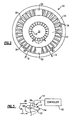
- the engine 10 has a flow control device 41 ( Figure 3 ) that is used to effectively change the nozzle exit area.
- the flow control device 41 provides the fan nozzle exit area 40 for discharging axially the bypass flow B pressurized by the upstream turbofan 20 of the engine 10. A significant amount of thrust is provided by the bypass flow B due to the high bypass ratio.
- the turbofan 20 of the engine 10 is designed for a particular flight condition, typically cruise at 0.8M and 35,000 feet.
- the turbofan 20 is designed at a particular fixed stagger angle for an efficient cruise condition.
- the flow control device 41 is operated to vary the nozzle exit area 40 to adjust fan bypass air flow such that the angle of attack or incidence on the fan blade is maintained close to design incidence at other flight conditions, such as landing and takeoff.
- the flow control device 41 defines a nominal converged position for the nozzle exit area 40 at cruise and climb conditions, and radially opens relative thereto to define a diverged position for other flight conditions.
- the flow control device 41 provides an approximately 20% change in the exit nozzle area 40.
- opposing bifurcations 52 radially extend between the core and fan nacelles 12, 34 to support the core nacelle 12 relative to the fan nacelle 34.
- bleed lines and other connections are housed within the bifurcations 52 to connect the core nacelle 12 and its components with other areas of the aircraft.
- the bifurcations 52 are arranged inside the fan nacelle 34 and are not exposed to potentially destructive foreign objects.
- the flow control device 41 is used to change the effective nozzle exit area, although the nozzle exit area 40 is fixed. In the examples shown, this is achieved by moving one or more surfaces supported, for example, by the bifurcation 52 to selectively obstruct portions of the bypass flow B through the bypass flow path 39.
- opposing surfaces 56 connected to the bifurcations 52 by pivots 54 near a trailing edge of the bifurcation 52 are moved by an actuator 58 between closed and open positions C, O.
- the pivot 54 is arranged on one end of opposing ends of each surface 56.
- a single actuator is shown schematically connected to the surfaces 56 by linkages. However, other configurations can be used.
- the surfaces 56 move in an arc in generally axial and circumferential directions in the examples shown.
- the actuator 58 is commanded by a controller 60 under predetermined conditions to change the effective nozzle exit area with the surfaces 56 to improve the efficiency and operation of the turbine engine 10..
- control device 41 uses surfaces of existing engine structures in the turbine engine to minimize the additional weight and cost associated with providing a change in the effective nozzle exit area.
Landscapes
- Engineering & Computer Science (AREA)
- Mechanical Engineering (AREA)
- General Engineering & Computer Science (AREA)
- Chemical & Material Sciences (AREA)
- Combustion & Propulsion (AREA)
- Control Of Turbines (AREA)
- Structures Of Non-Positive Displacement Pumps (AREA)
Abstract
Claims (7)
- Turbomoteur (10) comprenant :un corps (14) supportant une turbine (18) ;un turbofan (20) agencé en amont d'une nacelle centrale (12) et accouplé au corps ;une nacelle de soufflante (34) entourant le turbofan (20) et fournissant un chemin d'écoulement de dérivation (39) entre les nacelles de soufflante et centrale, ayant une surface de sortie de tuyère ;un dispositif de régulation de l'écoulement (41) incluant une surface dans le chemin d'écoulement de dérivation (39), déplaçable entre des positions fermée et ouverte pour modifier efficacement la surface de sortie de tuyère (40) ; etune bifurcation (52) s'étendant entre les nacelles centrale et de soufflante (12, 34) pour supporter la nacelle centrale (12) par rapport à la nacelle de soufflante (34), la surface (56) étant supportée sur la bifurcation (52), la bifurcation (52) supportant des surfaces opposées (56) sur des côtés opposés de la bifurcation (52), chacune des surfaces opposées (56) ayant des bords d'attaque et de fuite, caractérisé en ce que chaque surface opposée est déplaçable autour d'un pivot (54) à proximité du bord de fuite entre les positions fermée et ouverte dans une direction généralement circonférentielle.
- Turbomoteur selon la revendication 1, dans lequel le dispositif de régulation de l'écoulement (41) comporte un régulateur (61) programmé pour amorcer le mouvement des surfaces (56) entre les positions fermée et ouverte en réponse à un état prédéterminé.
- Turbomoteur selon la revendication 2, dans lequel le dispositif de régulation de l'écoulement (41) comporte un actionneur (58) relié aux surfaces (56) et communiquant avec le régulateur (60), l'actionneur (58) étant prévu pour recevoir une commande du régulateur (60) en réponse à l'état prédéterminé.
- Procédé pour modifier la surface de sortie de tuyère efficace (40) d'un turbomoteur selon la revendication 1, comprenant les étapes consistant à :a) fournir un chemin d'écoulement de dérivation (39) contournant une nacelle centrale ; etb) déplacer des surfaces opposées (56) dans le chemin d'écoulement de dérivation (39) en utilisant un actionneur unique (58) connecté fonctionnellement aux surfaces opposées (56) pour modifier efficacement une surface de sortie de tuyère (40) associée au chemin d'écoulement de dérivation (39).
- Procédé selon la revendication 4, dans lequel l'étape b) comporte le déplacement des surfaces (56) entre des positions ouverte et fermée en réponse à un état prédéterminé.
- Procédé selon la revendication 5, dans lequel l'étape b) comporte l'obstruction partielle du chemin d'écoulement de dérivation (39) avec les surfaces (56) dans la position ouverte.
- Procédé selon la revendication 6, dans lequel l'étape b) comporte le déplacement des surfaces opposées (56) à l'écart l'une de l'autre lors du déplacement de la position fermée dans la position ouverte.
Applications Claiming Priority (1)
| Application Number | Priority Date | Filing Date | Title |
|---|---|---|---|
| PCT/US2006/039802 WO2008045053A2 (fr) | 2006-10-12 | 2006-10-12 | Actionnement d'une bifurcation de moteur à réacteur à double flux pour modifier une zone effective de sortie de tuyère |
Publications (2)
| Publication Number | Publication Date |
|---|---|
| EP2071930A2 EP2071930A2 (fr) | 2009-06-24 |
| EP2071930B1 true EP2071930B1 (fr) | 2012-06-27 |
Family
ID=39283309
Family Applications (1)
| Application Number | Title | Priority Date | Filing Date |
|---|---|---|---|
| EP06851722A Active EP2071930B1 (fr) | 2006-10-12 | 2006-10-12 | Actionnement d'une bifurcation de moteur à réacteur à double flux pour modifier une zone effective de sortie de tuyère |
Country Status (3)
| Country | Link |
|---|---|
| US (1) | US8137060B2 (fr) |
| EP (1) | EP2071930B1 (fr) |
| WO (1) | WO2008045053A2 (fr) |
Families Citing this family (13)
| Publication number | Priority date | Publication date | Assignee | Title |
|---|---|---|---|---|
| GB0700238D0 (en) | 2007-01-06 | 2007-02-14 | Rolls Royce Plc | Nozzle arrangement |
| DE112007001683T5 (de) * | 2007-01-17 | 2010-01-07 | United Technologies Corporation, Hartford | Kernreflexdüse für eine Turbofanmaschine |
| US8844265B2 (en) * | 2007-08-01 | 2014-09-30 | United Technologies Corporation | Turbine section of high bypass turbofan |
| US8221071B2 (en) * | 2008-09-30 | 2012-07-17 | General Electric Company | Integrated guide vane assembly |
| GB201007215D0 (en) | 2010-04-30 | 2010-06-16 | Rolls Royce Plc | Gas turbine engine |
| US9938898B2 (en) | 2011-07-29 | 2018-04-10 | United Technologies Corporation | Geared turbofan bearing arrangement |
| US9447695B2 (en) | 2012-03-01 | 2016-09-20 | United Technologies Corporation | Diffuser seal for geared turbofan or turboprop engines |
| US9249731B2 (en) * | 2012-06-05 | 2016-02-02 | United Technologies Corporation | Nacelle bifurcation for gas turbine engine |
| US9347397B2 (en) | 2012-08-02 | 2016-05-24 | United Technologies Corporation | Reflex annular vent nozzle |
| WO2014051662A1 (fr) | 2012-09-28 | 2014-04-03 | United Technologies Corporation | Moteur à turbine à gaz ayant une structure de support avec un bord d'attaque variable |
| US11073087B2 (en) * | 2013-02-27 | 2021-07-27 | Raytheon Technologies Corporation | Gas turbine engine variable pitch fan blade |
| US9488130B2 (en) | 2013-10-17 | 2016-11-08 | Honeywell International Inc. | Variable area fan nozzle systems with improved drive couplings |
| US9669938B2 (en) | 2015-01-16 | 2017-06-06 | United Technologies Corporation | Upper bifi frame for a gas turbine engine and methods therefor |
Family Cites Families (5)
| Publication number | Priority date | Publication date | Assignee | Title |
|---|---|---|---|---|
| US4275560A (en) * | 1978-12-27 | 1981-06-30 | General Electric Company | Blocker door actuation system |
| US5833140A (en) * | 1996-12-12 | 1998-11-10 | United Technologies Corporation | Variable geometry exhaust nozzle for a turbine engine |
| DE60312817T2 (de) * | 2002-01-09 | 2008-01-24 | The Nordam Group, Inc., Tulsa | Turbofandüse und Geräuschminderungsverfahren in einer solchen Düse |
| CA2486175A1 (fr) * | 2002-05-21 | 2003-12-04 | The Nordam Group, Inc. | Buse de reacteur a double flux bifurquee |
| US7097421B2 (en) * | 2004-10-08 | 2006-08-29 | United Technologies Corporation | Vernier duct blocker |
-
2006
- 2006-10-12 EP EP06851722A patent/EP2071930B1/fr active Active
- 2006-10-12 US US12/441,576 patent/US8137060B2/en active Active
- 2006-10-12 WO PCT/US2006/039802 patent/WO2008045053A2/fr not_active Ceased
Also Published As
| Publication number | Publication date |
|---|---|
| US8137060B2 (en) | 2012-03-20 |
| WO2008045053A3 (fr) | 2008-10-23 |
| US20090252600A1 (en) | 2009-10-08 |
| WO2008045053A2 (fr) | 2008-04-17 |
| EP2071930A2 (fr) | 2009-06-24 |
Similar Documents
| Publication | Publication Date | Title |
|---|---|---|
| EP2074322B1 (fr) | Turboreacteur a double flux | |
| EP2064434B1 (fr) | Gestion de la ligne de fonctionnement d'un compresseur basse pression dans un moteur de turboréacteur à double flux | |
| EP2074288B1 (fr) | Turboréacteur à double flux à tuyère de soufflante à géométrie variable et générateur de corps inférieur permettant une alimentation d'urgence et procédé d'alimentation d'urgence | |
| US8662417B2 (en) | Gas turbine engine fan variable area nozzle with swivable insert system | |
| US8365513B2 (en) | Turbofan engine operation control | |
| US8365515B2 (en) | Gas turbine engine with fan variable area nozzle, nacelle assembly and method of varying area of a fan nozzle | |
| US8137060B2 (en) | Actuation of a turbofan engine bifurcation to change an effective nozzle exit area | |
| EP2074318B1 (fr) | Turboréacteur à double flux et procédé de réglage de la section de sortie | |
| EP2074319B1 (fr) | Moteur à turbine à gaz avec tuyère d'éjection variable, ensemble nacelle de ce moteur et procédé de fonctionnement correspondant | |
| US20100050595A1 (en) | Gas turbine engine with axial movable fan variable area nozzle | |
| EP2074316B1 (fr) | Régulation de la vitesse maximale d'une turbine basse pression dans un turboréacteur | |
| EP2074301B1 (fr) | Turboréacteur à double-flux avec une tuyère de poussée controlée pour décollage et atterrissage | |
| WO2013154639A2 (fr) | Turbine à gaz dotée d'une efficience énergétique améliorée |
Legal Events
| Date | Code | Title | Description |
|---|---|---|---|
| PUAI | Public reference made under article 153(3) epc to a published international application that has entered the european phase |
Free format text: ORIGINAL CODE: 0009012 |
|
| 17P | Request for examination filed |
Effective date: 20090325 |
|
| AK | Designated contracting states |
Kind code of ref document: A2 Designated state(s): DE GB |
|
| DAX | Request for extension of the european patent (deleted) | ||
| 17Q | First examination report despatched |
Effective date: 20100126 |
|
| GRAP | Despatch of communication of intention to grant a patent |
Free format text: ORIGINAL CODE: EPIDOSNIGR1 |
|
| GRAS | Grant fee paid |
Free format text: ORIGINAL CODE: EPIDOSNIGR3 |
|
| GRAA | (expected) grant |
Free format text: ORIGINAL CODE: 0009210 |
|
| AK | Designated contracting states |
Kind code of ref document: B1 Designated state(s): DE GB |
|
| REG | Reference to a national code |
Ref country code: GB Ref legal event code: FG4D |
|
| REG | Reference to a national code |
Ref country code: DE Ref legal event code: R096 Ref document number: 602006030500 Country of ref document: DE Effective date: 20120823 |
|
| PLBE | No opposition filed within time limit |
Free format text: ORIGINAL CODE: 0009261 |
|
| STAA | Information on the status of an ep patent application or granted ep patent |
Free format text: STATUS: NO OPPOSITION FILED WITHIN TIME LIMIT |
|
| 26N | No opposition filed |
Effective date: 20130328 |
|
| REG | Reference to a national code |
Ref country code: DE Ref legal event code: R097 Ref document number: 602006030500 Country of ref document: DE Effective date: 20130328 |
|
| REG | Reference to a national code |
Ref country code: DE Ref legal event code: R082 Ref document number: 602006030500 Country of ref document: DE Representative=s name: SCHMITT-NILSON SCHRAUD WAIBEL WOHLFROM PATENTA, DE |
|
| REG | Reference to a national code |
Ref country code: DE Ref legal event code: R082 Ref document number: 602006030500 Country of ref document: DE Representative=s name: SCHMITT-NILSON SCHRAUD WAIBEL WOHLFROM PATENTA, DE Ref country code: DE Ref legal event code: R081 Ref document number: 602006030500 Country of ref document: DE Owner name: UNITED TECHNOLOGIES CORP. (N.D.GES.D. STAATES , US Free format text: FORMER OWNER: UNITED TECHNOLOGIES CORPORATION, HARTFORD, CONN., US |
|
| PGFP | Annual fee paid to national office [announced via postgrant information from national office to epo] |
Ref country code: DE Payment date: 20200917 Year of fee payment: 15 |
|
| REG | Reference to a national code |
Ref country code: DE Ref legal event code: R119 Ref document number: 602006030500 Country of ref document: DE |
|
| PG25 | Lapsed in a contracting state [announced via postgrant information from national office to epo] |
Ref country code: DE Free format text: LAPSE BECAUSE OF NON-PAYMENT OF DUE FEES Effective date: 20220503 |
|
| PGFP | Annual fee paid to national office [announced via postgrant information from national office to epo] |
Ref country code: GB Payment date: 20250923 Year of fee payment: 20 |