EP2071957A1 - Dispositif de retenue de boyaux - Google Patents
Dispositif de retenue de boyaux Download PDFInfo
- Publication number
- EP2071957A1 EP2071957A1 EP08021362A EP08021362A EP2071957A1 EP 2071957 A1 EP2071957 A1 EP 2071957A1 EP 08021362 A EP08021362 A EP 08021362A EP 08021362 A EP08021362 A EP 08021362A EP 2071957 A1 EP2071957 A1 EP 2071957A1
- Authority
- EP
- European Patent Office
- Prior art keywords
- holding device
- casing brake
- filling tube
- brake
- intestine
- Prior art date
- Legal status (The legal status is an assumption and is not a legal conclusion. Google has not performed a legal analysis and makes no representation as to the accuracy of the status listed.)
- Granted
Links
Images


Classifications
-
- A—HUMAN NECESSITIES
- A22—BUTCHERING; MEAT TREATMENT; PROCESSING POULTRY OR FISH
- A22C—PROCESSING MEAT, POULTRY, OR FISH
- A22C11/00—Sausage making ; Apparatus for handling or conveying sausage products during manufacture
- A22C11/02—Sausage filling or stuffing machines
- A22C11/0245—Controlling devices
- A22C11/0263—Braking means
-
- A—HUMAN NECESSITIES
- A22—BUTCHERING; MEAT TREATMENT; PROCESSING POULTRY OR FISH
- A22C—PROCESSING MEAT, POULTRY, OR FISH
- A22C11/00—Sausage making ; Apparatus for handling or conveying sausage products during manufacture
- A22C11/02—Sausage filling or stuffing machines
- A22C11/0209—Stuffing horn assembly
-
- A—HUMAN NECESSITIES
- A22—BUTCHERING; MEAT TREATMENT; PROCESSING POULTRY OR FISH
- A22C—PROCESSING MEAT, POULTRY, OR FISH
- A22C11/00—Sausage making ; Apparatus for handling or conveying sausage products during manufacture
- A22C11/10—Apparatus for twisting or linking sausages
Definitions
- the present invention relates to a bowel holding device for a machine for portioning filling of pasty products, in particular sausage meat in natural and artificial casings, with a feedable at a rear end rotatable filling tube on which a particular ruffled intestine can be pulled and that at its front end a Dispensing opening, an elongated, surrounding the filling tube and in particular tubular entrainment member which is rotationally rigidly and releasably coupled to the filling tube, and a gut brake into which the filling tube opens with its discharge opening.
- the term "back”, a “rear end” or the like refers to an upstream region of the intestine holding device with respect to the direction of flow of a pasty product.
- the terms “front”, “front end” or the like refer to a downstream in the flow direction region of the intestine holding device.
- the intestine drawn up on the filling tube is drawn off and filled by the product emerging from the discharge opening of the filling tube. After delivery of a predetermined amount of product corresponding to a sausage, the intestine is then turned off, whereupon the next sausage is formed.
- the twisting can be done by turning the sausage formed last relative to the filling tube or by rotating the filling tube relative to the already formed sausage strand take place, it must be ensured that the drawn-up on the filling tube gut with the filling tube rotates so that the two consecutive sausages separating intestinal rotation can be formed. If the fill tube is twisted to form a twist, the intestinal brake may prove detrimental to undisturbed co-rotation of the intestine.
- the entrainment member may be a tube surrounding the filling tube, which is made in particular of a translucent and preferably transparent plastic material, whereby the intestine located inside this entrainment tube, which is mounted on the filling tube, is optimally protected against external influences and the interior of the entrainment tube of Outside is visible. Problems that may arise during operation, especially when pulling off the intestine, can thus be detected early.
- the entrainment member and the casing brake are formed to assume different relative positions to each other for adjusting the braking effect in the longitudinal direction of the entrainment member.
- the intestinal brake can thus assume different axial positions with respect to the entrainment member.
- the relative mobility between the entraining member and the casing brake proves to be advantageous in that thereby the gap or the voltage between the discharge opening of the filling tube and the casing brake can be varied, whereby the tension of the intestine during removal from the filling tube can be adjusted specifically.
- the casing brake can be translationally displaceable in the longitudinal direction of the driving member.
- both the casing brake and the entrainment member can have a toothing, preferably a longitudinal toothing, over which the casing brake and the entrainment member can be locked in rotation.
- the casing brake and the entrainment member are thus in engagement via a coupling in the form of said splines, which permits a translatory setting movement of the casing brake in the longitudinal direction of the entraining member, but prevents a relative rotation of the casing brake in relation to the entrainment member in any position.
- the intestine brake at the front end to a stationary support member of the intestine holding device, preferably with the interposition of a bearing body, rotatably to store.
- An already provided on existing machines arrangement of parallel offset arm and support arm can be used in this way for storage of the casing brake.
- the bearing body has an external thread and a receptacle of the support member in which the bearing body is rotatably mounted, corresponding to the external thread internal thread into which the bearing body can be screwed together with the casing brake.
- the casing brake can in particular be mounted in the bearing body via a roller bearing, preferably via a ball bearing.
- the rolling bearing can carry a receiving sleeve with which the casing brake is rotatably coupled. Although it is in the receiving sleeve to a separate from the actual casing brake component, but the receiving sleeve can be regarded as part of the casing brake, since it rotates together with the casing brake.
- the skin brake in such a way that it has two funnel sections following one another in the axial direction, which have different surface properties.
- a plurality of ridges or ribs may be formed on the surface of the rear hopper section in order, as it were, to achieve a toothing with the intestine bead.
- the intestinal caterpillar is in this way with the funnel portion in rotational engagement and is thus rotated synchronously with the rotation of the casing brake.
- the two funnel sections can be formed in two separate components, which together form at least a part of the casing brake and are preferably made of different materials.
- the component of the casing brake with the rear funnel portion of a plastic material, for. Example be made of PTFE
- the component with the front funnel section can be made of stainless steel.
- the two-partedness of the funnel also proves to be advantageous in that, as a result, different funnel components can be combined with one another.
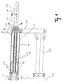
- Fig. 1 only explains the basic structure of the intestinal holding device according to the invention, whereupon then based on Fig. 2 and 3 a preferred embodiment for the construction in the field of gut brake is described.
- the intestine holding device is arranged on a linking gear 43 of a filling machine, not shown, can be filled with the sausage meat in natural or artificial casings to form sausage strands.
- a filling tube 11 Via a rotary drive in the form of a drive shaft 19 of the twist-off gear 43, a filling tube 11 can be rotated.
- the filling tube 11 has at its rear end to a hopper 37, via which it is fed with sausage meat.
- a discharge opening 16 having the end of the filling pipe 11 is mounted in a casing brake 49, in which a funnel 20 is formed.
- the discharge opening 16 can be formed by a pushed onto the filling tube 11, elastic pipe section which rests like a sealing lip on the surface of the hopper 20 and forms an annular gap with the surface of the funnel 20 for the intestine.
- the support member 47 has at its cantilevered end an annular receptacle 22 in which the casing brake 49 is rotatably mounted.
- the filling tube 11 is surrounded by an elongated tubular driving member 15.
- the driving member 15 is pushed onto a tubular drive portion 17 with its rear end, with which it is in frictional engagement via two O-rings 33. While the length of the drive portion 17 is less than one third of the length of the filling tube 11, the tubular driving member 15 is only slightly shorter than the filling tube 11, which extends in the illustrated assembled state with its discharge opening 16 into the hopper 20 inside.
- the tubular drive portion 17 is in turn bolted to the free end of the drive shaft 19.
- the drive portion 17 acts with a radially inwardly projecting clamping flange with the filling tube 11 in the manner of a union nut together such that the filling tube 11 is clamped over its funnel-shaped filling area 37 between the clamping flange and the end face of the drive shaft 19.
- the drive portion 17 of the driving member 15 thus serves as a fastening means for the filling tube eleventh
- the made of a transparent plastic material and a closed, i. fürbrechungspat lateral surface having tubular driving member 15 is plugged in the manner described above with the interposition of the O-rings 33 on the drive section 17 to ensure a safe entrainment of the driving member 15 with rotating drive section 17.
- sausage meat is pressed into the filling tube 11 via the filling funnel 37 when the filling tube 11 is stationary.
- the sausage meat emerging from the dispensing opening 16 of the filling tube 11 pulls the intestine 13 away from the filling tube 11, whereby a sausage 12 is formed.
- a calibration is performed to close the stuffed sausage 12 and then to start filling the next sausage.
- two already prepared sausages 12 are shown, both of which have already been separated from each other by a Darmabwindung 14 and closed.
- the Brätfiguration is stopped and the drive shaft 19 of the Abstellgetriebes 43 set in rotation, whereby the drive portion 17 and the clamped by this to the drive shaft 19 filling tube 11 are synchronously rotated. Due to the frictional connection of the driving member 15 via the O-rings 33 with the drive portion 17, a synchronous rotation of the driving member 15 is ensured.
- the entrainment member 15 in turn is rotatably coupled to the casing brake 49. As a result, during a rotation of the filling tube 11, the casing brake 49 rotates synchronously in order to form twists. As a result, in turn, a reliable synchronous entrainment of the mounted on the filling tube 11 intestine 13 is ensured. This finally enables reliable production of clearly defined twists 14.
- the multi-part trained intestinal brake 49 is not stored directly in the receptacle 22 of the support member 47; Rather, the casing brake 49 is in turn mounted on a ball bearing ring 29 in a multi-part bearing body 31, which in turn is screwed into the receptacle 22 of the support member 47.
- the bearing body 31 has an external thread 41, whereas the Receiving 22 a with the external thread 41 corresponding internal thread 42, in which the bearing body 31 is screwed together with the gutter brake 49 mounted by him.
- the casing brake 49 is translationally displaced in the longitudinal direction of the tubular driving member 15, which selectively targeted the annular gap or the tension in the annular gap between the discharge opening 16 of the filling tube 11 and the intestinal brake 49 and thus the tension of the intestine 13 can be set when filling with sausage meat.
- the casing brake 49 is formed in several parts and consists of a receiving sleeve 23, a front hopper component 25 and a rear hopper component 27 together, which are arranged concentrically with each other.
- the receiving sleeve 23 has a stepped tubular shape and is supported directly by the ball bearing ring 29.
- the receiving sleeve 23 in turn receives the front funnel component 25, which is inserted into the receiving sleeve 23 with the interposition of an O-ring 35 and secured therein by frictional engagement.
- the receiving sleeve 23 and the front funnel component 25 can be coupled in a form-locking non-rotatable manner by, for example, engaging a cam formed on the inner circumference of the receiving sleeve 23 in a corresponding recess in the front funnel component 25 (not shown).
- the rear hopper component 27 is in turn releasably connected to the front hopper component 25.
- the rear funnel component 27 has an external thread
- the front funnel component 25 has a corresponding internal thread into which the rear funnel component 27 is screwed.
- the tubular receiving sleeve 23 in a Rear area a circumferential inner longitudinal teeth 54, which is in engagement with a corresponding longitudinal toothing 56 which is formed at a front portion of the driving member 15, so that the casing brake 49 is rotationally rigidly connected via its receiving sleeve 23 with the driving member 15.
- the splines 54, 56 thus provide a coupling between the driving member 15 and the receiving sleeve 23, which prevents relative rotation of the receiving sleeve 23 and the driving member 15, but allows a translational longitudinal displacement of these two parts to each other, so that the casing brake 49 due to the on or Unscrewing of the bearing body 31 in the receptacle 22 of the support member 47 in the longitudinal direction of the driving member 15 can be moved.
- the rear funnel component 27 has a funnel section 50, on the surface of which a plurality of ridges or ribs 52 are formed. Again Fig. 2 A funnel section 51 formed in the front funnel component 25 adjoins the funnel section 50 of the rear funnel component 27 so that the two funnel sections 50, 51 form a continuous funnel 20.
- the rear funnel section 50 which is provided with the ridges or ribs 52, serves with the in Fig. 2 and 3 not shown, wound up on the filling tube 11 intestinal bead cooperate.
- the intestinal brake 49 acts on the intestine at two points spaced apart in the axial direction.
Landscapes
- Engineering & Computer Science (AREA)
- Life Sciences & Earth Sciences (AREA)
- Wood Science & Technology (AREA)
- Zoology (AREA)
- Food Science & Technology (AREA)
- Mechanical Engineering (AREA)
- Processing Of Meat And Fish (AREA)
Applications Claiming Priority (1)
| Application Number | Priority Date | Filing Date | Title |
|---|---|---|---|
| DE200710061119 DE102007061119A1 (de) | 2007-12-19 | 2007-12-19 | Darmhalteeinrichtung |
Publications (2)
| Publication Number | Publication Date |
|---|---|
| EP2071957A1 true EP2071957A1 (fr) | 2009-06-24 |
| EP2071957B1 EP2071957B1 (fr) | 2013-03-27 |
Family
ID=40303508
Family Applications (1)
| Application Number | Title | Priority Date | Filing Date |
|---|---|---|---|
| EP20080021362 Active EP2071957B1 (fr) | 2007-12-19 | 2008-12-09 | Dispositif de retenue de boyaux |
Country Status (3)
| Country | Link |
|---|---|
| EP (1) | EP2071957B1 (fr) |
| DE (1) | DE102007061119A1 (fr) |
| ES (1) | ES2419104T3 (fr) |
Cited By (1)
| Publication number | Priority date | Publication date | Assignee | Title |
|---|---|---|---|---|
| CN112772699A (zh) * | 2019-11-06 | 2021-05-11 | 韦玛格机械制造有限公司 | 用于填充管状的外皮的设备的肠衣保持设备 |
Families Citing this family (1)
| Publication number | Priority date | Publication date | Assignee | Title |
|---|---|---|---|---|
| DE202013010285U1 (de) | 2013-11-13 | 2015-03-06 | Vemag Maschinenbau Gmbh | Vorrichtung zum Füllen schlauchförmiger Hüllen |
Citations (6)
| Publication number | Priority date | Publication date | Assignee | Title |
|---|---|---|---|---|
| DE190568C (fr) | 1906-11-09 | |||
| US1366183A (en) | 1920-06-01 | 1921-01-18 | Charles W Hottmann | Sausage-linking machine |
| GB850270A (en) * | 1958-07-07 | 1960-10-05 | Alexanderwerk Ag | Improvements in or relating to sausage machines |
| DE8806038U1 (de) * | 1988-05-06 | 1988-06-30 | Hoechst Ag, 6230 Frankfurt | Füllvorrichtung für schlauchförmige Verpackungshüllen |
| DE29517333U1 (de) * | 1995-11-02 | 1997-02-27 | Vemag Maschinenbau GmbH, 27283 Verden | Darmhaltevorrichtung |
| EP1260143A1 (fr) | 2001-05-16 | 2002-11-27 | Heinrich Frey Maschinenbau GmbH | Dispositif de retenue de boyaux |
-
2007
- 2007-12-19 DE DE200710061119 patent/DE102007061119A1/de not_active Withdrawn
-
2008
- 2008-12-09 EP EP20080021362 patent/EP2071957B1/fr active Active
- 2008-12-09 ES ES08021362T patent/ES2419104T3/es active Active
Patent Citations (6)
| Publication number | Priority date | Publication date | Assignee | Title |
|---|---|---|---|---|
| DE190568C (fr) | 1906-11-09 | |||
| US1366183A (en) | 1920-06-01 | 1921-01-18 | Charles W Hottmann | Sausage-linking machine |
| GB850270A (en) * | 1958-07-07 | 1960-10-05 | Alexanderwerk Ag | Improvements in or relating to sausage machines |
| DE8806038U1 (de) * | 1988-05-06 | 1988-06-30 | Hoechst Ag, 6230 Frankfurt | Füllvorrichtung für schlauchförmige Verpackungshüllen |
| DE29517333U1 (de) * | 1995-11-02 | 1997-02-27 | Vemag Maschinenbau GmbH, 27283 Verden | Darmhaltevorrichtung |
| EP1260143A1 (fr) | 2001-05-16 | 2002-11-27 | Heinrich Frey Maschinenbau GmbH | Dispositif de retenue de boyaux |
Cited By (2)
| Publication number | Priority date | Publication date | Assignee | Title |
|---|---|---|---|---|
| CN112772699A (zh) * | 2019-11-06 | 2021-05-11 | 韦玛格机械制造有限公司 | 用于填充管状的外皮的设备的肠衣保持设备 |
| CN112772699B (zh) * | 2019-11-06 | 2023-12-12 | 韦玛格机械制造有限公司 | 用于填充管状的外皮的设备的肠衣保持设备 |
Also Published As
| Publication number | Publication date |
|---|---|
| EP2071957B1 (fr) | 2013-03-27 |
| DE102007061119A1 (de) | 2009-06-25 |
| ES2419104T3 (es) | 2013-08-19 |
Similar Documents
| Publication | Publication Date | Title |
|---|---|---|
| EP1371293B1 (fr) | Appareil et procédé pour la fabrication d'un brin de materiau plastique et tête d'extrusion pour un tel appareil et une telle procédé | |
| DE2614184C2 (de) | Stopfrohranordnung zum Füllen von Wursthüllen | |
| EP0910954B1 (fr) | Procédé et machine de bourrage de la chair à saucisses | |
| DE2025620A1 (de) | Wurstfullvomchtung | |
| EP2071957B1 (fr) | Dispositif de retenue de boyaux | |
| EP1777161B1 (fr) | Machine pour emballer un produit fluide ou granuleux | |
| DE3212164C2 (de) | Darmbremsvorrichtung für eine Wurstfüllmaschine | |
| EP1695627B1 (fr) | Procédé et dispositif de bourrage de boyaux de saucisses | |
| EP0586899B1 (fr) | Dispositif de retenue de boyaux | |
| EP1260143B1 (fr) | Dispositif de retenue de boyaux | |
| DE10052408B4 (de) | Verfahren und Vorrichtung zur Zuführung Flavour zum Tabak eines Rauchartikels | |
| DE29819328U1 (de) | Vorrichtung zum portionierenden Abfüllen von pastösen Produkten | |
| EP2898777B1 (fr) | Freins pour boyaux de saucisses | |
| DE102008061327A1 (de) | Extruderanordnung | |
| DE3519021A1 (de) | Maschine zum abfuellen teigiger medien in eine schlauchfoermige huelle | |
| DE202006010597U1 (de) | Füllvorrichtung und Maschine zum Füllen von Hüllen, insbesondere Wurstdärmen | |
| DE1632143C3 (de) | Tüllenkopf für Wurstfüllmaschinen mit mehreren Tüllen | |
| DE2519705C2 (de) | Vorrichtung zum Strangpressen von Rohren | |
| CH682440A5 (de) | Darmbremsvorrichtung an einer Wurstfüllmaschine. | |
| EP0193062A1 (fr) | Mandrin tournant pour machine à bourrer des saucisses pour la fabrication de saucisses en chapelets | |
| DE1187150B (de) | Vorrichtung zum zeitweiligen Abbremsen und dichten Anlegen einer zu stopfenden Wursthuelle auf der Abdrehtuelle einer Abteil- und Abdrehmaschine | |
| DE3028831A1 (de) | Vorrichtung zum fuellen von wursthuellen | |
| DE2309720A1 (de) | Verfahren und vorrichtung zum raffen von schlauchhuellen | |
| EP1297747B1 (fr) | Dispositif à bourrer des enveloppes tubulaires | |
| DE1927092U (de) | Vorrichtung zum fuellen von schlaeuchen, insbesondere von kunststoffdaermen mit wurstmasse. |
Legal Events
| Date | Code | Title | Description |
|---|---|---|---|
| PUAI | Public reference made under article 153(3) epc to a published international application that has entered the european phase |
Free format text: ORIGINAL CODE: 0009012 |
|
| AK | Designated contracting states |
Kind code of ref document: A1 Designated state(s): AT BE BG CH CY CZ DE DK EE ES FI FR GB GR HR HU IE IS IT LI LT LU LV MC MT NL NO PL PT RO SE SI SK TR |
|
| AX | Request for extension of the european patent |
Extension state: AL BA MK RS |
|
| 17P | Request for examination filed |
Effective date: 20091218 |
|
| 17Q | First examination report despatched |
Effective date: 20100115 |
|
| AKX | Designation fees paid |
Designated state(s): AT BE BG CH CY CZ DE DK EE ES FI FR GB GR HR HU IE IS IT LI LT LU LV MC MT NL NO PL PT RO SE SI SK TR |
|
| GRAP | Despatch of communication of intention to grant a patent |
Free format text: ORIGINAL CODE: EPIDOSNIGR1 |
|
| GRAC | Information related to communication of intention to grant a patent modified |
Free format text: ORIGINAL CODE: EPIDOSCIGR1 |
|
| GRAS | Grant fee paid |
Free format text: ORIGINAL CODE: EPIDOSNIGR3 |
|
| GRAA | (expected) grant |
Free format text: ORIGINAL CODE: 0009210 |
|
| AK | Designated contracting states |
Kind code of ref document: B1 Designated state(s): AT BE BG CH CY CZ DE DK EE ES FI FR GB GR HR HU IE IS IT LI LT LU LV MC MT NL NO PL PT RO SE SI SK TR |
|
| REG | Reference to a national code |
Ref country code: GB Ref legal event code: FG4D Free format text: NOT ENGLISH |
|
| REG | Reference to a national code |
Ref country code: CH Ref legal event code: EP |
|
| REG | Reference to a national code |
Ref country code: AT Ref legal event code: REF Ref document number: 602785 Country of ref document: AT Kind code of ref document: T Effective date: 20130415 |
|
| REG | Reference to a national code |
Ref country code: IE Ref legal event code: FG4D Free format text: LANGUAGE OF EP DOCUMENT: GERMAN |
|
| REG | Reference to a national code |
Ref country code: DE Ref legal event code: R096 Ref document number: 502008009574 Country of ref document: DE Effective date: 20130523 |
|
| PG25 | Lapsed in a contracting state [announced via postgrant information from national office to epo] |
Ref country code: SE Free format text: LAPSE BECAUSE OF FAILURE TO SUBMIT A TRANSLATION OF THE DESCRIPTION OR TO PAY THE FEE WITHIN THE PRESCRIBED TIME-LIMIT Effective date: 20130327 Ref country code: LT Free format text: LAPSE BECAUSE OF FAILURE TO SUBMIT A TRANSLATION OF THE DESCRIPTION OR TO PAY THE FEE WITHIN THE PRESCRIBED TIME-LIMIT Effective date: 20130327 Ref country code: NO Free format text: LAPSE BECAUSE OF FAILURE TO SUBMIT A TRANSLATION OF THE DESCRIPTION OR TO PAY THE FEE WITHIN THE PRESCRIBED TIME-LIMIT Effective date: 20130627 Ref country code: BG Free format text: LAPSE BECAUSE OF FAILURE TO SUBMIT A TRANSLATION OF THE DESCRIPTION OR TO PAY THE FEE WITHIN THE PRESCRIBED TIME-LIMIT Effective date: 20130627 |
|
| REG | Reference to a national code |
Ref country code: NL Ref legal event code: T3 |
|
| REG | Reference to a national code |
Ref country code: ES Ref legal event code: FG2A Ref document number: 2419104 Country of ref document: ES Kind code of ref document: T3 Effective date: 20130819 |
|
| REG | Reference to a national code |
Ref country code: LT Ref legal event code: MG4D |
|
| PG25 | Lapsed in a contracting state [announced via postgrant information from national office to epo] |
Ref country code: LV Free format text: LAPSE BECAUSE OF FAILURE TO SUBMIT A TRANSLATION OF THE DESCRIPTION OR TO PAY THE FEE WITHIN THE PRESCRIBED TIME-LIMIT Effective date: 20130327 Ref country code: GR Free format text: LAPSE BECAUSE OF FAILURE TO SUBMIT A TRANSLATION OF THE DESCRIPTION OR TO PAY THE FEE WITHIN THE PRESCRIBED TIME-LIMIT Effective date: 20130628 Ref country code: FI Free format text: LAPSE BECAUSE OF FAILURE TO SUBMIT A TRANSLATION OF THE DESCRIPTION OR TO PAY THE FEE WITHIN THE PRESCRIBED TIME-LIMIT Effective date: 20130327 Ref country code: SI Free format text: LAPSE BECAUSE OF FAILURE TO SUBMIT A TRANSLATION OF THE DESCRIPTION OR TO PAY THE FEE WITHIN THE PRESCRIBED TIME-LIMIT Effective date: 20130327 |
|
| PG25 | Lapsed in a contracting state [announced via postgrant information from national office to epo] |
Ref country code: HR Free format text: LAPSE BECAUSE OF FAILURE TO SUBMIT A TRANSLATION OF THE DESCRIPTION OR TO PAY THE FEE WITHIN THE PRESCRIBED TIME-LIMIT Effective date: 20130327 |
|
| PG25 | Lapsed in a contracting state [announced via postgrant information from national office to epo] |
Ref country code: RO Free format text: LAPSE BECAUSE OF FAILURE TO SUBMIT A TRANSLATION OF THE DESCRIPTION OR TO PAY THE FEE WITHIN THE PRESCRIBED TIME-LIMIT Effective date: 20130327 Ref country code: SK Free format text: LAPSE BECAUSE OF FAILURE TO SUBMIT A TRANSLATION OF THE DESCRIPTION OR TO PAY THE FEE WITHIN THE PRESCRIBED TIME-LIMIT Effective date: 20130327 Ref country code: EE Free format text: LAPSE BECAUSE OF FAILURE TO SUBMIT A TRANSLATION OF THE DESCRIPTION OR TO PAY THE FEE WITHIN THE PRESCRIBED TIME-LIMIT Effective date: 20130327 Ref country code: IS Free format text: LAPSE BECAUSE OF FAILURE TO SUBMIT A TRANSLATION OF THE DESCRIPTION OR TO PAY THE FEE WITHIN THE PRESCRIBED TIME-LIMIT Effective date: 20130727 Ref country code: CZ Free format text: LAPSE BECAUSE OF FAILURE TO SUBMIT A TRANSLATION OF THE DESCRIPTION OR TO PAY THE FEE WITHIN THE PRESCRIBED TIME-LIMIT Effective date: 20130327 Ref country code: PT Free format text: LAPSE BECAUSE OF FAILURE TO SUBMIT A TRANSLATION OF THE DESCRIPTION OR TO PAY THE FEE WITHIN THE PRESCRIBED TIME-LIMIT Effective date: 20130729 |
|
| PG25 | Lapsed in a contracting state [announced via postgrant information from national office to epo] |
Ref country code: CY Free format text: LAPSE BECAUSE OF FAILURE TO SUBMIT A TRANSLATION OF THE DESCRIPTION OR TO PAY THE FEE WITHIN THE PRESCRIBED TIME-LIMIT Effective date: 20130327 Ref country code: PL Free format text: LAPSE BECAUSE OF FAILURE TO SUBMIT A TRANSLATION OF THE DESCRIPTION OR TO PAY THE FEE WITHIN THE PRESCRIBED TIME-LIMIT Effective date: 20130327 |
|
| PG25 | Lapsed in a contracting state [announced via postgrant information from national office to epo] |
Ref country code: DK Free format text: LAPSE BECAUSE OF FAILURE TO SUBMIT A TRANSLATION OF THE DESCRIPTION OR TO PAY THE FEE WITHIN THE PRESCRIBED TIME-LIMIT Effective date: 20130327 |
|
| PLBE | No opposition filed within time limit |
Free format text: ORIGINAL CODE: 0009261 |
|
| STAA | Information on the status of an ep patent application or granted ep patent |
Free format text: STATUS: NO OPPOSITION FILED WITHIN TIME LIMIT |
|
| 26N | No opposition filed |
Effective date: 20140103 |
|
| REG | Reference to a national code |
Ref country code: DE Ref legal event code: R097 Ref document number: 502008009574 Country of ref document: DE Effective date: 20140103 |
|
| REG | Reference to a national code |
Ref country code: CH Ref legal event code: PL |
|
| GBPC | Gb: european patent ceased through non-payment of renewal fee |
Effective date: 20131209 |
|
| PG25 | Lapsed in a contracting state [announced via postgrant information from national office to epo] |
Ref country code: MC Free format text: LAPSE BECAUSE OF FAILURE TO SUBMIT A TRANSLATION OF THE DESCRIPTION OR TO PAY THE FEE WITHIN THE PRESCRIBED TIME-LIMIT Effective date: 20130327 Ref country code: LU Free format text: LAPSE BECAUSE OF FAILURE TO SUBMIT A TRANSLATION OF THE DESCRIPTION OR TO PAY THE FEE WITHIN THE PRESCRIBED TIME-LIMIT Effective date: 20131209 |
|
| REG | Reference to a national code |
Ref country code: IE Ref legal event code: MM4A |
|
| REG | Reference to a national code |
Ref country code: FR Ref legal event code: ST Effective date: 20140829 |
|
| PG25 | Lapsed in a contracting state [announced via postgrant information from national office to epo] |
Ref country code: LI Free format text: LAPSE BECAUSE OF NON-PAYMENT OF DUE FEES Effective date: 20131231 Ref country code: IE Free format text: LAPSE BECAUSE OF NON-PAYMENT OF DUE FEES Effective date: 20131209 Ref country code: CH Free format text: LAPSE BECAUSE OF NON-PAYMENT OF DUE FEES Effective date: 20131231 |
|
| PG25 | Lapsed in a contracting state [announced via postgrant information from national office to epo] |
Ref country code: GB Free format text: LAPSE BECAUSE OF NON-PAYMENT OF DUE FEES Effective date: 20131209 Ref country code: FR Free format text: LAPSE BECAUSE OF NON-PAYMENT OF DUE FEES Effective date: 20131231 |
|
| PG25 | Lapsed in a contracting state [announced via postgrant information from national office to epo] |
Ref country code: TR Free format text: LAPSE BECAUSE OF FAILURE TO SUBMIT A TRANSLATION OF THE DESCRIPTION OR TO PAY THE FEE WITHIN THE PRESCRIBED TIME-LIMIT Effective date: 20130327 |
|
| PG25 | Lapsed in a contracting state [announced via postgrant information from national office to epo] |
Ref country code: HU Free format text: LAPSE BECAUSE OF FAILURE TO SUBMIT A TRANSLATION OF THE DESCRIPTION OR TO PAY THE FEE WITHIN THE PRESCRIBED TIME-LIMIT; INVALID AB INITIO Effective date: 20081209 |
|
| PG25 | Lapsed in a contracting state [announced via postgrant information from national office to epo] |
Ref country code: MT Free format text: LAPSE BECAUSE OF FAILURE TO SUBMIT A TRANSLATION OF THE DESCRIPTION OR TO PAY THE FEE WITHIN THE PRESCRIBED TIME-LIMIT Effective date: 20130327 |
|
| PGFP | Annual fee paid to national office [announced via postgrant information from national office to epo] |
Ref country code: NL Payment date: 20211221 Year of fee payment: 14 |
|
| REG | Reference to a national code |
Ref country code: NL Ref legal event code: MM Effective date: 20230101 |
|
| PG25 | Lapsed in a contracting state [announced via postgrant information from national office to epo] |
Ref country code: NL Free format text: LAPSE BECAUSE OF NON-PAYMENT OF DUE FEES Effective date: 20230101 |
|
| PGFP | Annual fee paid to national office [announced via postgrant information from national office to epo] |
Ref country code: DE Payment date: 20250226 Year of fee payment: 17 |
|
| PGFP | Annual fee paid to national office [announced via postgrant information from national office to epo] |
Ref country code: ES Payment date: 20250131 Year of fee payment: 17 |
|
| PGFP | Annual fee paid to national office [announced via postgrant information from national office to epo] |
Ref country code: AT Payment date: 20251222 Year of fee payment: 18 |
|
| PGFP | Annual fee paid to national office [announced via postgrant information from national office to epo] |
Ref country code: IT Payment date: 20251223 Year of fee payment: 18 |
|
| PGFP | Annual fee paid to national office [announced via postgrant information from national office to epo] |
Ref country code: BE Payment date: 20251219 Year of fee payment: 18 |