EP2071982B1 - Dispositif d'articulation conçu pour un coude de bras de store - Google Patents
Dispositif d'articulation conçu pour un coude de bras de store Download PDFInfo
- Publication number
- EP2071982B1 EP2071982B1 EP06819994.2A EP06819994A EP2071982B1 EP 2071982 B1 EP2071982 B1 EP 2071982B1 EP 06819994 A EP06819994 A EP 06819994A EP 2071982 B1 EP2071982 B1 EP 2071982B1
- Authority
- EP
- European Patent Office
- Prior art keywords
- core
- bearing
- arm elbow
- annular element
- axis
- Prior art date
- Legal status (The legal status is an assumption and is not a legal conclusion. Google has not performed a legal analysis and makes no representation as to the accuracy of the status listed.)
- Active
Links
Images


Classifications
-
- E—FIXED CONSTRUCTIONS
- E04—BUILDING
- E04F—FINISHING WORK ON BUILDINGS, e.g. STAIRS, FLOORS
- E04F10/00—Sunshades, e.g. Florentine blinds or jalousies; Outside screens; Awnings or baldachins
- E04F10/02—Sunshades, e.g. Florentine blinds or jalousies; Outside screens; Awnings or baldachins of flexible canopy materials, e.g. canvas ; Baldachins
- E04F10/06—Sunshades, e.g. Florentine blinds or jalousies; Outside screens; Awnings or baldachins of flexible canopy materials, e.g. canvas ; Baldachins comprising a roller-blind with means for holding the end away from a building
- E04F10/0611—Sunshades, e.g. Florentine blinds or jalousies; Outside screens; Awnings or baldachins of flexible canopy materials, e.g. canvas ; Baldachins comprising a roller-blind with means for holding the end away from a building with articulated arms supporting the movable end of the blind for deployment of the blind
- E04F10/0618—Sunshades, e.g. Florentine blinds or jalousies; Outside screens; Awnings or baldachins of flexible canopy materials, e.g. canvas ; Baldachins comprising a roller-blind with means for holding the end away from a building with articulated arms supporting the movable end of the blind for deployment of the blind whereby the pivot axis of the articulation is perpendicular to the roller
- E04F10/0622—Sunshades, e.g. Florentine blinds or jalousies; Outside screens; Awnings or baldachins of flexible canopy materials, e.g. canvas ; Baldachins comprising a roller-blind with means for holding the end away from a building with articulated arms supporting the movable end of the blind for deployment of the blind whereby the pivot axis of the articulation is perpendicular to the roller whereby the plane defined by three consecutive articulation points of an articulated arm is not parallel to the rotation axis of the roller, e.g. to create a saddle type roof construction or to prevent contact between the cloth and the arm sections
Definitions
- the present invention relates to an articulated awning arm elbow formed by a forearm and an arm in said elbow, where the free end of the forearm is provided with a configuration for articulated attachment to a load bar fixed to a front edge of the awning canvas and the free end of the arm is provided with a configuration for articulated attachment to a fixed support adjacent to a winding tube for the canvas, and where inside the arm there is arranged at least one elastic traction member connected to flexible tie rod element having an end anchored in the mentioned articulated awning arm elbow.
- the articulation device To guide a relative rotation between the forearm and arm elbow parts around said axis, and to support the forearm on the arm in a cantilevered manner, the articulation device includes bearing means formed by a pair of annular parts, made of a plastic material, assembled on the surrounding wall of the arm elbow part. These annular parts define a pair of first conical surfaces which in an operative situation face one another and are in contact with a corresponding pair of second conical surfaces formed in the core and in a centring part, respectively, which are integral with the forearm elbow part. The first and second conical surfaces are conjugated and provided for a relative sliding.
- a tubular shank coaxial with the axis is inserted in a hollow interior of the core.
- One of the branches of the fork of the forearm elbow part defines a hole for an end of said shank and the other branch of the fork defines an opening into which the mentioned centring part is fitted, which centring part in turn has a hole for the other end of the shank.
- the centring part is configured to block the rotation of the core.
- the forearm and arm elbow parts, as well as the core and the centring part are generally obtained by the injection moulding of a lightweight metal alloy, such as aluminium, and the correct adjustment of the conical surfaces demands strict manufacture and assembly tolerances that are difficult to achieve by means of such moulded aluminium parts without a subsequent machining.
- the lack of a correct adjustment can give rise to squeaks while bending and straightening the elbow.
- a play, however small it is, in the articulation of the elbow can cause a misalignment of the correct position of the forearm with respect to the arm, and this can create interferences, for example, when the articulated arm must be automatically introduced in a bent position into a box during an operation for drawing in the awning. This misalignment will be greater the longer the forearm is. Therefore, a lack of adjustment in the articulation of the elbow limits the maximum length that the forearm can have to be supported in a cantilevered manner by the bearing means in a suitable position.
- the friction forces existing in the articulation device for the elbow are to the detriment of the force exerted by the elastic traction member, and as a result there is a decrease in the tension of the canvas.
- the present invention contributes to overcoming the previous and other drawbacks by providing an articulated awning arm elbow formed by a forearm and an arm in said elbow comprising:
- the articulated awning arm elbow includes two bearing units, at least one of which is a roll bearing in which said first annular element fixed to the forearm elbow part defines an inner roll track and said second annular element fixed to the arm elbow part defines an outer roll track.
- the roll bearing can be of different types, including ball bearings, needle bearings, cylindrical or tapered roller bearings, etc.
- a suitable type of roll bearing is, for example, a single-row rigid ball bearing, preferably of stainless steel and sealed or provided with side protections. The single-row rigid ball bearing withstands both radial and axial forces and is commercially available.
- the parts forming the structure of the articulated awning arm elbow i.e., the forearm and arm elbow parts, as well as the core and centring parts, are generally obtained by the injection moulding of a lightweight metal alloy, such as, for example, an aluminium alloy, and are usually completely coated with a layer of paint or lacquer.
- a lightweight metal alloy such as, for example, an aluminium alloy
- the core and in the surrounding wall defined by the arm elbow part there are seats for the first annular element and the second annular element, respectively, of the roll bearing. These seats are formed during the moulding operation and coated with the layer of paint or lacquer. Due to the demands of the moulding technique, specifically to facilitate the demolding, the surfaces oriented in the demolding direction must be slightly conical. For this reason, in other applications, the seats for roll bearings and other components generally require being machined after the moulding to eliminate or rectify the mentioned conicity, which makes the manufacturing process considerably more expensive.
- the seats for the roll bearings are configured such that the roll bearings can be directly housed in the housings as they are obtained in the parts shaped by injection moulding, even having been subsequently lacquered or painted, without needing a prior machining.
- each of the seats in the articulated awning arm elbow of the present invention comprises a conical surface, coaxial with the axis of the articulation and provided with a degree of conicity, from which there project ribs defining radial support surfaces, each of which has at least one edge coinciding with a cone coaxial with the axis of the articulation and also provided with a degree of conicity.
- the degrees of conicity of the conical surface and of the radial support surfaces of the ribs are small and no more than those necessary to allow a correct demolding of the core and/or of the arm elbow part after the operation for obtaining them by injection moulding.
- the radial support surfaces of the ribs are adapted to receive by pressurized insertion a cylindrical radial support surface of the roll bearing.
- the mentioned ribs are sized for the purpose of at least one part of their radial support surfaces being adjusted with interference with the radial rest surface of the roll bearing, taking into account the thickness of the layer of paint or lacquer when there is one.
- the roll bearing sweeps an amount of material of the ribs during an operation for installing the roll bearing by pressurized insertion in the axial direction in the seat until an axial rest surface of the roll bearing makes contact with an axial support surface of the seat perpendicular to the axis of the articulation.
- a circumferential channel adapted to receive and house the possible material of the ribs of the seat pulled off by the roll bearing, whether it is aluminium alloy or paint or lacquer, or a combination of both, during the operation for installing the roll bearing by pressurized insertion.
- the articulated awning arm elbow includes two bearing units, at least one of which is a friction bearing in which the mentioned facing surfaces comprise respective first and second cylindrical surface portions in contact, to withstand forces in the radial direction, and respective first and second annulus surface portions in contact, to withstand forces in the axial direction.
- the first and second annular elements are preferably made of different materials with a low coefficient of friction between one another. Steel and bronze, steel and plastic, bronze and plastic, for example, among others, can be mentioned as suitable pairs of materials for the first and second annular elements of the friction bearing.
- the corresponding structural part of the articulated awning arm elbow defines a seat similar to that described above in relation to the bearing, for receiving the annular element of the friction bearing by pressurized insertion.
- the seat for the annular element of the friction bearing comprises a conical radial support surface, coaxial with the axis of the articulation, provided with a small degree of conicity suitable for facilitating the demolding of the part during its manufacture by injection moulding.
- This conical radial support surface is adapted to receive by pressurized insertion radial rest surfaces formed in ribs projecting from a surface of the friction bearing.
- Each of these radial rest surfaces of the ribs has at least one edge preferably coinciding with a cylinder.
- the housing also includes an axial support surface perpendicular to the axis, adapted to receive an axial rest surface of the friction bearing.
- a circumferential channel adjacent to said conical surface is formed on this axial support surface to receive and house the possible material pulled off by the annular element of the friction bearing from the conical surface of the seat during the operation for installing the annular element by pressurized insertion in the axial direction.
- the seat is preferably machined to provide a cylindrical radial rest surface ensuring a complete backing for a cylindrical radial rest surface of the annular element.
- a feature common to the embodiment with a roll bearing and to the embodiment with a friction bearing is that a structural part of the articulated awning arm elbow includes a seat for at least one of the two annular elements of the roll bearing or friction bearing, where the mentioned seat has one or more surfaces coinciding with a cone coaxial with the axis of the articulation provided with a degree of conicity suitable for facilitating demolding, and adapted to receive by pressurized insertion one or more surfaces coinciding with a cylinder coaxial with the axis of the articulation, formed in the corresponding annular element of the roll bearing or friction bearing.
- the present invention contemplates the possibility of the articulated awning arm elbow including a single bearing unit, either in the form of a roll bearing or of a friction bearing, provided that the single roll bearing or friction bearing is of a suitable type and is properly sized.
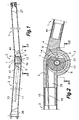
- the articulated awning arm elbow of the present invention is formed by a forearm 1 and an arm 2 in an elbow 3 for one to rotate with respect to the other around an axis 7.
- the forearm 1 is formed by an elongated tubular section finished at a first end by a forearm elbow part 4 adapted for the articulated attachment of the forearm 1 to the arm 2 and at an opposite second end by a connecting part 27 adapted for the articulated attachment of the free end of the forearm 1 to a load bar (not shown) fixed to a front edge of a canvas of the awning.
- the arm 2 is formed by an elongated tubular section finished at a first end by an arm elbow part 5 adapted for the articulated attachment of the arm 2 to the forearm 1 and at an opposite second end by a connecting part 28 adapted for the articulated attachment of the free end of the arm 2 to a support (not shown) adjacent to a winding tube for the canvas of the awning.
- Bearing means are arranged to guide a relative rotation between the forearm elbow part 4 and the arm elbow part 5 around the axis 7, and to support the forearm 1 on the arm 2 in a cantilevered manner.
- the forearm and arm elbow parts 1, 2 include plug-in configurations 44, 45 adapted to be inserted in the open ends of the tubular sections of the forearm 1 and the arm 2, respectively.
- the mentioned plug-in configurations 44, 45 can be delimited by inclined flanges 46, 47 adapted to abut against inclined cut ends of the tubular sections of the forearm 1 and the arm 2, respectively, according to international patent application WO 2005/017279 .
- the connecting parts 27 and 28 can be coupled to the respective tubular sections of the forearm 1 and the arm 2 by means of plug-in configurations provided with inclined flanges similar to those mentioned.
- the forearm elbow part 4 defines a fork between the branches 4a, 4b of which a core 6 configured around the axis 7 is fixedly supported.
- an anchoring configuration 8 ( Figure 2 ) adapted to couple an enlarged end 9 of a flexible tie rod element 10 connected to an elastic member 11 in the form of a helical traction spring secured in an anchor 12 inside said arm 2.
- an elastic member 11 in the form of a helical traction spring secured in an anchor 12 inside said arm 2.
- the arm elbow part 5 defines a surrounding wall 13 arranged around said core 6, there being a clearance 14 between the surrounding wall 13 and the core 6 to accommodate said flexible tie rod element 10.
- the surrounding wall 13 has an opening communicating the clearance 14 with a passage 29 formed through the arm elbow part 5 and the corresponding plug-in configuration to allow the passage of the flexible tie rod element 10 into the tubular section of the arm 2.
- Documents ES-A-2159211 and ES-A-2191843 disclose a flexible tie rod element such as the one described above, and international patent application WO 2005/001728 describes an alternative arrangement for the function of the elastic traction member of the flexible tie rod element compatible with the articulated awning arm elbow of the present invention.
- the tubular sections of the forearm 1 and the arm 2 can be extruded profiles made of a lightweight metal alloy, for example, an aluminium alloy, and the structural parts of the articulated awning arm elbow, i.e., the forearm and arm elbow parts 4, 5, the core 6 and centring parts 23 are designed to be obtained by injection moulding of a lightweight metal alloy, for example, an aluminium alloy.
- a lightweight metal alloy for example, an aluminium alloy
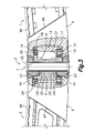
- the mentioned bearing means of the articulated awning arm elbow include a pair of bearing units located adjacent to the branches 4a, 4b of the fork, or in other words, at opposite ends of the core 6.
- the bearing unit located at the lower end of the core 6 is a roll bearing 15 and the bearing unit located at the upper end of the core 6 is a friction bearing 19. This is so because the lower end of the articulation has more mechanical stress than the upper end, although there is no limitation for the construction being the reverse one.
- the mentioned roll bearing 15 is of a conventional type and comprises a first annular element 16 which is fixed to the forearm elbow part 4 and a second annular element 17 which is fixed to the arm elbow part 5.
- These first and second annular elements 16, 17 include respective facing surfaces defining inner and outer roll tracks, respectively, on which a plurality of rolling elements 18 arranged therebetween roll.
- the facing surfaces of the first and second annular elements 16, 17 are thus adapted to mutually cooperate in the functions of the bearing means.
- the rolling elements 18 can be balls, cylindrical rollers, tapered rollers, needles, etc.
- the roll bearing 15 is a conventional single-row rigid ball bearing, which is adapted to withstand radial forces and axial forces.
- the roll bearing 15 is preferably made of stainless steel and sealed to be weather-resistant.
- the first annular element 16 of the roll bearing 15 is assembled on the core 6, which is in turn fixed to the forearm elbow part 4 by means of centring parts 23 and a central shank 22, as will be explained in detail below, and the second annular element 17 is assembled on the surrounding wall 13 forming part of the arm elbow part 5.
- the core 6 defines a seat for the first annular element 16 of the roll bearing 15 and the surrounding wall 13 defines a seat for the second annular element 17 of the roll bearing 15.
- each of the mentioned seats comprises a conical surface 30, coaxial with the axis 7, provided with a small degree of conicity, and ribs 31 projecting from said conical surface 30.
- the mentioned ribs 31 are distributed around the axis 7 and each of them defines a radial support surface having at least one edge coinciding with an imaginary cone coaxial with the axis 7 and likewise provided with a small degree of conicity.
- the entire radial support surface of each rib 31 coincides with said imaginary cone.
- the mentioned radial support surfaces of the ribs 31 are adapted to receive by pressurized insertion in the axial direction cylindrical inner and outer radial rest surfaces existing in the corresponding first and second annular elements 16, 17 of the roll bearing 15.
- the bottoms of the seats are formed by axial support surfaces 32, perpendicular to the axis 7, adapted to receive axial rest surfaces existing in the corresponding first and second annular elements 16, 17 of the roll bearing 15.
- axial support surfaces 32 In each of said axial support surfaces 32 there is formed a circumferential channel 33 located adjacent to the ribs 31.
- the degree of conicity of the conical surface 30 and the degree of conicity of the radial support surfaces of the ribs 31 is relatively small, for example, less than one degree, and is sufficient to allow the demolding when the core 6 and/or the arm elbow part 5 defining the surrounding wall 13 are obtained by the injection moulding of a lightweight metal alloy, for example, an aluminium alloy.
- a lightweight metal alloy for example, an aluminium alloy.
- the core 6 and/or the arm elbow part 5 defining the surrounding wall 13 can be completely coated with a layer of paint or lacquer applied after its shaping by injection moulding.
- the first and second annular elements 16, 17 of the roll bearing 15 interfere with the support surfaces of the ribs 31 pulling off some of the material and/or coating thereof, until the axial rest surfaces of the roll bearing 15 make contact with the axial support surfaces 32 of the seats.
- the material or coating of the seats pulled off by the roll bearing 15 is received and retained in the corresponding channels 33 in order to not interfere in the contact between the corresponding axial rest surfaces of the roll bearing 15 and the axial support surfaces 32 of the seats.
- the roll bearing 15 is thus perfectly seated in the seats.
- the friction bearing 19 comprises a first annular element 20 assembled on the core 6, which is in turn fixed to the forearm elbow part 4, and a second annular element 21 fixed to the surrounding wall 13, which forms part of the arm elbow part 5.
- the first and second annular elements 20, 21 of the friction bearing 19 include respective facing surfaces adapted to mutually cooperate in the functions of the bearing means. These facing surfaces comprises respective first and second cylindrical surface portions in contact, arranged to withstand radial forces, and respective first and second annulus surface portions in contact, arranged to withstand axial forces.
- the first annular element 20 has the first cylindrical portion formed in a cylindrical bushing and the first annulus portion formed in a perimetric flange 26 projecting from said cylindrical bushing.
- the second annular element 21 has the second cylindrical portion and the second annulus portion formed in side and front surfaces, respectively, of a cylindrical bushing.
- the core 6 and the surrounding wall 13 define seats for the first annular element 20 and the second annular element 21, respectively.
- the first annular element 20 is made of steel, preferably stainless steel
- the second annular element 21 is made of bronze.
- the seat formed in the core 6 for the steel first annular element 20 of the friction bearing 19 is similar to the seats described above for the roll bearing 15, and comprises a conical surface 34 coaxial with the axis 7, provided with a degree of conicity, ribs 35 projecting from said conical surface 34 defining radial support surfaces, each of which has at least one edge coinciding with an imaginary cone coaxial with the axis 7 provided with a degree of conicity.
- each rib 35 coincides with said imaginary cone.
- These radial support surfaces of the ribs 35 are adapted to receive by pressurized insertion in the axial direction a cylindrical radial rest surface of the friction bearing 19.
- the seat further comprises an axial support surface 36 perpendicular to the axis 7 adapted to receive an axial rest surface of the friction bearing 19.
- In said axial support surface 36 there is formed a circumferential channel 37 adjacent to said ribs 35, the function of which is similar to that described above in relation to Figure 7 to receive and retain material or coating of the seats pulled off by the first annular element 20 of the friction bearing 19 during an operation for installing by pressurized insertion in the axial direction.
- the mentioned perimetric flange 26 of the first annular element 20 has a decreasing thickness to compensate an inclination of the inner faces of the branches 4a, 4b of the fork necessary for demolding the forearm elbow part 4 while it is obtained by injection moulding.
- the perimetric flange 26 and the corresponding branch 4a of the fork have respective mutually fitting configurations to prevent a relative rotation.
- the seat comprises a conical radial support surface 38, coaxial with the axis 7, provided with a degree of conicity and adapted to receive by pressurized insertion radial rest surfaces formed in ribs 39 projecting from a surface of the friction bearing 19, as best shown in the detail of Figure 10 .
- the mentioned radial rest surfaces of the ribs 39 of the second annular element 21 comprise at least one edge coinciding with an imaginary cylinder coaxial with the axis 7 of the articulation.
- the entire radial rest surface of each rib 39 coincides with said imaginary cylinder.
- the seat further comprises an axial support surface 40 perpendicular to the axis 7 and adapted to receive an axial rest surface of the second annular element 21 of the friction bearing 19.
- a circumferential channel 41 is formed in said axial support surface 40 adjacent to said radial support surface 38 to receive and retain material or coating of the conical surface 38 of the seat pulled of by the second annular element 21 of the friction bearing 19, or house deformed material of the ribs 39 of the second annular element 21 of the friction bearing 19 during an operation for installing by pressurized insertion in the axial direction.
- the structural parts of the articulated awning arm elbow are obtained by the injection moulding of a lightweight metal alloy, for example, an aluminium alloy
- the degree of conicity of the conical surface 34 and of the radial support surfaces of the ribs 35 in the seat for the first annular element 20, as well as the degree of conicity of the radial support surface 38 in the seat for the second annular element 21 are adapted to facilitate the demolding during the process for obtaining the core 6 and the arm elbow part 5 defining the surrounding wall 13 by injection moulding.
- first and second annular elements 20, 21 of the friction bearing 19 could obviously be reversed or be others than steel and bronze, in which cases the constructions of the first and second annular elements 20, 21 and of their seats could be reversed in relation to those described with reference to Figures 9 and 10 .
- Figure 11 shows an alternative embodiment for the bearing unit formed by the friction bearing 19, where the first annular element 20 is made of steel and the second annular element 21 is a relatively flexible or elastic material, based on a plastic polymer.
- the constructions of the first annular element 20 and of its seat in the core 6 are identical to those described above in relation to Figure 9 .
- the seat for the second annular element 21 formed in the surrounding wall 13 defines a cylindrical radial support surface 42, coaxial with the axis 7, adapted to receive by pressurized insertion a radial rest surface of the friction bearing 19, and an axial support surface 43 perpendicular to the axis 7 and adapted to receive an axial rest surface of the friction bearing 19.
- the annulus surface of the second annular element 21 is preferably defined in a perimetric flange 44 projecting from the corresponding cylindrical bushing, and the seat also provides a support surface for said perimetric flange 44.
- At least the mentioned cylindrical radial support surface 42 is obtained by modification of a conical wall by means of a machining operation carried out after obtaining the arm elbow part 5 by injection moulding and eventually after applying a layer of paint or lacquer.
- Figure 4 shows another embodiment in which said bearing means include two of said bearing units, which are both roll bearings 15.
- the first annular elements 16 of both roll bearings 15 are assembled on the core 6, which is in turn fixed to the forearm elbow part 4, and the second annular elements 17 of both roll bearings 15 are assembled on the surrounding wall 13 forming part of the arm elbow part 5.
- the core 6 and in the surrounding wall 13 there are formed corresponding seats similar to those described above in relation to Figures 7 and 8 .
- Figure 5 shows yet another embodiment in which said bearing means include two bearing units formed by a pair of friction bearings 19, where the first annular elements 20 of both friction bearings 19 are assembled on the core 6, which is in turn fixed to the forearm elbow part 4, and the second annular elements 21 of both friction bearings 19 are assembled on the surrounding wall 13 forming part of the arm elbow part 5.
- the core 6 and in the surrounding wall 13 there are formed corresponding seats similar to those described above in relation to Figure 9 , and the second annular elements 21 of the friction bearings 19 are constructed as has been described above in relation to Figures 9 and 10 .
- the core 6 comprises a hole into which a central shank 22 coaxial with the axis 7 is inserted.
- the mentioned hole of the core has a double conicity to facilitate its demolding, whereas the central shank 22 is cylindrical.
- the branches 4a, 4b of the fork defined by the forearm elbow part 4 have formed therein respective openings into which corresponding centring parts 23 are inserted, provided with respective holes in which end portions of said central shank 22 are housed.
- centring parts 23 and the corresponding openings formed in the branches 4a, 4b of the fork have complementary configurations (not shown) adapted to prevent a relative rotation between each centring part 23 and the corresponding branch 4a, 4b of the fork in which it is installed.
- each of said centring parts 23 comprises a projecting configuration 24 adapted to be fitted into a corresponding cavity 25 formed in the core 6, which prevents a relative rotation between the core 6 the centring parts 23.
- the central shank 22 is tubular and has its ends flared against the mouths of the holes of the centring parts 23.
- the ends of the central shank 22 are flared in a final assembly operation, whereby the core 6 and the centring parts 23 are packed together with the fork 4a, 4b defined by the forearm elbow part 4, and the core 6 is integrally fixed to the forearm elbow part 4.
- Plastic decorative covers (not shown) can be coupled on the flared ends of the central shank 22.
- Figure 6 shows an alternative arrangement for the embodiment described above in relation to Figure 3 , where the bearing means include a roll bearing 15 and a friction bearing 19.
- the construction of the friction bearing 19 and of the corresponding seats for the first and second annular elements 20, 21 in the core 6 and the surrounding wall 13 are similar to those described above in relation to Figures 3 , 7 and 8 .
- the first annular element 16 of the roll bearing 15 is assembled on the central shank 22, more specifically, the core 6 leaves a portion of the central shank 22 bare, on which bare portion the roll bearing 15 is assembled.
- the mentioned bare portion of the central shank 22 acts as the radial support surface for the radial rest surface of the first annular element 16 of the roll bearing 15.
- An end of the core 6 and an end of the corresponding centring part 23 provide axial support surfaces 48, 49 for the axial rest surfaces on both sides of the first annular element 16 of the roll bearing 15.
- the seat formed in the surrounding wall 13 for the second annular element 17 of the roll bearing 15 is similar to that described above in relation to Figures 3 , 7 and 8 .
- the construction of the friction bearing 19 as well as of the seats formed in the core 6 and in the surrounding wall 13 for the first and second annular elements 20, 21 of the friction bearing 19 is similar to that described above in relation to Figures 3 , 9 and 10 .
Landscapes
- Engineering & Computer Science (AREA)
- Architecture (AREA)
- Civil Engineering (AREA)
- Structural Engineering (AREA)
- Sliding-Contact Bearings (AREA)
- Pivots And Pivotal Connections (AREA)
Claims (15)
- Coude de bras de store articulé constitué par un avant-bras (1) et un bras (2) dans ledit coude (1), comprenant:une partie de coude d'avant-bras (4) définissant une fourche entre les branches (4a, 4b) dont un noyau (6) configuré autour d'un axe (7) est supporté fixement, avec une configuration d'ancrage (8) qui est formée dans ledit noyau (6) pour coupler une extrémité agrandie (9) d'un élément de tirant flexible (10) connecté à au moins un élément élastique (11) fixé à l'intérieur dudit bras (2);une partie de coude de bras (5) qui définit une paroi périphérique (13) agencée autour dudit noyau (6) avec un espace (14) entre les deux pour recevoir ledit élément de tirant flexible (10);des moyens de palier agencés pour guider une rotation relative entre ladite partie de coude d'avant-bras (4) et ladite partie de coude de bras (5) autour dudit axe (7) et pour supporter l'avant-bras (1) dans le bras (2), lesdits moyens de palier comprenant au moins une unité de palier comprenant un premier élément annulaire (16, 20) qui est fixé à la partie de coude d'avant-bras (4) et un deuxième élément annulaire (17, 21) qui est fixé à la partie de coude de bras (5), lesdits premier et deuxième éléments annulaires (16, 20; 17, 21) présentant des surfaces opposées respectives adaptées pour coopérer mutuellement dans les fonctions des moyens de palier;le noyau (6) fixé à la partie de coude d'avant-bras (4) et la paroi périphérique (13) définie par la partie de coude de bras (5) comprennent des supports respectifs pour ledit premier élément annulaire (16, 20) et ledit deuxième élément annulaire (17, 21), dans lequel au moins l'un desdits supports comprend:une surface conique (30, 34) coaxiale avec l'axe (7),des nervures (31, 35) qui font saillie à partir de ladite surface conique (30, 34) définissant des surfaces de support radiales qui coïncident avec un cône coaxial avec l'axe (7), etqui sont adaptées pour recevoir par insertion pressurisée une surface d'appui radiale du premier ou du deuxième élément annulaire correspondant (16, 20; 17, 21); etune surface de support axiale (32, 36) perpendiculaire à l'axe (7) et adaptée pour recevoir une surface d'appui axiale du premier ou du deuxième élément annulaire correspondant (16, 20; 17, 21);caractérisé en ce qu'au moins l'un des supports comprend un canal circonférentiel (33, 37) qui est formé dans ladite surface de support axiale (32, 36) à proximité desdites nervures (31, 35).
- Coude de bras de store articulé selon la revendication 1, caractérisé en ce que la surface conique (30, 34) et ledit cône coïncidant avec lesdites surfaces de support radiales des nervures (31) présentent un degré de conicité qui est adapté pour permettre le démoulage lorsque le noyau (6) et/ou la partie de coude de bras (5) définissant la paroi périphérique (13) est/sont obtenu(s) par moulage.
- Coude de bras de store articulé selon la revendication 2, caractérisé en ce que le noyau (6) et la partie de coude de bras (5) définissant la paroi périphérique (13) comprenant les supports correspondants sont complètement revêtus avec une couche de peinture ou de laque.
- Coude de bras de store articulé selon la revendication 1, caractérisé en ce que ladite unité de palier est sélectionnée dans un groupe comprenant un palier à roulement (15) ou un palier à friction (19).
- Coude de bras de store articulé selon la revendication 1, caractérisé en ce que lesdits moyens de palier comprennent au moins deux unités de palier qui sont sélectionnées dans un groupe comprenant deux paliers à roulement (15), un palier à roulement (15) et un palier à friction (19), ou deux paliers à friction (19).
- Coude de bras de store articulé selon la revendication 5, caractérisé en ce qu'une tige centrale (22) coaxiale avec l'axe (7) est insérée dans un trou traversant du noyau (6) et est fixée à ses extrémités aux branches (4a, 4b) de la fourche définie par la partie de coude d'avant-bras (4), dans lequel une partie nue de ladite tige centrale (22) fournit une surface de support radiale pour une surface d'appui radiale du premier élément annulaire (16) de l'une desdites au moins deux unités de palier, et le noyau (6) fournit une surface de support axiale (48) pour une surface d'appui axiale du premier élément annulaire (16).
- Coude de bras de store articulé selon la revendication 4 ou 5, caractérisé en ce que le palier à roulement (15) ou au moins l'un des paliers à roulement (15) est adapté pour supporter des forces radiales et des forces axiales.
- Coude de bras de store articulé selon la revendication 4 ou 5, caractérisé en ce que lesdits premier et deuxième éléments annulaires (20, 21) dudit palier à friction (19) ou d'au moins l'un desdits paliers à friction (19) comprend des première et deuxième parties de surface cylindriques respectives coaxiales avec l'axe (7) en contact pour supporter des forces radiales, et des première et deuxième parties de surface annulaires perpendiculaires à l'axe (7) en contact pour supporter des forces axiales.
- Coude de bras de store articulé selon la revendication 8, caractérisé en ce que le premier élément annulaire (20) du palier à friction (19) comprend une douille cylindrique qui fournit ladite première partie de surface cylindrique et une bride périmétrique (26) faisant saillie à partir de ladite douille cylindrique qui fournit ladite première partie de surface annulaire et le deuxième élément annulaire (21) comprend une douille cylindrique qui présente des surfaces latérale et frontale qui fournissent ladite deuxième partie de surface cylindrique et ladite deuxième partie de surface annulaire, respectivement.
- Coude de bras de store articulé selon la revendication 1, caractérisé en ce qu'au moins l'un desdits supports définis dans le noyau (6) ou dans la paroi périphérique (13) comprend:une surface de support radiale conique (38) coaxiale avec l'axe (7) et adaptée pour recevoir par insertion pressurisée des surfaces d'appui radiales prévues dans des nervures (39) faisant saillie à partir d'une surface extérieure du premier ou du deuxième élément annulaire correspondant (20, 21);une surface de support axiale (40) perpendiculaire à l'axe (7) et adaptée pour recevoir une surface d'appui axiale du premier ou du deuxième élément annulaire correspondant (20,21); etun canal circonférentiel (41) formé dans ladite surface de support axiale (40) à proximité de ladite surface de support radiale (38).
- Coude de bras de store articulé selon la revendication 10, caractérisé en ce que ladite surface de support radiale conique (38) présente un degré de conicité qui est adapté pour permettre le démoulage lorsque le noyau (6) et/ou la partie de coude de bras (5) définissant la paroi périphérique (13) est/sont obtenu(s) par moulage.
- Coude de bras de store articulé selon la revendication 11, caractérisé en ce que le noyau (6) et/ou la partie de coude de bras (5) définissant la paroi périphérique (13) est/sont complètement revêtu(s) avec une couche de peinture ou de laque.
- Coude de bras de store articulé selon la revendication 1, caractérisé en ce que le noyau (6) comporte un trou dans lequel une tige centrale (22) coaxiale avec l'axe (7) est insérée et les branches mentionnées (4a, 4b) de la fourche définie par la partie de coude avant (4) ont formé dans celles-ci des ouvertures respectives dans lesquelles des parties de centrage respectives (23) sont insérées, lesdites parties de centrage (23) comportant des trous respectifs dans lesquels des parties d'extrémité de ladite tige centrale (22) sont logées.
- Coude de bras de store articulé selon la revendication 13, caractérisé en ce que la tige centrale (22) est tubulaire et ses extrémités sont évasées contre les embouchures des trous des parties de centrage (23).
- Coude de bras de store articulé selon la revendication 13, caractérisé en ce que les parties de centrage (23) et les ouvertures correspondantes formées dans les branches (4a, 4b) de la fourche présentent des configurations complémentaires adaptées pour empêcher une rotation relative et au moins l'une desdites parties de centrage (23) présente une configuration en saillie (24) qui est adaptée pour être agencée dans une cavité correspondante (25) formée dans le noyau (6) pour empêcher une rotation relative.
Applications Claiming Priority (1)
| Application Number | Priority Date | Filing Date | Title |
|---|---|---|---|
| PCT/ES2006/000532 WO2008037815A1 (fr) | 2006-09-27 | 2006-09-27 | Dispositif d'articulation conçu pour un coude de bras de store |
Publications (3)
| Publication Number | Publication Date |
|---|---|
| EP2071982A1 EP2071982A1 (fr) | 2009-06-24 |
| EP2071982A4 EP2071982A4 (fr) | 2013-09-04 |
| EP2071982B1 true EP2071982B1 (fr) | 2015-03-04 |
Family
ID=39229763
Family Applications (1)
| Application Number | Title | Priority Date | Filing Date |
|---|---|---|---|
| EP06819994.2A Active EP2071982B1 (fr) | 2006-09-27 | 2006-09-27 | Dispositif d'articulation conçu pour un coude de bras de store |
Country Status (4)
| Country | Link |
|---|---|
| US (1) | US8113260B2 (fr) |
| EP (1) | EP2071982B1 (fr) |
| ES (1) | ES2538201T3 (fr) |
| WO (1) | WO2008037815A1 (fr) |
Families Citing this family (13)
| Publication number | Priority date | Publication date | Assignee | Title |
|---|---|---|---|---|
| DE202011110522U1 (de) | 2011-12-23 | 2014-07-16 | Llaza, S.A. | Gelenkvorrichtung für einen einziehbaren Markisenarm |
| EP2607570A1 (fr) | 2011-12-23 | 2013-06-26 | Llaza, S.A. | Dispositif d'articulation pour un bras d'auvent pliable |
| US9469997B2 (en) * | 2013-12-12 | 2016-10-18 | Carefree/Scott Fetzer Company | Lateral arm awning system and method of operation |
| ES1103311Y (es) * | 2014-01-30 | 2014-06-11 | Gaviota Simbac Sl | Estructura de brazos articulados para toldo con iluminacion integrada |
| CN105083143A (zh) | 2014-09-18 | 2015-11-25 | 宁波万汇窗篷用品有限公司 | 遮阳篷装置 |
| EP3225762A1 (fr) * | 2016-04-01 | 2017-10-04 | Activa Awning Inc. | Appareil d'auvent |
| US10006206B2 (en) | 2016-10-17 | 2018-06-26 | Rainier Industries, Ltd. | Joint assembly for use in a retractable awning |
| USD852385S1 (en) * | 2016-10-17 | 2019-06-25 | Rainier Industries, Ltd. | Retractable awning arm set |
| CN108166688B (zh) | 2017-05-08 | 2019-11-05 | 宁波万汇休闲用品有限公司 | 遮蔽篷装置 |
| EP3495582A1 (fr) | 2017-12-08 | 2019-06-12 | Activa Awning Inc. | Appareil d'auvent |
| CN108385906B (zh) * | 2018-03-29 | 2024-03-15 | 魏炜 | 伸缩遮阳篷 |
| EP3995643A1 (fr) | 2020-11-04 | 2022-05-11 | Qingdao Activa Shade Inc. | Structures d'ombrage rétractables |
| ES2922012B2 (es) * | 2021-02-18 | 2023-03-27 | Nevaluz Sevilla S L | Brazo articulado con elemento tensor alojado en su interior |
Family Cites Families (10)
| Publication number | Priority date | Publication date | Assignee | Title |
|---|---|---|---|---|
| NL8301679A (nl) * | 1983-05-11 | 1984-12-03 | Mado Nederland | Zonnescherm. |
| ES2131448B1 (es) | 1996-07-08 | 2000-02-16 | Llaza Sa | Brazo articulado para soporte de toldos. |
| WO1998001638A1 (fr) | 1996-07-08 | 1998-01-15 | Llaza, Sa | Bras articule pour le support de baches |
| DE29918156U1 (de) * | 1999-10-14 | 2000-02-24 | Paul Voss GmbH & Co, 57413 Finnentrop | Armlager für eine Gelenkarmmarkise |
| ES1051839Y (es) * | 2002-05-14 | 2003-02-01 | Llaza Sa | Soporte articulado para brazo de toldo con carga elastica. |
| GB0314940D0 (en) | 2003-06-26 | 2003-07-30 | Million 21 Ltd | How low will it go |
| JP4476936B2 (ja) * | 2003-08-01 | 2010-06-09 | ラサ エセア | 日除け用関節アーム |
| US20060230692A1 (en) | 2003-08-01 | 2006-10-19 | Joan Llagostera Forns | Arm element for awnings and articulated arm for awnings |
| AU2003258728A1 (en) * | 2003-08-05 | 2005-03-07 | Llaza, Sa | Articulated arm for awnings, with improved elastic effect |
| DE102004041516A1 (de) * | 2004-08-24 | 2006-03-02 | Paul Voss Gmbh & Co. Kg | Gelenkarm für eine Markise und Verfahren zu dessen Herstellung |
-
2006
- 2006-09-27 EP EP06819994.2A patent/EP2071982B1/fr active Active
- 2006-09-27 US US12/443,250 patent/US8113260B2/en active Active
- 2006-09-27 ES ES06819994.2T patent/ES2538201T3/es active Active
- 2006-09-27 WO PCT/ES2006/000532 patent/WO2008037815A1/fr not_active Ceased
Also Published As
| Publication number | Publication date |
|---|---|
| ES2538201T3 (es) | 2015-06-18 |
| EP2071982A4 (fr) | 2013-09-04 |
| US8113260B2 (en) | 2012-02-14 |
| WO2008037815A1 (fr) | 2008-04-03 |
| US20090301664A1 (en) | 2009-12-10 |
| EP2071982A1 (fr) | 2009-06-24 |
Similar Documents
| Publication | Publication Date | Title |
|---|---|---|
| EP2071982B1 (fr) | Dispositif d'articulation conçu pour un coude de bras de store | |
| US8042596B2 (en) | Articulation device for an awning elbow joint | |
| EP2639464B1 (fr) | Articulation à billes avec soufflet | |
| KR101328617B1 (ko) | 탄성 조인트 바디 | |
| KR100242907B1 (ko) | 파스너 | |
| US9238399B2 (en) | Slide structure for power slide door and cable assembly method for slide door center | |
| EP1650373B1 (fr) | Bras articule pour store | |
| KR101701761B1 (ko) | 베어링 조립체 | |
| WO2001059312A2 (fr) | Joint a rotule | |
| CN103062207A (zh) | 扭矩组件及制造方法 | |
| EP2002135A1 (fr) | Articulation radiale et procédé de fabrication d'une articulation radiale de ce type pour un véhicule à moteur | |
| WO2013043822A2 (fr) | Système d'engrenages planétaires compact avec porteur rigidifié | |
| DE10137127B4 (de) | Radlager-Einheit für Kraftfahrzeugrad | |
| DE19949909B4 (de) | Selbsteinstellendes Ausrücklager | |
| WO2008107289A1 (fr) | Butée de débrayage | |
| AU725373B2 (en) | Separable door hinge for motor vehicle doors | |
| EP1744082B1 (fr) | Actionneur, notamment pour un véhicule automobile | |
| EP2649334A1 (fr) | Ensemble palier comportant un flasque et un palier fixe, notamment pour un papillon | |
| JP2003184904A (ja) | 長手方向の突入ユニット | |
| US20210131545A1 (en) | Coaxial transmission | |
| US8904572B2 (en) | Trip lever assembly | |
| US11454275B2 (en) | Bearing arrangement for a vehicle | |
| JP4998248B2 (ja) | 変速機の組立方法 | |
| WO2009000593A1 (fr) | Structure de guidage d'une butée de débrayage | |
| CN116971550B (zh) | 一种内墙保温采暖装饰一体板 |
Legal Events
| Date | Code | Title | Description |
|---|---|---|---|
| PUAI | Public reference made under article 153(3) epc to a published international application that has entered the european phase |
Free format text: ORIGINAL CODE: 0009012 |
|
| 17P | Request for examination filed |
Effective date: 20090422 |
|
| AK | Designated contracting states |
Kind code of ref document: A1 Designated state(s): AT BE BG CH CY CZ DE DK EE ES FI FR GB GR HU IE IS IT LI LT LU LV MC NL PL PT RO SE SI SK TR |
|
| AX | Request for extension of the european patent |
Extension state: AL BA HR MK RS |
|
| DAX | Request for extension of the european patent (deleted) | ||
| REG | Reference to a national code |
Ref country code: DE Ref legal event code: R079 Ref document number: 602006044716 Country of ref document: DE Free format text: PREVIOUS MAIN CLASS: A47F0010000000 Ipc: E04F0010060000 |
|
| A4 | Supplementary search report drawn up and despatched |
Effective date: 20130805 |
|
| RIC1 | Information provided on ipc code assigned before grant |
Ipc: E04F 10/06 20060101AFI20130730BHEP |
|
| GRAP | Despatch of communication of intention to grant a patent |
Free format text: ORIGINAL CODE: EPIDOSNIGR1 |
|
| INTG | Intention to grant announced |
Effective date: 20141017 |
|
| RAP1 | Party data changed (applicant data changed or rights of an application transferred) |
Owner name: LLAZA, S.A. |
|
| GRAS | Grant fee paid |
Free format text: ORIGINAL CODE: EPIDOSNIGR3 |
|
| GRAA | (expected) grant |
Free format text: ORIGINAL CODE: 0009210 |
|
| AK | Designated contracting states |
Kind code of ref document: B1 Designated state(s): AT BE BG CH CY CZ DE DK EE ES FI FR GB GR HU IE IS IT LI LT LU LV MC NL PL PT RO SE SI SK TR |
|
| REG | Reference to a national code |
Ref country code: GB Ref legal event code: FG4D |
|
| REG | Reference to a national code |
Ref country code: CH Ref legal event code: EP |
|
| REG | Reference to a national code |
Ref country code: IE Ref legal event code: FG4D |
|
| REG | Reference to a national code |
Ref country code: AT Ref legal event code: REF Ref document number: 714059 Country of ref document: AT Kind code of ref document: T Effective date: 20150415 |
|
| REG | Reference to a national code |
Ref country code: DE Ref legal event code: R096 Ref document number: 602006044716 Country of ref document: DE Effective date: 20150416 |
|
| REG | Reference to a national code |
Ref country code: ES Ref legal event code: FG2A Ref document number: 2538201 Country of ref document: ES Kind code of ref document: T3 Effective date: 20150618 |
|
| REG | Reference to a national code |
Ref country code: AT Ref legal event code: MK05 Ref document number: 714059 Country of ref document: AT Kind code of ref document: T Effective date: 20150304 Ref country code: CH Ref legal event code: NV Representative=s name: BOHEST AG, CH Ref country code: NL Ref legal event code: VDEP Effective date: 20150304 |
|
| PG25 | Lapsed in a contracting state [announced via postgrant information from national office to epo] |
Ref country code: FI Free format text: LAPSE BECAUSE OF FAILURE TO SUBMIT A TRANSLATION OF THE DESCRIPTION OR TO PAY THE FEE WITHIN THE PRESCRIBED TIME-LIMIT Effective date: 20150304 Ref country code: LT Free format text: LAPSE BECAUSE OF FAILURE TO SUBMIT A TRANSLATION OF THE DESCRIPTION OR TO PAY THE FEE WITHIN THE PRESCRIBED TIME-LIMIT Effective date: 20150304 Ref country code: SE Free format text: LAPSE BECAUSE OF FAILURE TO SUBMIT A TRANSLATION OF THE DESCRIPTION OR TO PAY THE FEE WITHIN THE PRESCRIBED TIME-LIMIT Effective date: 20150304 |
|
| REG | Reference to a national code |
Ref country code: LT Ref legal event code: MG4D |
|
| PG25 | Lapsed in a contracting state [announced via postgrant information from national office to epo] |
Ref country code: LV Free format text: LAPSE BECAUSE OF FAILURE TO SUBMIT A TRANSLATION OF THE DESCRIPTION OR TO PAY THE FEE WITHIN THE PRESCRIBED TIME-LIMIT Effective date: 20150304 Ref country code: GR Free format text: LAPSE BECAUSE OF FAILURE TO SUBMIT A TRANSLATION OF THE DESCRIPTION OR TO PAY THE FEE WITHIN THE PRESCRIBED TIME-LIMIT Effective date: 20150605 Ref country code: AT Free format text: LAPSE BECAUSE OF FAILURE TO SUBMIT A TRANSLATION OF THE DESCRIPTION OR TO PAY THE FEE WITHIN THE PRESCRIBED TIME-LIMIT Effective date: 20150304 |
|
| PG25 | Lapsed in a contracting state [announced via postgrant information from national office to epo] |
Ref country code: NL Free format text: LAPSE BECAUSE OF FAILURE TO SUBMIT A TRANSLATION OF THE DESCRIPTION OR TO PAY THE FEE WITHIN THE PRESCRIBED TIME-LIMIT Effective date: 20150304 |
|
| REG | Reference to a national code |
Ref country code: FR Ref legal event code: PLFP Year of fee payment: 10 |
|
| PG25 | Lapsed in a contracting state [announced via postgrant information from national office to epo] |
Ref country code: EE Free format text: LAPSE BECAUSE OF FAILURE TO SUBMIT A TRANSLATION OF THE DESCRIPTION OR TO PAY THE FEE WITHIN THE PRESCRIBED TIME-LIMIT Effective date: 20150304 Ref country code: SK Free format text: LAPSE BECAUSE OF FAILURE TO SUBMIT A TRANSLATION OF THE DESCRIPTION OR TO PAY THE FEE WITHIN THE PRESCRIBED TIME-LIMIT Effective date: 20150304 Ref country code: CZ Free format text: LAPSE BECAUSE OF FAILURE TO SUBMIT A TRANSLATION OF THE DESCRIPTION OR TO PAY THE FEE WITHIN THE PRESCRIBED TIME-LIMIT Effective date: 20150304 Ref country code: PT Free format text: LAPSE BECAUSE OF FAILURE TO SUBMIT A TRANSLATION OF THE DESCRIPTION OR TO PAY THE FEE WITHIN THE PRESCRIBED TIME-LIMIT Effective date: 20150706 Ref country code: RO Free format text: LAPSE BECAUSE OF FAILURE TO SUBMIT A TRANSLATION OF THE DESCRIPTION OR TO PAY THE FEE WITHIN THE PRESCRIBED TIME-LIMIT Effective date: 20150304 |
|
| PG25 | Lapsed in a contracting state [announced via postgrant information from national office to epo] |
Ref country code: IS Free format text: LAPSE BECAUSE OF FAILURE TO SUBMIT A TRANSLATION OF THE DESCRIPTION OR TO PAY THE FEE WITHIN THE PRESCRIBED TIME-LIMIT Effective date: 20150704 Ref country code: PL Free format text: LAPSE BECAUSE OF FAILURE TO SUBMIT A TRANSLATION OF THE DESCRIPTION OR TO PAY THE FEE WITHIN THE PRESCRIBED TIME-LIMIT Effective date: 20150304 |
|
| REG | Reference to a national code |
Ref country code: DE Ref legal event code: R097 Ref document number: 602006044716 Country of ref document: DE |
|
| PLBE | No opposition filed within time limit |
Free format text: ORIGINAL CODE: 0009261 |
|
| STAA | Information on the status of an ep patent application or granted ep patent |
Free format text: STATUS: NO OPPOSITION FILED WITHIN TIME LIMIT |
|
| PG25 | Lapsed in a contracting state [announced via postgrant information from national office to epo] |
Ref country code: DK Free format text: LAPSE BECAUSE OF FAILURE TO SUBMIT A TRANSLATION OF THE DESCRIPTION OR TO PAY THE FEE WITHIN THE PRESCRIBED TIME-LIMIT Effective date: 20150304 |
|
| 26N | No opposition filed |
Effective date: 20151207 |
|
| PG25 | Lapsed in a contracting state [announced via postgrant information from national office to epo] |
Ref country code: SI Free format text: LAPSE BECAUSE OF FAILURE TO SUBMIT A TRANSLATION OF THE DESCRIPTION OR TO PAY THE FEE WITHIN THE PRESCRIBED TIME-LIMIT Effective date: 20150304 |
|
| REG | Reference to a national code |
Ref country code: DE Ref legal event code: R082 Ref document number: 602006044716 Country of ref document: DE Representative=s name: GRUENECKER PATENT- UND RECHTSANWAELTE PARTG MB, DE |
|
| PG25 | Lapsed in a contracting state [announced via postgrant information from national office to epo] |
Ref country code: LU Free format text: LAPSE BECAUSE OF FAILURE TO SUBMIT A TRANSLATION OF THE DESCRIPTION OR TO PAY THE FEE WITHIN THE PRESCRIBED TIME-LIMIT Effective date: 20150927 Ref country code: MC Free format text: LAPSE BECAUSE OF FAILURE TO SUBMIT A TRANSLATION OF THE DESCRIPTION OR TO PAY THE FEE WITHIN THE PRESCRIBED TIME-LIMIT Effective date: 20150304 |
|
| GBPC | Gb: european patent ceased through non-payment of renewal fee |
Effective date: 20150927 |
|
| REG | Reference to a national code |
Ref country code: IE Ref legal event code: MM4A |
|
| PG25 | Lapsed in a contracting state [announced via postgrant information from national office to epo] |
Ref country code: IE Free format text: LAPSE BECAUSE OF NON-PAYMENT OF DUE FEES Effective date: 20150927 Ref country code: GB Free format text: LAPSE BECAUSE OF NON-PAYMENT OF DUE FEES Effective date: 20150927 |
|
| PG25 | Lapsed in a contracting state [announced via postgrant information from national office to epo] |
Ref country code: BE Free format text: LAPSE BECAUSE OF FAILURE TO SUBMIT A TRANSLATION OF THE DESCRIPTION OR TO PAY THE FEE WITHIN THE PRESCRIBED TIME-LIMIT Effective date: 20150304 |
|
| REG | Reference to a national code |
Ref country code: FR Ref legal event code: PLFP Year of fee payment: 11 |
|
| PG25 | Lapsed in a contracting state [announced via postgrant information from national office to epo] |
Ref country code: HU Free format text: LAPSE BECAUSE OF FAILURE TO SUBMIT A TRANSLATION OF THE DESCRIPTION OR TO PAY THE FEE WITHIN THE PRESCRIBED TIME-LIMIT; INVALID AB INITIO Effective date: 20060927 Ref country code: BG Free format text: LAPSE BECAUSE OF FAILURE TO SUBMIT A TRANSLATION OF THE DESCRIPTION OR TO PAY THE FEE WITHIN THE PRESCRIBED TIME-LIMIT Effective date: 20150304 |
|
| PG25 | Lapsed in a contracting state [announced via postgrant information from national office to epo] |
Ref country code: CY Free format text: LAPSE BECAUSE OF FAILURE TO SUBMIT A TRANSLATION OF THE DESCRIPTION OR TO PAY THE FEE WITHIN THE PRESCRIBED TIME-LIMIT Effective date: 20150304 |
|
| REG | Reference to a national code |
Ref country code: FR Ref legal event code: PLFP Year of fee payment: 12 |
|
| PG25 | Lapsed in a contracting state [announced via postgrant information from national office to epo] |
Ref country code: TR Free format text: LAPSE BECAUSE OF FAILURE TO SUBMIT A TRANSLATION OF THE DESCRIPTION OR TO PAY THE FEE WITHIN THE PRESCRIBED TIME-LIMIT Effective date: 20150304 |
|
| REG | Reference to a national code |
Ref country code: FR Ref legal event code: PLFP Year of fee payment: 13 |
|
| PGFP | Annual fee paid to national office [announced via postgrant information from national office to epo] |
Ref country code: FR Payment date: 20200730 Year of fee payment: 15 Ref country code: DE Payment date: 20200925 Year of fee payment: 15 |
|
| PGFP | Annual fee paid to national office [announced via postgrant information from national office to epo] |
Ref country code: IT Payment date: 20200910 Year of fee payment: 15 Ref country code: CH Payment date: 20200909 Year of fee payment: 15 |
|
| REG | Reference to a national code |
Ref country code: DE Ref legal event code: R119 Ref document number: 602006044716 Country of ref document: DE |
|
| REG | Reference to a national code |
Ref country code: CH Ref legal event code: PL |
|
| PG25 | Lapsed in a contracting state [announced via postgrant information from national office to epo] |
Ref country code: FR Free format text: LAPSE BECAUSE OF NON-PAYMENT OF DUE FEES Effective date: 20210930 Ref country code: DE Free format text: LAPSE BECAUSE OF NON-PAYMENT OF DUE FEES Effective date: 20220401 |
|
| PG25 | Lapsed in a contracting state [announced via postgrant information from national office to epo] |
Ref country code: LI Free format text: LAPSE BECAUSE OF NON-PAYMENT OF DUE FEES Effective date: 20210930 Ref country code: CH Free format text: LAPSE BECAUSE OF NON-PAYMENT OF DUE FEES Effective date: 20210930 |
|
| PG25 | Lapsed in a contracting state [announced via postgrant information from national office to epo] |
Ref country code: IT Free format text: LAPSE BECAUSE OF NON-PAYMENT OF DUE FEES Effective date: 20210927 |
|
| PGFP | Annual fee paid to national office [announced via postgrant information from national office to epo] |
Ref country code: ES Payment date: 20251001 Year of fee payment: 20 |