EP2071992A2 - Cloison de séparation, notamment cloison de douche - Google Patents
Cloison de séparation, notamment cloison de douche Download PDFInfo
- Publication number
- EP2071992A2 EP2071992A2 EP08171791A EP08171791A EP2071992A2 EP 2071992 A2 EP2071992 A2 EP 2071992A2 EP 08171791 A EP08171791 A EP 08171791A EP 08171791 A EP08171791 A EP 08171791A EP 2071992 A2 EP2071992 A2 EP 2071992A2
- Authority
- EP
- European Patent Office
- Prior art keywords
- wall strip
- separating
- wall
- separating element
- room
- Prior art date
- Legal status (The legal status is an assumption and is not a legal conclusion. Google has not performed a legal analysis and makes no representation as to the accuracy of the status listed.)
- Granted
Links
Images

Classifications
-
- A—HUMAN NECESSITIES
- A47—FURNITURE; DOMESTIC ARTICLES OR APPLIANCES; COFFEE MILLS; SPICE MILLS; SUCTION CLEANERS IN GENERAL
- A47K—SANITARY EQUIPMENT; ACCESSORIES THEREFOR, e.g. TOILET ACCESSORIES
- A47K3/00—Baths; Showers; Appurtenances therefor
- A47K3/28—Showers or bathing douches
- A47K3/30—Screens or collapsible cabinets for showers or baths
- A47K2003/307—Adjustable connections to the wall
Definitions
- the present invention relates to a room separating device, in particular shower enclosure, with at least one separating element and a wall strip fastened to a room wall, wherein the separating element is movable relative to the wall strip and fixed in a certain relative position on this.
- Room dividing devices of the type mentioned are used for example as shower enclosures in the sanitary area.
- shower enclosures together with room walls and a shower tray, form a shower cubicle. They regularly have at least one fixed separating element which can be fastened to a room wall and a movable separating element which forms a sliding or pivoting door.
- the separator For mounting on a room wall, the separator is attached in many applications by means of a so-called wall strip on the room wall.
- the partition is aligned after assembly of the wall bar and then fixed to the wall bar.
- an adjustment bar is fixed in an edge region of the separating element, which is fastened to the wall strip.
- Wall and adjustment bar allow an adapted to the particular structural situation mounting in the desired position, with building-related tolerances and the like can be compensated.
- the DE 202 12 447 the present applicant discloses a means of a screw expandable fastener, which clamps the strips clamped together.
- the mechanical design of the fastener and the mounting of several such fasteners can be further improved.
- Object of the present invention is therefore to provide a room divider, in particular shower enclosure, which is easy to manufacture and in particular easy to install on a wall strip, with tolerances to be compensated.
- the invention solves the problem in a room separation device, in particular shower enclosure of the type mentioned in that an at least partially elastically and / or plastically deformable fixing element can be inserted into a space between the separating element and wall strip.
- the deformable fixing element according to the invention which can be inserted in an intermediate space between separating element and wall strip in order to fix both parts together, a particularly simple assembly can be realized, taking into account the structural features. After the separating element has been aligned in the desired position relative to the wall strip, the fixing element is simply inserted into the intermediate space and secures the parts relative to one another. The assembly does not even require tools and can therefore be carried out particularly easily and quickly.
- the at least partially elastic and / or optionally additionally plastically deformable design can lead to a jamming between the parts, wherein the connection can be essentially non-positive, but also positive, depending on the specific design of the components.
- an adjusting bar is fixed in the edge region of the separating element and the fixing element is insertable in a space between the wall strip and the adjusting bar.
- An adjusting strip arranged on the separating element facilitates the adjustability and, depending on the design, improves the fixability of the adjusting and wall strip to one another. Depending on size also larger tolerance ranges can be compensated during assembly, for example, when room walls are inclined or the like.
- the fixing element is designed as at least partially flexible piping.
- a piping is an elongated, at least partially elastic, deformable component and can be quickly push into the gap between the wall strip for fixing the separating element.
- the assembly is thus very fast and easy, without the need for special tools or holes would have to be made.
- the piping cooperates preferably with the wall strip and an adjusting strip formed on the separating element.
- the fixing element or the piping extends substantially over the entire length of a substantially straight edge section of the separating element, so that the fastening is carried out in only one operation.
- the fixing element can be pressed into the intermediate space substantially in a direction perpendicular to the longitudinal axis of the wall strip for mounting.
- a stop is formed on the wall strip and / or the adjusting bar, which limits the insertion of the fixing element, in particular the pushing in. This reliably prevents too much pushing in.
- Manufacturing technology is particularly simple if the stopper is formed as a projection on the wall strip, which preferably extends over the substantial part of the length of the wall strip.
- the wall strip is formed substantially as a U-profile, that an edge portion of the separating element or the adjusting bar is inserted into the interior of the U-profile, and the fixing in the space between a free leg of the U-profile and the edge portion of the separating element or the adjusting bar is inserted.
- the sealing of the shower enclosure can be effectively further improved, that between the wall strip and the edge portion of the separating element or the adjusting a recess is formed, in which a sealing element, in particular a curable sealing material can be introduced.
- a sealing element in particular a curable sealing material
- a silicone can be injected into the recess, which forms a defined profile sealing chamber, after assembly.
- the recess is in the assembled state opposite to the fixing on a arranged free leg of the wall strip and extends substantially over the entire length of the wall strip.
- the fixing element has a fixing section formed from a rubber-elastic material and a cover section which, in the installed state, covers the intermediate space between the wall strip and edge section of the separating element or the adjusting strip towards the outside.
- the cover section provides a visually appealing "clean" finish and a seal of the gap. It may also be formed according to aesthetic aspects of any materials and colors.
- the fixing element has at least one, preferably a plurality of elastically deformable lamellae.
- the fins are elastically deformed during insertion and jam the components.
- a plurality of fins are provided, which are arranged opposite one another on the fixing element. Furthermore, it is preferred that two opposing blades are arranged at an angle of less than 180 ° to each other.
- the lamellae have in a direction opposite to the direction of insertion into the gap substantially in one direction. Nevertheless, if necessary, a disassembly by removing the fixing element could be made.
- the mechanical strength can be further improved by a plurality of recesses, in particular corrugations are formed on the wall bar and / or the adjusting bar, which cooperate with the fixing element in the assembled state.
- the separating element is formed substantially symmetrically with respect to one or two axes which extend parallel to an edge portion of the separating element. In such a symmetrical design, it does not matter for the assembly in which orientation the separating element is fixed to the wall strip, so that the assembly is further simplified.
- the separating element may have a substantially rectangular shape and then be mounted as desired.
- An alternative design may provide that the space for inserting the welt is tapered substantially wedge-shaped, and that the welt is made of a substantially rubber-elastic plastic material and extends over the entire length of the wall strip.
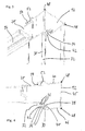
- the in the Figures 1 and 2 shown as a shower enclosure 1 trained room divider has a plurality of separating elements 2, 4, 6, which are formed as glass or plastic discs and are mounted on a frame 8.
- the frame 8 comprises two vertically mounted in the assembled state wall strips 10, 12 and two horizontal frame members 14, 16 and two Verstellancen 18, 20, the closer reference to the FIGS. 3 and 4 are explained.
- Separator 2 is firmly positioned on the frame and with his in FIG. 2 left edge firmly connected to the adjustment bar 18.
- the separating elements 4 and 6 are designed as sliding doors and mounted by means of roller arrangements movable relative to the frame 8.
- the roller assemblies 22, 24, 26 are formed on the lower frame member 16 and the upper frame member 14, respectively.
- the two wall strips 10, 12 are screwed by means of screws in a known manner with room walls.
- the wall strips 10 and 12 and the adjusting bars 18, 20 are formed as U-profiles.
- the wall bar 20 may alternatively be formed as a hollow profile with a substantially rectangular profile shape.
- the width of the adjustment bar 18, 20 is chosen so that it can be inserted between the two free legs of the wall strip 10, 20, so that the fixing element 30 can be inserted and pushed into the intermediate space, wherein the fixing element deforms elastically and / or plastically and for a bracing and fixing the adjustment bar 20 and thus the separating elements 2, 4, 6 relative to the wall bar 12 provides.
- the fixing element 30 is designed as an elongated flexible piping and extends over the entire length of the wall strip 12 as a continuous element. Alternatively, a plurality of fixing elements or piping could be used, which are not formed in one piece.
- the fixing element 30 or the piping has a cover section 32, which covers the gap between the wall strip 12 and the adjusting strip 20 in the mounted state to the outside and seals, and a fixing section 34, which ensures the mechanical tensioning and fastening of the components.
- Fixing portion 34 has a plurality of outwardly tapering in cross-section elastically deformable blades 36, of which two are arranged opposite one another. Two opposite slats form between them an angle of less than 180 ° and in cross section a kind of V-shape, the tip of which points in the Eindsch- or insertion in the assembly of the welt. In the assembled state, the blades 36 are deformed and provide a mechanical attachment.
- the fixing element or piping could also be formed as an elongate plastic strip with a substantially rectangular, cuboidal, elliptical or other shaped cross-section, for example. It could also be provided a substantially cuboidal element with projections, projections or lamellae.
- an end portion 38 is provided with two laterally projecting protrusions, which cooperates with a formed on the wall bar 12 stop 40 so that the fixing member 30 comes into abutment in a defined position and is not pressed too far.
- the length of the fixing element 30 is selected such that the cover section 32 is positioned approximately in the region of the end of the free leg of the wall strip 12.
- the wall strip 12 is provided with a plurality of corrugations 42 (see FIGS. 3 and 4 ) or other recesses, which improve the mechanical connection to the fixing element 30.
- the recesses 42 are integrally formed on a projection or thickened portion of the free leg of the wall bar 12.
- a recess 48 is provided in the transition region to the two free legs 44, 46, which extends over the entire length and serves to serve as a receptacle for a curable sealing element, such as silicone compound or the like. This achieves an effective and attractive seal between the wall strip 12 and the room wall.
- a further recess 50 is formed at its end, which is bounded by the wall bar 20 and an angle arranged on the free leg 44 sealing portion 52, the end of which can be brought into contact with the adjusting bar 20.
- a curable sealing material such as silicone or the like is injected after assembly.
- Recess 50 is arranged opposite to the fixing element 30 and extends over the entire length of the wall strip 12.
- the entire room dividing device 1, in particular the frame is substantially symmetrical, so that the shower enclosure 1 can be used as desired, be it that the frame element 8 or the frame element 16 is arranged at the top.
- the wall strip 12 is mounted on the room wall.
- the adjustment bar 20 is partially inserted into the interior of the wall strip 12 between the two free legs 44, 46 (see FIG. 3 ). Then an alignment is made. Subsequently, the piping or the fixing element 3 is pressed into the space between the wall bar 20 and leg 46 of the wall bar 12. In this case, the fins 36 deform and it comes to a contact pressure and fixation of the components relative to each other. Through the corrugations 42 it also comes to a positive connection.
- the fixing element 30 comes into contact with the stop 40 during the pushing in.
- the fixing element 30 is pressed in locally from a first, eg upper end, to the other end. For example, it starts at the top in the region of the frame element 8, and then the fastening element 30 continues to be pushed further slowly downwards.
- silicone or another sealant is pressed into the recess 15. It then hardens. If necessary, the fixing element 30 could also be removed manually or by means of tools in order to carry out disassembly.
Landscapes
- Health & Medical Sciences (AREA)
- Public Health (AREA)
- Epidemiology (AREA)
- General Health & Medical Sciences (AREA)
- Residential Or Office Buildings (AREA)
- Bathtubs, Showers, And Their Attachments (AREA)
- Domestic Plumbing Installations (AREA)
- Specific Sealing Or Ventilating Devices For Doors And Windows (AREA)
Applications Claiming Priority (1)
| Application Number | Priority Date | Filing Date | Title |
|---|---|---|---|
| DE200720017721 DE202007017721U1 (de) | 2007-12-17 | 2007-12-17 | Raumtrennvorrichtung, insbesondere Duschabtrennung |
Publications (3)
| Publication Number | Publication Date |
|---|---|
| EP2071992A2 true EP2071992A2 (fr) | 2009-06-24 |
| EP2071992A3 EP2071992A3 (fr) | 2013-10-16 |
| EP2071992B1 EP2071992B1 (fr) | 2016-09-07 |
Family
ID=39135102
Family Applications (1)
| Application Number | Title | Priority Date | Filing Date |
|---|---|---|---|
| EP08171791.0A Active EP2071992B1 (fr) | 2007-12-17 | 2008-12-16 | Cloison de séparation, notamment cloison de douche |
Country Status (3)
| Country | Link |
|---|---|
| EP (1) | EP2071992B1 (fr) |
| DE (1) | DE202007017721U1 (fr) |
| ES (1) | ES2606026T3 (fr) |
Cited By (1)
| Publication number | Priority date | Publication date | Assignee | Title |
|---|---|---|---|---|
| US20140115773A1 (en) * | 2012-11-01 | 2014-05-01 | Ideal Sanitary Ware Co., Ltd | Shower door assembly |
Citations (1)
| Publication number | Priority date | Publication date | Assignee | Title |
|---|---|---|---|---|
| DE20212447U1 (de) | 2002-08-09 | 2002-11-14 | Hüppe GmbH & Co., 26160 Bad Zwischenahn | Leistenanordnung und Raumtrennvorrichtung |
Family Cites Families (3)
| Publication number | Priority date | Publication date | Assignee | Title |
|---|---|---|---|---|
| DE4106116A1 (de) * | 1991-02-27 | 1992-09-03 | Semer Gmbh & Co Kg W | Rahmen fuer trennwaende, insbesondere fuer duschabtrennungen u. dgl. |
| DE9304078U1 (de) * | 1993-03-19 | 1993-05-13 | Koralle Sanitärprodukte GmbH, 4973 Vlotho | Duschabtrennung |
| DE10016354C2 (de) * | 2000-04-03 | 2002-02-21 | Dorma Gmbh & Co Kg | Ausgleichselement zum Ausgleichen von Toleranzen zwischen einem Einsatzelement, wie Tür, Fenster o. dgl.,und einem Durchbruch |
-
2007
- 2007-12-17 DE DE200720017721 patent/DE202007017721U1/de not_active Expired - Lifetime
-
2008
- 2008-12-16 ES ES08171791.0T patent/ES2606026T3/es active Active
- 2008-12-16 EP EP08171791.0A patent/EP2071992B1/fr active Active
Patent Citations (1)
| Publication number | Priority date | Publication date | Assignee | Title |
|---|---|---|---|---|
| DE20212447U1 (de) | 2002-08-09 | 2002-11-14 | Hüppe GmbH & Co., 26160 Bad Zwischenahn | Leistenanordnung und Raumtrennvorrichtung |
Cited By (1)
| Publication number | Priority date | Publication date | Assignee | Title |
|---|---|---|---|---|
| US20140115773A1 (en) * | 2012-11-01 | 2014-05-01 | Ideal Sanitary Ware Co., Ltd | Shower door assembly |
Also Published As
| Publication number | Publication date |
|---|---|
| EP2071992B1 (fr) | 2016-09-07 |
| EP2071992A3 (fr) | 2013-10-16 |
| ES2606026T3 (es) | 2017-03-17 |
| DE202007017721U1 (de) | 2008-02-28 |
Similar Documents
| Publication | Publication Date | Title |
|---|---|---|
| DE10136681C2 (de) | Rahmengestell | |
| EP2318780B1 (fr) | Bâti de module solaire à évacuation d'eau | |
| EP0268815A2 (fr) | Dispositif de fixation d'une fenêtre dans la baie de carrosserie d'un véhicule automobile | |
| EP3001931B1 (fr) | Dispositif de recouvrement d'obturateur | |
| EP1405979B1 (fr) | Dispositif de liaison, dispositif de recouvrement et élément de partition | |
| EP0681081A1 (fr) | Fermeture pour ouvertures dans des parois de bâtiments ou similaires | |
| EP2405095B1 (fr) | Joint de porte doté d'un élément de fixation | |
| EP0444405A2 (fr) | Ferrure pour portes ou fenêtres | |
| DE3532593A1 (de) | Extrudierter kunststoffhohlprofilstab fuer rahmen von fenstern und tueren | |
| EP1860250B1 (fr) | Profile d'étanchéité | |
| EP2071992B1 (fr) | Cloison de séparation, notamment cloison de douche | |
| EP3121360B1 (fr) | Système de fixation pour éléments de recouvrement | |
| DE102013112761A1 (de) | Haltevorrichtung für ein Gehäuse und Verfahren zur Montage des Gehäuses unter Verwendung der Haltevorrichtung | |
| EP3692611B1 (fr) | Dispositif de positionnement d'une piece plat sur un châssis d'armoire électrique et procédé correspondant | |
| AT17077U1 (de) | System zur Montage einer Fensterbank an einer Außenfassade | |
| EP2107197B1 (fr) | Dispositif de fixation pour charnières | |
| EP3064113B1 (fr) | Cloison de douche | |
| EP2754803A2 (fr) | Crémone de fenêtre ou de porte | |
| EP4275550A1 (fr) | Ensemble comprenant une nervure de support pour un fond de tiroir et un dispositif de retenue | |
| EP0799963B1 (fr) | Dispositif de fixation pour fenêtre | |
| EP3369946A1 (fr) | Cheville plate et procédé de montage d'une cheville plate dans une paroi | |
| EP2026436A2 (fr) | Profilé d'isolation | |
| DE202004013337U1 (de) | Einrichtung zur seitlichen Führung einer Verschlußanordnung für eine Öffnung in einer Wand | |
| EP1720146B1 (fr) | Dispositif d'affichage d'images | |
| EP2182157B1 (fr) | Ecran pour un espace entre un dormant de porte ou de portail et intrados |
Legal Events
| Date | Code | Title | Description |
|---|---|---|---|
| PUAI | Public reference made under article 153(3) epc to a published international application that has entered the european phase |
Free format text: ORIGINAL CODE: 0009012 |
|
| AK | Designated contracting states |
Kind code of ref document: A2 Designated state(s): AT BE BG CH CY CZ DE DK EE ES FI FR GB GR HR HU IE IS IT LI LT LU LV MC MT NL NO PL PT RO SE SI SK TR |
|
| AX | Request for extension of the european patent |
Extension state: AL BA MK RS |
|
| PUAL | Search report despatched |
Free format text: ORIGINAL CODE: 0009013 |
|
| AK | Designated contracting states |
Kind code of ref document: A3 Designated state(s): AT BE BG CH CY CZ DE DK EE ES FI FR GB GR HR HU IE IS IT LI LT LU LV MC MT NL NO PL PT RO SE SI SK TR |
|
| AX | Request for extension of the european patent |
Extension state: AL BA MK RS |
|
| RIC1 | Information provided on ipc code assigned before grant |
Ipc: A47K 3/30 20060101AFI20130911BHEP |
|
| 17P | Request for examination filed |
Effective date: 20140416 |
|
| RBV | Designated contracting states (corrected) |
Designated state(s): AT BE BG CH CY CZ DE DK EE ES FI FR GB GR HR HU IE IS IT LI LT LU LV MC MT NL NO PL PT RO SE SI SK TR |
|
| AKX | Designation fees paid |
Designated state(s): AT BE BG CH CY CZ DE DK EE ES FI FR GB GR HR HU IE IS IT LI LT LU LV MC MT NL NO PL PT RO SE SI SK TR |
|
| 17Q | First examination report despatched |
Effective date: 20150716 |
|
| GRAP | Despatch of communication of intention to grant a patent |
Free format text: ORIGINAL CODE: EPIDOSNIGR1 |
|
| INTG | Intention to grant announced |
Effective date: 20160324 |
|
| GRAS | Grant fee paid |
Free format text: ORIGINAL CODE: EPIDOSNIGR3 |
|
| GRAA | (expected) grant |
Free format text: ORIGINAL CODE: 0009210 |
|
| AK | Designated contracting states |
Kind code of ref document: B1 Designated state(s): AT BE BG CH CY CZ DE DK EE ES FI FR GB GR HR HU IE IS IT LI LT LU LV MC MT NL NO PL PT RO SE SI SK TR |
|
| REG | Reference to a national code |
Ref country code: GB Ref legal event code: FG4D Free format text: NOT ENGLISH |
|
| REG | Reference to a national code |
Ref country code: CH Ref legal event code: EP |
|
| REG | Reference to a national code |
Ref country code: IE Ref legal event code: FG4D Free format text: LANGUAGE OF EP DOCUMENT: GERMAN |
|
| REG | Reference to a national code |
Ref country code: DE Ref legal event code: R096 Ref document number: 502008014606 Country of ref document: DE |
|
| REG | Reference to a national code |
Ref country code: AT Ref legal event code: REF Ref document number: 826051 Country of ref document: AT Kind code of ref document: T Effective date: 20161015 |
|
| REG | Reference to a national code |
Ref country code: NL Ref legal event code: FP |
|
| REG | Reference to a national code |
Ref country code: LT Ref legal event code: MG4D |
|
| PG25 | Lapsed in a contracting state [announced via postgrant information from national office to epo] |
Ref country code: FI Free format text: LAPSE BECAUSE OF FAILURE TO SUBMIT A TRANSLATION OF THE DESCRIPTION OR TO PAY THE FEE WITHIN THE PRESCRIBED TIME-LIMIT Effective date: 20160907 Ref country code: NO Free format text: LAPSE BECAUSE OF FAILURE TO SUBMIT A TRANSLATION OF THE DESCRIPTION OR TO PAY THE FEE WITHIN THE PRESCRIBED TIME-LIMIT Effective date: 20161207 Ref country code: LT Free format text: LAPSE BECAUSE OF FAILURE TO SUBMIT A TRANSLATION OF THE DESCRIPTION OR TO PAY THE FEE WITHIN THE PRESCRIBED TIME-LIMIT Effective date: 20160907 Ref country code: HR Free format text: LAPSE BECAUSE OF FAILURE TO SUBMIT A TRANSLATION OF THE DESCRIPTION OR TO PAY THE FEE WITHIN THE PRESCRIBED TIME-LIMIT Effective date: 20160907 |
|
| REG | Reference to a national code |
Ref country code: FR Ref legal event code: PLFP Year of fee payment: 9 |
|
| PG25 | Lapsed in a contracting state [announced via postgrant information from national office to epo] |
Ref country code: LV Free format text: LAPSE BECAUSE OF FAILURE TO SUBMIT A TRANSLATION OF THE DESCRIPTION OR TO PAY THE FEE WITHIN THE PRESCRIBED TIME-LIMIT Effective date: 20160907 Ref country code: SE Free format text: LAPSE BECAUSE OF FAILURE TO SUBMIT A TRANSLATION OF THE DESCRIPTION OR TO PAY THE FEE WITHIN THE PRESCRIBED TIME-LIMIT Effective date: 20160907 Ref country code: GR Free format text: LAPSE BECAUSE OF FAILURE TO SUBMIT A TRANSLATION OF THE DESCRIPTION OR TO PAY THE FEE WITHIN THE PRESCRIBED TIME-LIMIT Effective date: 20161208 |
|
| REG | Reference to a national code |
Ref country code: ES Ref legal event code: FG2A Ref document number: 2606026 Country of ref document: ES Kind code of ref document: T3 Effective date: 20170317 |
|
| PG25 | Lapsed in a contracting state [announced via postgrant information from national office to epo] |
Ref country code: RO Free format text: LAPSE BECAUSE OF FAILURE TO SUBMIT A TRANSLATION OF THE DESCRIPTION OR TO PAY THE FEE WITHIN THE PRESCRIBED TIME-LIMIT Effective date: 20160907 Ref country code: EE Free format text: LAPSE BECAUSE OF FAILURE TO SUBMIT A TRANSLATION OF THE DESCRIPTION OR TO PAY THE FEE WITHIN THE PRESCRIBED TIME-LIMIT Effective date: 20160907 |
|
| PG25 | Lapsed in a contracting state [announced via postgrant information from national office to epo] |
Ref country code: IS Free format text: LAPSE BECAUSE OF FAILURE TO SUBMIT A TRANSLATION OF THE DESCRIPTION OR TO PAY THE FEE WITHIN THE PRESCRIBED TIME-LIMIT Effective date: 20170107 Ref country code: PT Free format text: LAPSE BECAUSE OF FAILURE TO SUBMIT A TRANSLATION OF THE DESCRIPTION OR TO PAY THE FEE WITHIN THE PRESCRIBED TIME-LIMIT Effective date: 20170109 Ref country code: PL Free format text: LAPSE BECAUSE OF FAILURE TO SUBMIT A TRANSLATION OF THE DESCRIPTION OR TO PAY THE FEE WITHIN THE PRESCRIBED TIME-LIMIT Effective date: 20160907 Ref country code: SK Free format text: LAPSE BECAUSE OF FAILURE TO SUBMIT A TRANSLATION OF THE DESCRIPTION OR TO PAY THE FEE WITHIN THE PRESCRIBED TIME-LIMIT Effective date: 20160907 Ref country code: BG Free format text: LAPSE BECAUSE OF FAILURE TO SUBMIT A TRANSLATION OF THE DESCRIPTION OR TO PAY THE FEE WITHIN THE PRESCRIBED TIME-LIMIT Effective date: 20161207 |
|
| REG | Reference to a national code |
Ref country code: DE Ref legal event code: R097 Ref document number: 502008014606 Country of ref document: DE |
|
| PG25 | Lapsed in a contracting state [announced via postgrant information from national office to epo] |
Ref country code: IT Free format text: LAPSE BECAUSE OF FAILURE TO SUBMIT A TRANSLATION OF THE DESCRIPTION OR TO PAY THE FEE WITHIN THE PRESCRIBED TIME-LIMIT Effective date: 20160907 |
|
| PLBE | No opposition filed within time limit |
Free format text: ORIGINAL CODE: 0009261 |
|
| STAA | Information on the status of an ep patent application or granted ep patent |
Free format text: STATUS: NO OPPOSITION FILED WITHIN TIME LIMIT |
|
| PG25 | Lapsed in a contracting state [announced via postgrant information from national office to epo] |
Ref country code: DK Free format text: LAPSE BECAUSE OF FAILURE TO SUBMIT A TRANSLATION OF THE DESCRIPTION OR TO PAY THE FEE WITHIN THE PRESCRIBED TIME-LIMIT Effective date: 20160907 |
|
| REG | Reference to a national code |
Ref country code: CH Ref legal event code: PL |
|
| 26N | No opposition filed |
Effective date: 20170608 |
|
| GBPC | Gb: european patent ceased through non-payment of renewal fee |
Effective date: 20161216 |
|
| PG25 | Lapsed in a contracting state [announced via postgrant information from national office to epo] |
Ref country code: SI Free format text: LAPSE BECAUSE OF FAILURE TO SUBMIT A TRANSLATION OF THE DESCRIPTION OR TO PAY THE FEE WITHIN THE PRESCRIBED TIME-LIMIT Effective date: 20160907 |
|
| PG25 | Lapsed in a contracting state [announced via postgrant information from national office to epo] |
Ref country code: MC Free format text: LAPSE BECAUSE OF FAILURE TO SUBMIT A TRANSLATION OF THE DESCRIPTION OR TO PAY THE FEE WITHIN THE PRESCRIBED TIME-LIMIT Effective date: 20160907 |
|
| REG | Reference to a national code |
Ref country code: IE Ref legal event code: MM4A |
|
| PG25 | Lapsed in a contracting state [announced via postgrant information from national office to epo] |
Ref country code: CH Free format text: LAPSE BECAUSE OF NON-PAYMENT OF DUE FEES Effective date: 20161231 Ref country code: LU Free format text: LAPSE BECAUSE OF NON-PAYMENT OF DUE FEES Effective date: 20161216 Ref country code: LI Free format text: LAPSE BECAUSE OF NON-PAYMENT OF DUE FEES Effective date: 20161231 |
|
| PG25 | Lapsed in a contracting state [announced via postgrant information from national office to epo] |
Ref country code: IE Free format text: LAPSE BECAUSE OF NON-PAYMENT OF DUE FEES Effective date: 20161216 Ref country code: GB Free format text: LAPSE BECAUSE OF NON-PAYMENT OF DUE FEES Effective date: 20161216 |
|
| REG | Reference to a national code |
Ref country code: FR Ref legal event code: PLFP Year of fee payment: 10 |
|
| REG | Reference to a national code |
Ref country code: AT Ref legal event code: MM01 Ref document number: 826051 Country of ref document: AT Kind code of ref document: T Effective date: 20161216 |
|
| PG25 | Lapsed in a contracting state [announced via postgrant information from national office to epo] |
Ref country code: CY Free format text: LAPSE BECAUSE OF FAILURE TO SUBMIT A TRANSLATION OF THE DESCRIPTION OR TO PAY THE FEE WITHIN THE PRESCRIBED TIME-LIMIT Effective date: 20160907 Ref country code: HU Free format text: LAPSE BECAUSE OF FAILURE TO SUBMIT A TRANSLATION OF THE DESCRIPTION OR TO PAY THE FEE WITHIN THE PRESCRIBED TIME-LIMIT; INVALID AB INITIO Effective date: 20081216 Ref country code: AT Free format text: LAPSE BECAUSE OF NON-PAYMENT OF DUE FEES Effective date: 20161216 |
|
| PG25 | Lapsed in a contracting state [announced via postgrant information from national office to epo] |
Ref country code: MT Free format text: LAPSE BECAUSE OF FAILURE TO SUBMIT A TRANSLATION OF THE DESCRIPTION OR TO PAY THE FEE WITHIN THE PRESCRIBED TIME-LIMIT Effective date: 20160907 |
|
| PGFP | Annual fee paid to national office [announced via postgrant information from national office to epo] |
Ref country code: BE Payment date: 20241216 Year of fee payment: 17 Ref country code: NL Payment date: 20241217 Year of fee payment: 17 |
|
| PGFP | Annual fee paid to national office [announced via postgrant information from national office to epo] |
Ref country code: FR Payment date: 20241218 Year of fee payment: 17 |
|
| PGFP | Annual fee paid to national office [announced via postgrant information from national office to epo] |
Ref country code: CZ Payment date: 20241203 Year of fee payment: 17 |
|
| PGFP | Annual fee paid to national office [announced via postgrant information from national office to epo] |
Ref country code: TR Payment date: 20241203 Year of fee payment: 17 |
|
| PGFP | Annual fee paid to national office [announced via postgrant information from national office to epo] |
Ref country code: ES Payment date: 20250117 Year of fee payment: 17 |
|
| PGFP | Annual fee paid to national office [announced via postgrant information from national office to epo] |
Ref country code: DE Payment date: 20260119 Year of fee payment: 18 |