EP2071993A2 - Cloison de séparation - Google Patents
Cloison de séparation Download PDFInfo
- Publication number
- EP2071993A2 EP2071993A2 EP08021587A EP08021587A EP2071993A2 EP 2071993 A2 EP2071993 A2 EP 2071993A2 EP 08021587 A EP08021587 A EP 08021587A EP 08021587 A EP08021587 A EP 08021587A EP 2071993 A2 EP2071993 A2 EP 2071993A2
- Authority
- EP
- European Patent Office
- Prior art keywords
- angle
- lower edge
- door element
- edge
- axis
- Prior art date
- Legal status (The legal status is an assumption and is not a legal conclusion. Google has not performed a legal analysis and makes no representation as to the accuracy of the status listed.)
- Withdrawn
Links
Images



Classifications
-
- A—HUMAN NECESSITIES
- A47—FURNITURE; DOMESTIC ARTICLES OR APPLIANCES; COFFEE MILLS; SPICE MILLS; SUCTION CLEANERS IN GENERAL
- A47K—SANITARY EQUIPMENT; ACCESSORIES THEREFOR, e.g. TOILET ACCESSORIES
- A47K3/00—Baths; Showers; Appurtenances therefor
- A47K3/28—Showers or bathing douches
- A47K3/30—Screens or collapsible cabinets for showers or baths
- A47K3/36—Articulated screens
-
- E—FIXED CONSTRUCTIONS
- E05—LOCKS; KEYS; WINDOW OR DOOR FITTINGS; SAFES
- E05D—HINGES OR SUSPENSION DEVICES FOR DOORS, WINDOWS OR WINGS
- E05D7/00—Hinges or pivots of special construction
- E05D7/04—Hinges adjustable relative to the wing or the frame
-
- E—FIXED CONSTRUCTIONS
- E05—LOCKS; KEYS; WINDOW OR DOOR FITTINGS; SAFES
- E05F—DEVICES FOR MOVING WINGS INTO OPEN OR CLOSED POSITION; CHECKS FOR WINGS; WING FITTINGS NOT OTHERWISE PROVIDED FOR, CONCERNED WITH THE FUNCTIONING OF THE WING
- E05F7/00—Accessories for wings not provided for in other groups of this subclass
- E05F7/08—Means for transmitting movements between vertical and horizontal sliding bars, rods, or cables
-
- A—HUMAN NECESSITIES
- A47—FURNITURE; DOMESTIC ARTICLES OR APPLIANCES; COFFEE MILLS; SPICE MILLS; SUCTION CLEANERS IN GENERAL
- A47K—SANITARY EQUIPMENT; ACCESSORIES THEREFOR, e.g. TOILET ACCESSORIES
- A47K3/00—Baths; Showers; Appurtenances therefor
- A47K3/28—Showers or bathing douches
- A47K3/30—Screens or collapsible cabinets for showers or baths
- A47K2003/305—Sealings between screen and bath- or showertub
-
- A—HUMAN NECESSITIES
- A47—FURNITURE; DOMESTIC ARTICLES OR APPLIANCES; COFFEE MILLS; SPICE MILLS; SUCTION CLEANERS IN GENERAL
- A47K—SANITARY EQUIPMENT; ACCESSORIES THEREFOR, e.g. TOILET ACCESSORIES
- A47K3/00—Baths; Showers; Appurtenances therefor
- A47K3/28—Showers or bathing douches
- A47K3/30—Screens or collapsible cabinets for showers or baths
- A47K3/36—Articulated screens
- A47K2003/365—Liftable articulated screens to be swung over the faucets and against the wall
-
- E—FIXED CONSTRUCTIONS
- E05—LOCKS; KEYS; WINDOW OR DOOR FITTINGS; SAFES
- E05Y—INDEXING SCHEME ASSOCIATED WITH SUBCLASSES E05D AND E05F, RELATING TO CONSTRUCTION ELEMENTS, ELECTRIC CONTROL, POWER SUPPLY, POWER SIGNAL OR TRANSMISSION, USER INTERFACES, MOUNTING OR COUPLING, DETAILS, ACCESSORIES, AUXILIARY OPERATIONS NOT OTHERWISE PROVIDED FOR, APPLICATION THEREOF
- E05Y2800/00—Details, accessories and auxiliary operations not otherwise provided for
- E05Y2800/67—Materials; Strength alteration thereof
- E05Y2800/672—Glass
-
- E—FIXED CONSTRUCTIONS
- E05—LOCKS; KEYS; WINDOW OR DOOR FITTINGS; SAFES
- E05Y—INDEXING SCHEME ASSOCIATED WITH SUBCLASSES E05D AND E05F, RELATING TO CONSTRUCTION ELEMENTS, ELECTRIC CONTROL, POWER SUPPLY, POWER SIGNAL OR TRANSMISSION, USER INTERFACES, MOUNTING OR COUPLING, DETAILS, ACCESSORIES, AUXILIARY OPERATIONS NOT OTHERWISE PROVIDED FOR, APPLICATION THEREOF
- E05Y2900/00—Application of doors, windows, wings or fittings thereof
- E05Y2900/10—Application of doors, windows, wings or fittings thereof for buildings or parts thereof
- E05Y2900/114—Application of doors, windows, wings or fittings thereof for buildings or parts thereof for showers
Definitions
- the invention relates to a partition, in particular shower partition, according to the features specified in the preamble of claim 1.
- the door element is pivotally mounted by means of two spaced-apart in the vertical direction to each other hinges, wherein in a first position or closed position by means of the door element, a passage, for example, from an outside space in a shower interior or vice versa, shut off. After an at least partially pivoting of the door element in a second position or in the direction of an open position, the passage is released. In the closed position, the lower edge of the door element is aligned horizontally, wherein by means of a sealing element to the bottom or to a tub edge towards a seal.
- a shower partition with adjustable pivot bearings for vertical alignment of the door element known.
- the shower partition contains three elements designed as profile rails, at the upper and lower ends of each of the two multi-part pivot bearing is arranged.
- the door element formed in particular as a glass plate is defined with its vertical longitudinal edge in a longitudinal groove of the first rail, which has a continuous inside hollow chamber, in which engages from above or below a journal of the respective pivot bearing.
- Each pivot bearing contains two bearing parts which can be adjusted relative to one another by means of a connecting element or a screw, wherein the one bearing part has said pivot pin.
- the second bearing part is connected to the second element or the second rail, which is designed as a so-called wall connection profile and is attached, for example, to a room wall of a shower room.
- wall connection profile As is known, space walls are often not aligned vertically due to on-site induced inaccuracies and thus not the said wall connection profile. Due to the two-part and adjustable design of the pivot bearing an orientation of the door member is made possible in that in the closed position of the door member whose lower edge is aligned horizontally, wherein the axis of rotation is substantially vertical.
- the door member is formed as a rectangular plate and when pivoting the door member whose lower edge is moved in a horizontal plane.
- the invention has the object further to form the partition to the effect that with a simple design and low manufacturing cost damage to the lower edge provided sealing element is at least largely avoided and a functionally reliable seal for a long life is achieved.
- the partition should require a low production and deployment effort and be manageable in a simple manner. Special loads and / or increased and / or disadvantageous wear, be it the one or more hinges or in particular of the sealing element, should be avoided.
- the partition according to the invention in particular shower partition, is characterized by a simple and yet functionally reliable construction and permanently enables a secure seal in the region of the lower edge of the door element.
- the door element and in particular its pivot bearing or hinges are arranged and / or formed such that the axis of rotation assumes a position inclined to the vertical and the lower edge of the door element and in particular the sealing element arranged there is moved obliquely upward during opening or pivoting of the door element.
- the axis of rotation is arranged at an angle smaller than 90 ° to the lower edge of the door element.
- the door element In the closed position of the door element whose lower edge and in particular the sealing element are aligned substantially horizontally, wherein the axis of rotation is not vertically aligned, but occupies an angle to the vertical, in that vertical plane in which the edge region of the door element is located.
- the door element may be substantially formed as a flat and arranged in a vertical plane plate or contain such or formed as a curved plate or contain such as for so-called round or quadrant shower partitions.
- the inclined to the vertical axis of rotation, to which the lower edge of the door member is disposed at an angle less than 90 °, is moved during pivoting of the door member on a conical lateral surface, wherein the cone axis is arranged at least approximately vertically and / or lies on said vertical and also the cone angle opens upwards. Due to the inclined arrangement of the axis of rotation, the lower edge of the door member is raised during pivoting of the door element in such a way that the lower edge is no longer oriented horizontally, but is inclined to the horizontal plane and ultimately to the ground such that one of the hinge or the Rotary axis to the free longitudinal edge of the door element opening angle is present.
- a lifting curve of the door element and / or its lower edge is predetermined and / or predetermined, wherein when opening or pivoting of the door element whose lower edge is moved upward, so that damage to the sealing element are avoided in particular tiled floor.
- the pivoting or opening of the door element is easy and easy to carry out, and moreover, a closing effect is achieved in a simple manner to the effect that the door element from the open position largely independently, but at least with little effort, enters the closed position.
- the hinges or pivot bearings are largely seal-free, since during pivoting no axial movement of their components takes place and / or abutting inclined surfaces, cam surfaces or the like are not present.
- the lifting curve for the door element is not determined by a special and / or complex and / or fault-prone design of the hinges or pivot bearing, but by the inclination of the axis of rotation.
- the inclination and / or the angle to the vertical is preferably in the range between 0.3 ° to 4 °, advantageously between 0.4 ° to 3.5 ° and in particular between 0.5 ° to 3 ° or 2 ° given, wherein before all at offset the pivot bearing, the range of 0.5 ° to 2 ° has proved to be advantageous. It should be noted that at the aforementioned inclination and / or the angle to the vertical, the angle between the axis of rotation and the lower edge of the complementary or complementary angle to an angle of 90 °.
- said free longitudinal edge is substantially vertically aligned.
- the hinges or pivot bearings are also inventively designed as pendulum hinges or pendulum pivot bearing and allow the pivoting of the door element from the closed position in both directions, ie both in the outer space and in the interior, the axis of rotation is located in particular within the door element in the region of its longitudinal edge, which associated with the hinges or pivot bearings.
- the inclination of the axis of rotation, in particular in the closed position, according to the invention can be achieved in that the pivot bearing or hinges and / or In particular, their bolts or trunnions are not exactly vertically above one another, but that the upper hinge or pivot bearing or its axis or bolt are offset or arranged offset in the direction of the free edge of the door member with respect to the axis or the bolt of the lower hinge or pivot bearing.
- a stepless adjustability of the hinges or pivot bearings and / or parts thereof may be provided.
- due to the adjustability is preferably the size or strength of the lifting curve to the requirements and / or installation conditions of the partition during their installation and optionally without further ado easily adaptable.
- the assembly method according to the invention can be carried out in a simple manner and requires no special effort or special tools.
- the door element and / or a plate forming the door element, in particular frameless glass plate be formed obliquely in the hinge region and / or tailored such that the longitudinal edge in the hinge region to the lower edge of the door member has an angle smaller than 90 °.
- This also applies to the area of the hinges or pivot bearing facing the longitudinal edge of a fixed wall element or a rail. Said angle is expedient in the range between 0.3 ° to 4 °, preferably between 0.5 ° to 3 ° or 2 °, given.
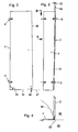
- the Fig. 1 to Fig. 4 illustrated, designed as a shower partition wall includes a door element 2 in the form of a frameless plate, in particular glass plate, and a fixed, also as a plate, in particular glass plate, formed wall element 4, which in a known manner, for example by means of screws 6, 7 and dowels or the like on a Room wall is fastened.
- the door element 2 is connected to the wall element 4 by means of two vertically spaced hinges 8, 9 pivotally connected about an axis of rotation 10, wherein the hinge 8 are provided in the region of the upper end of the partition and the hinge 9 in the region of the lower end of the partition wall.
- the hinge edge 12 facing away from the longitudinal edge 14 of the wall element 4 is aligned substantially vertically.
- the longitudinal edge 14 may be associated in a known manner a wall connection profile or the like to compensate for a slope of a room wall or the like or to make a corresponding adjustment.
- the other, the hinge region 12 associated longitudinal edge 16 of the wall element 4, however, is arranged inclined to the vertical 18 at a predetermined angle 20. Die L jossachse 16 des Wandelements 4 ist in Fig. 1 publication.
- the wall element 4 is thus not exactly rectangular or cut, but trapezoidal in such a way that the longitudinal edges 14 and 16 are not parallel to each other, but the longitudinal edge 16 in the hinge region 12 with respect to the first-mentioned longitudinal edge 14 at said angle 20 extends such that the wall element 4 at the upper end, the width 22 which is greater than the width 24 at the lower end of the wall element 4.
- the upper edge 26 and the lower edge 28 are arranged to the first-mentioned longitudinal edge 14 of the wall element 4 respectively at right angles 30.
- the associated longitudinal edge 31 of the door element 2 is inclined in the hinge region 12 to the vertical 18, namely at an angle 32 which is preferably substantially the same size as the aforementioned angle 20 of the wall element 4.
- an angle 32 which is preferably substantially the same size as the aforementioned angle 20 of the wall element 4.
- a sealing element 36 is arranged, with which takes place in the closed position, the sealing with respect to the bottom 37 of a shower room.
- the rotary or hinge axis 10 of the hinge 9 is arranged at a predetermined angle 38 to the lower edge 34 of the door element 2.
- the angle 38 is smaller by a predetermined amount than 90 °.
- the angle 38 opens in the direction of the free longitudinal edge 40 of the door element 2 and is smaller by a few degrees than a right angle of 90 °.
- the angle 38 is the supplementary angle to the aforementioned angle 32, wherein the two angles 32 and 38 together are 90 °.
- the hinge axis 10 is defined by the two axially spaced hinges 8, 9 and / or their respective hinge axes.
- the hinge axis 10 extends in an expedient manner substantially parallel to the oblique longitudinal edge 31 of the door element 2.
- the lower edge 34 and the upper edge 35 of the door element 2 have its other longitudinal edge 40 facing away from the hinge area 12 extending at right angles 30.
- this is also the case Door element 2 trapezoidal, wherein the width at the upper end or the upper edge 35 is smaller than the width at the lower end or the lower edge 34th
- the hinges 8 and 9 are preferably formed coincident and / or connected to the door member 2 and the wall member 4 such that the respective and / or common axis of rotation 10 is inclined and / or inclined to the vertical 18, and was advantageous in a given Angle 42, which in particular is at least approximately the same size as the aforementioned angle 20 and / or 32.
- the hinges 8, 9 are preferably designed as pendulum hinges, so that the door element 2 both forward, according to Fig. 1 from the drawing plane into an outdoor space, as well as to the rear, according to Fig. 1 behind the drawing plane, can be swung into an interior.
- the sealing element 36 is arranged, which in the closed position of the door element 2 according to Fig.
- Fig. 2 shows the partition with the swung in the outer space around the inclined axis of rotation 10 door element 2.
- the axis of rotation 10 to the vertical 18 by the angle 42 is arranged obliquely or inclined.
- the hinges 8, 9 are formed as known and / or simple pendulum hinges and arranged parallel to the obliquely extending longitudinal edge 16 of the wall element 4 and the oblique longitudinal edge 31 of the door element 2 or connected to the wall element 4 and the door element 2.
- the angle 42 has essentially the same angle and / or can be predefined or predetermined in the same ranges as the angle 32 between the axis of rotation 10 and the vertical 18.
- Fig. 3 shows the door in the open position by at least approximately pivoted door element 2, wherein for reasons of clarity arranged on the lower edge 34 of the door element sealing element is not shown. Due to the explained inclined position of the axis of rotation and / or the angle 38 between the axis of rotation 10 and the lower edge 34, an angle 48 is present in the open position between the lower edge 34 and the bottom 37, which opens to the free longitudinal edge 40 of the door element 2.
- the said sealing element thus lifts off when pivoting the door element 2 from the edge or bottom 37, and / or the pressure force and / or wear of the sealing element is significantly reduced.
- Fig. 4 shows the pivoted into the outer space 50 in the open position door element 2.
- dotted line 52 the passage between the outer space 50 and the interior 54 is indicated.
- dashed line 56 a curved door element of a partition is indicated with a corresponding curved or curved passage formed. It should be noted that in the closed position, the door element 2 closes the passage 52 or a curved passage and / or is located substantially in the same vertical plane as the fixed wall element 4.
- Fig. 5 shows a view of another partition
- the door element 2 is pivoted about the inclined axis to the vertical axis of rotation 10 from the illustrated closed position in both directions.
- an upper pivot bearing 58 and a lower pivot bearing 60 are arranged with not shown bearing journal and bearing parts on the fixed wall element 4, by which the inclination of the axis of rotation 10 is set to the vertical 18 at an angle 42.
- the axis of rotation 10 is again arranged at the lower edge 34 of the door element 2 in the small angle 38, which is smaller than a right angle only by a few degrees.
- the pivot bearings 58, 60 are designed to be adjustable so that the angles 42 and 38 are variable according to the requirements and preferably infinitely predetermined.
- the upper pivot bearing 58 has a arranged on the fixed wall element 4 and / or associated with this short bearing plate 62, while the lower adjustable pivot bearing 60 has a likewise connected to the fixed wall element 4 preferably long bearing plate 64.
- the journal of the upper pivot bearing 58 is relative to the journal of the lower pivot bearing 60 in a through the fixed wall element 4 and / or its longitudinal edge 16 extending vertical plane in the hinge or storage area in one predeterminable distance 66 arranged offset, whereby the inclination of the axis of rotation 10 is predetermined.
- the distance 66 is predeterminable and / or adjustable, as will be explained in more detail below.
- both the door element 2 and the wall element 4 are rectangular in shape, that is not trapezoidal as described with reference to the first embodiment.
- Fig. 6 to Fig. 8 is a partition similar to that according to Fig. 5 shown, wherein the door element 2 assumes the open position and further, instead of the illustrated wall element, a profile rail 68 is provided, which in a known manner with a room wall or the like is connectable.
- the preferably designed as a frameless plate, in particular glass plate, formed door element 2 is located after pivoting by 90 ° in the open position according to Fig. 6 in the same plane inclined to the vertical as the axis of rotation 10.
- Fig. 7 can be seen, in the open position due to the inclination of the door member 2 between the lower edge 34 and the bottom 37 of the free longitudinal edge 40 opening angle 48 is present.
- a distance 70 is present between the lower edge 34 and the bottom 37, which is predetermined as a function of the dimensions of the door element 2 and the opening angle 48 in the order of 10 mm.
- the distance 70 can be specified according to the requirements and / or installation conditions of the partition within the scope of the invention.
- Fig. 8 shows the partition according to Fig. 6
- the upper pivot bearing 58 or its pivot pin is to the lower pivot bearing 60 and the pivot pin 66 at a distance 66 in the vertical plane of the passage 52 and / or the rail 68th arranged.
- FIGS. 9 and 10 show an embodiment of the partition similar Fig. 6 with the upper pivot bearing 58 and the lower pivot bearing 60 of the door member 2 and the rail 68, wherein according to Fig. 10 the pivot bearing 58 and 60 and the pivot pin 66 have the distance from each other.
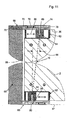
- Fig. 11 shows enlarged details X and Y according to Fig. 9 wherein the axis of rotation 10 is shown continuously for the sake of simplicity.
- the upper pivot bearing 58 is at the top
- a bearing member 74 according to double arrow 76 in the horizontal direction adjustable, suitably in a groove 78.
- the bearing member 74 is by means of suitable Clamping or fastening elements in the desired position in the bearing arm 72 can be fixed.
- the bearing part 74 has a T-shaped in cross-section and includes a downwardly directed bearing pin 80.
- a bearing housing 82 is arranged, in which a further bearing member 84 in the direction of the double arrow 86, thus arranged displaceable in the horizontal direction is.
- the bearing pin 80 of the upper bearing part 74 engages in a recess of the further bearing part 84, and the further bearing part 84 is fixed in the bearing housing 82 with suitable connecting elements, which are not shown here. It is of particular importance that in addition to the at least one adjustable bearing part 80 of the upper pivot bearing 58 or the lower pivot bearing 60, the door element 2, in particular in the bearing housing 82, the further adjustable bearing part, so that both the lower edge 34 in the closed position of the door element horizontally can be aligned, and the inclination of the axis of rotation 10 can be predetermined. According to the positions of the upper bearing part 74 and the other bearing part 84 thus the upper end of the axis of rotation 10 of the door element 2 is defined.
- the lower pivot bearing 60 is analogous to the upper pivot bearing, and above explanations apply analogously to the lower pivot bearing 60. Regardless of the particular design and / or construction of the pivot bearings 58 and 60, it is of particular importance for the invention that the upper pivot bearing 58th . Based on the storage area associated with the longitudinal edge 88 of the rail 64 or in the above-explained embodiments, the hinge region associated longitudinal edge of the fixed wall element, preferably arranged adjustable predetermined distance 66 to the lower pivot bearing 60 and thus the lower edge 34 of the door member 2 when swinging out the closed position is raised and tilted to the bottom 37 or a tub rim and attached to the lower edge 34, in Fig. 11 not shown, sealing element is lifted from the bottom 46.
Landscapes
- Health & Medical Sciences (AREA)
- Public Health (AREA)
- Epidemiology (AREA)
- General Health & Medical Sciences (AREA)
- Engineering & Computer Science (AREA)
- Mechanical Engineering (AREA)
- Hinges (AREA)
- Residential Or Office Buildings (AREA)
Applications Claiming Priority (1)
| Application Number | Priority Date | Filing Date | Title |
|---|---|---|---|
| DE200720017736 DE202007017736U1 (de) | 2007-12-17 | 2007-12-17 | Trennwand |
Publications (2)
| Publication Number | Publication Date |
|---|---|
| EP2071993A2 true EP2071993A2 (fr) | 2009-06-24 |
| EP2071993A3 EP2071993A3 (fr) | 2013-12-04 |
Family
ID=40377690
Family Applications (1)
| Application Number | Title | Priority Date | Filing Date |
|---|---|---|---|
| EP08021587.4A Withdrawn EP2071993A3 (fr) | 2007-12-17 | 2008-12-12 | Cloison de séparation |
Country Status (2)
| Country | Link |
|---|---|
| EP (1) | EP2071993A3 (fr) |
| DE (1) | DE202007017736U1 (fr) |
Cited By (1)
| Publication number | Priority date | Publication date | Assignee | Title |
|---|---|---|---|---|
| IT201800004608A1 (it) * | 2018-04-17 | 2019-10-17 | Cerniera di controllo per porte o ante inclinate |
Citations (2)
| Publication number | Priority date | Publication date | Assignee | Title |
|---|---|---|---|---|
| EP1460220A2 (fr) | 2003-03-18 | 2004-09-22 | Altura Leiden Holding B.V. | Cloison |
| GB2411112A (en) | 2004-02-19 | 2005-08-24 | Coram Showers Ltd | Adjustable shower / bath screen |
Family Cites Families (4)
| Publication number | Priority date | Publication date | Assignee | Title |
|---|---|---|---|---|
| US1563154A (en) * | 1924-01-11 | 1925-11-24 | Brager Oliver | Gravity door hinge |
| FR1386690A (fr) * | 1963-02-07 | 1965-01-22 | Eliason Refrigerator Company | Charnière pour portes battantes à fermeture automatique |
| DE29718530U1 (de) * | 1997-10-18 | 1997-12-18 | Kermi Gmbh, 94447 Plattling | Duscheinheit |
| NL1013586C2 (nl) * | 1999-11-16 | 2001-05-17 | Myrpharma B V | Zelfsluitende deur voorzien van een zelfsluitend schaniermechanisme alsmede een dergelijk zelfsluitend scharniermechanisme. |
-
2007
- 2007-12-17 DE DE200720017736 patent/DE202007017736U1/de not_active Expired - Lifetime
-
2008
- 2008-12-12 EP EP08021587.4A patent/EP2071993A3/fr not_active Withdrawn
Patent Citations (2)
| Publication number | Priority date | Publication date | Assignee | Title |
|---|---|---|---|---|
| EP1460220A2 (fr) | 2003-03-18 | 2004-09-22 | Altura Leiden Holding B.V. | Cloison |
| GB2411112A (en) | 2004-02-19 | 2005-08-24 | Coram Showers Ltd | Adjustable shower / bath screen |
Cited By (2)
| Publication number | Priority date | Publication date | Assignee | Title |
|---|---|---|---|---|
| IT201800004608A1 (it) * | 2018-04-17 | 2019-10-17 | Cerniera di controllo per porte o ante inclinate | |
| EP3556980A1 (fr) * | 2018-04-17 | 2019-10-23 | In & Tec S.r.l. | Charnière pour la commande de portes ou de feuilles de porte inclinées |
Also Published As
| Publication number | Publication date |
|---|---|
| EP2071993A3 (fr) | 2013-12-04 |
| DE202007017736U1 (de) | 2009-04-30 |
Similar Documents
| Publication | Publication Date | Title |
|---|---|---|
| DE69832772T2 (de) | Schiebefenster- und Türanordnung | |
| DE202014102405U1 (de) | Verriegelungsvorrichtung für Schwenkschiebetüren von Fahrzeugen des öffentlichen Personenverkehrs; Schwenkschiebetür mit Verriegelungsvorrichtung | |
| DE8308201U1 (de) | Zumindest an seinem unteren ende ausstellbarer fluegel eines fensters, einer tuer od. dgl. | |
| EP3168398B1 (fr) | Charnière dissimulée pour portes, fenêtres ou composants similaires | |
| EP2708692B1 (fr) | Ferrure destinée à être agencée de façon cachée dans la feuillure entre un battant et un cadre de fenêtre, de porte ou analogue | |
| DE102007054476B4 (de) | Kulissenanordnung | |
| DE102008028633B4 (de) | Antriebsanordnung für einen Schwenkflügel | |
| DE3104973A1 (de) | "aufschraubband, insbesondere fuer schwere fenster- oder tuerfluegel mit kunststoffprofilen" | |
| DE102007024742B4 (de) | Fenster oder Tür mit einer Entlastungseinrichtung | |
| DE102011085177A1 (de) | Antriebssystem für ein KFZ-Dachsystem | |
| DE102007039069A1 (de) | Fenster sowie Fensterbeschlag | |
| EP2071993A2 (fr) | Cloison de séparation | |
| DE60010806T2 (de) | Verdeckter Öffnungsbeschlag für Drehflügeltür oder -Fenster | |
| DE2949082A1 (de) | Einrichtung zum anbringen eines schuerfwerkzeuges am vorderende eines fahrzeuges | |
| EP2013045A1 (fr) | Fenetre levable | |
| EP1176276A1 (fr) | Structure de verrouillage autoverrouillable avec possibilité de réglage | |
| EP1316665A2 (fr) | Bras de compas pour battant articulé de fenêtre, porte ou similaire | |
| DE102004035286A1 (de) | Neigungsverstellung der Rückenlehne eines Badelifters | |
| EP3871575A1 (fr) | Charnière | |
| DE202012000152U1 (de) | Beschlaganordnung | |
| DE102004024842B3 (de) | Scharnierbeschlag für eine KFZ-Tür | |
| EP2225987B1 (fr) | Système de charnière pour parois de séparation et procédé d'équipement d'un système de charnière | |
| DE102006042155B4 (de) | Ladebordwand für ein Transportfahrzeug | |
| DE102011013268B4 (de) | Türscharnier mit Selbsthaltefunktion | |
| DE202024106681U1 (de) | Drehbeschlag für eine Tür, ein Tor oder ein drehbar befestigtes Bauteil |
Legal Events
| Date | Code | Title | Description |
|---|---|---|---|
| PUAI | Public reference made under article 153(3) epc to a published international application that has entered the european phase |
Free format text: ORIGINAL CODE: 0009012 |
|
| AK | Designated contracting states |
Kind code of ref document: A2 Designated state(s): AT BE BG CH CY CZ DE DK EE ES FI FR GB GR HR HU IE IS IT LI LT LU LV MC MT NL NO PL PT RO SE SI SK TR |
|
| AX | Request for extension of the european patent |
Extension state: AL BA MK RS |
|
| RIN1 | Information on inventor provided before grant (corrected) |
Inventor name: DER ERFINDER HAT AUF SEINE NENNUNG VERZICHTET. |
|
| PUAL | Search report despatched |
Free format text: ORIGINAL CODE: 0009013 |
|
| AK | Designated contracting states |
Kind code of ref document: A3 Designated state(s): AT BE BG CH CY CZ DE DK EE ES FI FR GB GR HR HU IE IS IT LI LT LU LV MC MT NL NO PL PT RO SE SI SK TR |
|
| AX | Request for extension of the european patent |
Extension state: AL BA MK RS |
|
| RIC1 | Information provided on ipc code assigned before grant |
Ipc: A47K 3/36 20060101AFI20131030BHEP |
|
| AKX | Designation fees paid |
Designated state(s): AT BE BG CH CY CZ DE DK EE ES FI FR GB GR HR HU IE IS IT LI LT LU LV MC MT NL NO PL PT RO SE SI SK TR |
|
| STAA | Information on the status of an ep patent application or granted ep patent |
Free format text: STATUS: THE APPLICATION IS DEEMED TO BE WITHDRAWN |
|
| 18D | Application deemed to be withdrawn |
Effective date: 20140605 |