EP2071999B1 - Dispositif de nettoyage d'enveloppes de balais à franges - Google Patents
Dispositif de nettoyage d'enveloppes de balais à franges Download PDFInfo
- Publication number
- EP2071999B1 EP2071999B1 EP07024389A EP07024389A EP2071999B1 EP 2071999 B1 EP2071999 B1 EP 2071999B1 EP 07024389 A EP07024389 A EP 07024389A EP 07024389 A EP07024389 A EP 07024389A EP 2071999 B1 EP2071999 B1 EP 2071999B1
- Authority
- EP
- European Patent Office
- Prior art keywords
- cleaning
- suction
- region
- mop
- mechanical stripping
- Prior art date
- Legal status (The legal status is an assumption and is not a legal conclusion. Google has not performed a legal analysis and makes no representation as to the accuracy of the status listed.)
- Not-in-force
Links
Images

Classifications
-
- A—HUMAN NECESSITIES
- A47—FURNITURE; DOMESTIC ARTICLES OR APPLIANCES; COFFEE MILLS; SPICE MILLS; SUCTION CLEANERS IN GENERAL
- A47L—DOMESTIC WASHING OR CLEANING; SUCTION CLEANERS IN GENERAL
- A47L13/00—Implements for cleaning floors, carpets, furniture, walls, or wall coverings
- A47L13/10—Scrubbing; Scouring; Cleaning; Polishing
- A47L13/50—Auxiliary implements
- A47L13/502—Shakers for dust-cloths or mops; Bumpers therefor
Definitions
- the invention relates to a device for cleaning mop covers by suction in the mounted state on a mop holder.
- mops For professional cleaning of smooth floor coverings, such as plastic floors, tiles or parquet floors, so-called mops are typically used. These mops typically comprise a textile area which serves to clean the floor coverings.
- the textile area is usually formed from textile fibers which are formed in fringes or in loop form on the mop.
- Wiping mops are usually clamped in the form of a mop cover on a mop holder so that they rest substantially with their entire textile support surface on the smooth floor covering to be cleaned.
- Mop covers of different properties can typically be clamped and used with the same mop holder.
- the mop cover itself serves to solve when cleaning the smooth floor coverings adhering to the soil dirt and absorb in the fibers of the mop cover and hold until the dirt is then either discharged into the vessel with cleaning liquid or brushing out of the mop, shake, aspirate or wash out.
- the textile fibers of the textile area which are usually in fringe or loop form, act in principle like the bristles of a brush, with which the smooth floor covering is treated. As a result of this brushing effect, the protection adheres to the fiber surface or in the respective spaces between the fibers of the mop cover. If so much dirt sticks in the mop cover that this mop cover, which acts like a dirt store, can no longer absorb dirt, the mop cover must be cleaned again to allow further cleaning of the floor.
- the cleaning can be done either manually in the clamped state of the mop cover on the respective mop holder, or in a detached from the mop holder state. In the removed state, the mop is washed, for example, in a washing machine.
- the mop cover When used for the dry cleaning of smooth floor coverings, the mop cover must be shaken, brushed, combed out or after a certain period of cleaning to solve the dirt stored in the mop cover be sucked off, either in the clamped state or separated from the separate mop holder state, which requires an additional step by the cleaning power.
- US 3,531,818 refers to a cleaning device for dust mops, in which the mop cover can be sucked through a connected vacuum cleaner.
- US 2,159,176 refers to a cleaning device for cleaning mop covers.
- EP 1 068 830 A2 refers to a device for cleaning mop covers in the clamped state on a mop holder by suction, comprising a housing, one or more recesses in the housing for insertion and removal and / or for performing the mop cover.
- US 2,466,771 refers to a device for cleaning dust mops.
- the invention has for its object to provide a device for cleaning mop covers by suction, in which the cleaning performance is further improved.
- the invention is based on the idea of specifying a device for cleaning mop covers by suction in the mounted state on a mop holder, in which at least one cleaning area for cleaning one side of the mop cover is present.
- a suction area for applying a suction vacuum is provided in a partial area of the cleaning area.
- at least two mechanical stripping means are provided, which serve for mechanical cleaning of the mop cover.
- a mechanical cleaning of the mop covers in particular by means of the mechanical stripping possible stripping / brushing / combing out can be achieved simply by passing the mop cover on the mechanical stripping.
- the suction suction of the dissolved in this way by means of mechanical stripping dirt. Because the suction region is provided only in a partial region of the cleaning region and therefore has only a relatively small opening, relatively high negative pressure can be built up, so that the applied suction power is increased on the mop cover itself.
- the device for cleaning mop covers is provided on a cleaning trolley, to which an actuating device for switching on and off the nipple, in particular a battery sucker, is provided.
- the actuating device simultaneously provides a braking effect, so that the cleaning carriage equipped with this actuating device is held substantially stationary during the actuation of the actuating device.
- a cleaning force can bring the mop into the device for cleaning mop covers without the cleaning trolley changing its position. This is particularly advantageous because of Mop must be pulled over the cleaning area to achieve a cleaning and a fixed cleaning area is helpful.
- the actuating device is preferably operated by means of a foot.
- the at least two mechanical stripping means extend into the suction area. In this way it can be achieved that also in the suction area, a mechanical stripping of the dirt can take place, similar to a carpet suction nozzle of a vacuum cleaner.
- the cleaning area is inclined substantially relative to the horizontal. For example, at an inclination of 45 ° relative to the horizontal is achieved that the mop cover is pressed together with the mop holder by its own weight on the mechanical stripping and thus an efficient and power-saving cleaning of the mop cover can be achieved by the cleaning power. Due to the inclination can be further achieved that dust particles and other dirt slip along the inclined plane and collect in a lower area of the cleaning area.
- the suction area is correspondingly mounted in a lower portion of the cleaning area, so that the incoming dirt particles can be sucked off immediately.
- the mechanical stripping means are preferably designed in the form of rigid or elastic lamellae, brushes, rollers or other jaws. In this way it is possible to adapt the respective mechanical stripping means to the respective mop cover or to achieve an embodiment of the mechanical stripping means corresponding to the respective application.
- the mechanical stripping means preferably delimit at least one air-guiding gap connected to the suction region in such a way that the negative pressure built up in the suction area in the air guide gap promotes possibly arriving dirt particles in the direction of the suction area, so that the dirt particles can be sucked off quickly and cleanly.
- the cleaning area is designed as a substantially planar bearing surface on which the mechanical stripping means are mounted and into which the suction area is introduced.
- a substantially planar support surface preferably an inclined planar support surface
- the respective mop can be easily applied and guided, so that the cleaning force can perform an ergonomic cleaning of the mop cover.
- the cleaning area is introduced only in a partial area of the essentially planar support surface, so that a part of the planar support surface located outside this partial area merely serves as a guide surface for the mop cover.
- a guide device is further provided at the upper or lower end of the flat support surface to guide the clamped mop over the flat support surface in such a way that it optimally comes into contact with the cleaning region and interacts with it for cleaning.
- the mechanical stripping agents are charged and / or recharged in such a way that they attract the dust particles electrostatically and thereby further improve the cleaning performance of the device for cleaning mop covers.
- two substantially opposite cleaning areas are provided, through which a clamped mop cover for simultaneous cleaning of two mutually opposite sides of the mop cover can be performed.
- the cleaning areas are substantially vertical and are aligned parallel to each other.
- the suction area is arranged centrally in the respective cleaning areas. Due to the central arrangement, a constant cleaning performance is achieved independently of the direction of execution of the mop cover. In these embodiments, for example, an efficient cleaning of mop covers of professional cleaning companies is possible, in which a simultaneous cleaning of both sides of a mop cover in a single operation is made possible.
- a third cleaning area which is perpendicular to the first and the second cleaning area, may be provided such that the three cleaning areas are arranged substantially in a U-shape. In this way, in addition, an edge region of the mop cover can be cleaned.
- a guide device for feeding the mop cover in the clamped state to the two cleaning areas is helpful in order to achieve a simple and trouble-free feeding or performing the mop cover and to prevent snagging or tilting.
- the cleaning area in particular the suction area, is provided with a connecting device for a suction device.
- a connecting device for a suction device is designed as a tube with stepped diameters, so that conventional suction devices, which usually have tubular connecting pieces of different diameters, can be accommodated.
- a water separator is advantageously provided in the device for cleaning mop covers and / or in a suction line between the cleaning area or suction area and the suction device.
- a water separator By providing a water separator, the suctioned in cleaning a wet or wet mop cover over the suction water collected in the water and not fed into the suction device.
- the combination of conventional suction devices with the device for cleaning mop covers is also possible when used with wet mop covers.
- the device for cleaning mop covers can be combined in an economical manner with existing cleaning systems.
- the water separator is integrated into the device for cleaning mop covers.
- the device for cleaning mop covers is coupled to a battery suction device, in particular a battery vacuum cleaner, which is provided together with the device for cleaning on a cleaning trolley.
- a particularly flexible and mobile device for cleaning mop covers is provided, which is independent of an external vacuum cleaner or the power grid. This is particularly advantageous in large buildings, since no power cord must be carried and repositioned here.
- the actuating device is in the form of a vertically pivotable pedal which on the Cleaning cart or provided on the device for cleaning mop covers provided.
- the braking effect is achieved by the provision of a region of increased friction under the pedal, in particular by the provision of a rubber layer or brake pads, when the pedal is down to the ground.
- a cost-effective and safe device is provided, by means of which, for the one hand, the sucker for applying the Absaugunter horrs is operated on the suction, and on the other hand, the respective cleaning trolley can be kept stationary at the same time. This provides efficient operation of the device for cleaning mop covers.
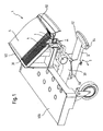
- FIG. 1 shows in a perspective, schematic and partially sectional view of a device 1 for cleaning mop covers, which is mounted on a cleaning cart 100.
- the device 1 for cleaning mop covers by suction in the clamped state on a mop holder has a single cleaning area 2 for cleaning a side of the (not shown here) mop cover.
- the cleaning area 2 has in a partial area a suction area 3 for applying a suction vacuum to the mop cover.
- at least two mechanical stripping means 4 are provided in the cleaning area 2.
- the mechanical stripping means 4 can be provided as elastic or rigid lamellae, brushes or rollers.
- the mechanical stripping means 4 delimit air guide gaps 30 connected to the suction region 3, which inter alia serve to convey the dirt removed by the mechanical stripping means 4 into the suction region 3.
- the cleaning area 2 is in the embodiment shown in FIG. 1 in turn provided in a substantially centrally arranged portion of a substantially flat support surface 5.
- the flat bearing surface 5 is inclined relative to the horizontal, approximately at an angle of 45 °, and is inclined away from the cleaning cart 100, so typically to the respective cleaning power.
- the mechanical stripping means 4 are shown in the embodiment shown as extending transversely to the planar support surface 5, electrostatically active slats, for example made of rubber or a polymer material, which are in a variety (shown eight slats) are present.
- the mechanical stripping 4 may be formed, for example, in the form of rigid, fixed blades, brush elements or rollers and serve, inter alia, to mechanically treat the mop cover so that adhering to the mop cover dirt by the flexing, which make the lamellae on the cover , is stripped.
- the suction region 3 is arranged in a lower region of the essentially opposite inclined support surface 5 in such a way that dirt particles which are stripped off the mop cover by the mechanical stripping means 4 trickle or suck down by gravity and through the suction winch be and can then be included in the Absaug Colour 3.
- the support surface which is inclined substantially relative to the horizontal, has a guide device 50 on its upper and lower edges, which serves to pull the mop cover in a targeted and guided manner over the cleaning device 2.
- the mechanical stripping means 4 extend simultaneously over the suction region.
- a grate is formed, as it were, above the suction area such that Dirt particles can be sucked into the suction area.
- the mop cover rests on the support surface, which is inclined substantially relative to the horizontal, and is pulled over the cleaning region 2 by the cleaning force, guided by the guide devices 50.
- the cleaning region 2 serves to act on the mop cover in a manner similar to a vacuum cleaner nozzle.
- connection 30 for a sucker is furthermore shown, via which connection the suction region 3 is provided with the suction vacuum.
- a sucker may in particular also be a battery sucker, with which an increased independence of the cleaning cart 100 with respect to power cables can be achieved.
- a water separator is provided either in the device for cleaning mop covers itself or in the connection line / suction line which leads to the suction device.
- the water separator ensures that even when using a typical (dry) teat reliable operation can also take place when cleaning wet or wet mop covers.
- the water or liquid extracted from the respective mop cover is collected by means of the water separator, so that the water or the liquid can also be disposed of centrally.
- the water separator is integrated into the housing of the device for cleaning mop covers.
- an actuating device 6 is provided, which is provided in the form of a foot pedal, which can be pivoted in the direction of the arrow S about a pivot axis 60 around so that the underside of the actuator 6, in particular the pedal portion 62 can come into contact with the floor.
- a material with increased friction 64 is provided, for example in the form of rubber nubs.
- the cleaning trolley can be kept substantially stationary, in particular due to the friction against the floor caused by the rubber knobs 64.
- the actuator 6 is used to turn on the suction device, so that only when using a battery sucker battery performance is only needed if actually the mop cover to be cleaned.
- FIG. 2 a device for cleaning mop covers 1 'is shown in a second embodiment.
- the respective suction area 3' is arranged centrally in a partial area of the respective cleaning area 2 ', 2".
- a third cleaning area 2 '" is provided perpendicular to the first cleaning area 2' and the second cleaning area 2", which is arranged in the bottom area, as it were.Also in the third cleaning area 2 '' 'are mechanical stripping means and a suction area through which dirt is sucked can be provided.
- FIG. 2 it is immediately clear that by providing the two cleaning areas 2 'lying opposite one another, 2 "and the third cleaning area 2 '"' perpendicular thereto can be simultaneously cleaned by the mop cover on a front on a back and a front side.
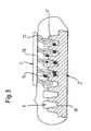
- FIG. 3 is a sectional view along the line AB of FIG. 2 shown by the cleaning region 2 ', in which the mechanical stripping means in the form of the lamellae 4' are clearly visible.
- a mop 7 with a holder 70 and the loop-shaped textile region 72.
- Schematically dirt 74 is indicated, which 'gets stuck in the interstices of the slats 4.
- Suction areas 3 ' are indicated schematically as seen from above.
- the mechanical stripping means in the form of electrostatic materials are provided so that dirt adheres to the blades. As a result, a further increased cleaning effect can be achieved.
- an air guide gap 30 is formed, which, in particular at the conclusion by a mop 7, an air flow in the direction of the respective suction 3' causes such that the trapped in the fins dirt in the suction area 3 'is pulled in.
Landscapes
- Cleaning Implements For Floors, Carpets, Furniture, Walls, And The Like (AREA)
- Filters For Electric Vacuum Cleaners (AREA)
- Cleaning In General (AREA)
Claims (21)
- Dispositif (1) pour le nettoyage d'enveloppes de balais à franges (7), par aspiration en un état tendu sur un support de balais à franges, comprenant :au moins une zone de nettoyage (2), pour nettoyer chaque fois une face de l'enveloppe de balai à franges, la zone de nettoyage (2) présentant au moins deux moyens de raclage (4) mécaniques et, dans une zone partielle, une zone d'aspiration (3), pour appliquer un vide d'aspiration, etle dispositif étant prévu sur un chariot de nettoyage (100), caractérisé en ce qu'un dispositif d'actionnement (6) est prévu pour la mise en service/hors service du dispositif d'aspiration,le dispositif d'actionnement (6) fournissant simultanément un effet de freinage pour le chariot de nettoyage (100).
- Dispositif selon la revendication 1, dans lequel les moyens de raclage (4) mécaniques s'étendent dans la zone d'aspiration (3).
- Dispositif selon la revendication 1 ou la revendication 2, dans lequel la zone de nettoyage (2) est sensiblement inclinée par rapport à l'horizontale, en particulier disposée sous un angle de 45° ou perpendiculairement.
- Dispositif selon la revendication 3, dans lequel la zone d'aspiration (3) est prévue dans le tronçon inférieur de la zone d'aspiration (2).
- Dispositif selon l'une des revendications précédentes, dans lequel les moyens de raclage (4) mécaniques sont prévus sous la forme de lamelles, brosses ou rouleaux élastiques ou rigides.
- Dispositif selon l'une des revendications précédentes, dans lequel la zone de nettoyage est disposée dans une surface de pose (5) sensiblement inclinée par rapport à l'horizontale.
- Dispositif selon la revendication 6, dans lequel les moyens de raclage (4) mécaniques sont montés sur la surface de pose et la zone d'aspiration (3) est insérée dans la surface de pose.
- Dispositif selon la revendication 6 ou 7, dans lequel la zone de nettoyage (2) est prévue seulement dans une zone partielle de la surface de pose (5).
- Dispositif selon l'une des revendications 6 à 8, dans lequel un dispositif de guidage (50) est prévu, pour guider le balai à franges tendu le long de la surface de pose (5).
- Dispositif selon l'une des revendications précédentes, dans lequel les moyens de raclage (4) mécaniques agissent de manière électrostatique.
- Dispositif selon l'une des revendications précédentes, dans lequel deux zones de nettoyage (2', 2") sensiblement opposées sont prévues pour faire passer un balai à franges tendu, de manière à assurer un nettoyage simultané des deux faces du balai à franges.
- Dispositif selon la revendication 11, dans lequel les zones de nettoyage (2', 2") sont disposées sensiblement verticalement.
- Dispositif selon la revendication 11 ou 12, dans lequel la zone d'aspiration (3') est disposée sensiblement centralement dans la zone de nettoyage (2', 2").
- Dispositif selon l'une des revendications 11 à 13, dans lequel une troisième zone de nettoyage est prévue, perpendiculairement aux première et deuxième zones de nettoyage (2', 2"), en particulier les trois zones de nettoyage (2', 2", 2"') sont disposées en forme de U.
- Dispositif selon l'une des revendications précédentes, dans lequel un dispositif de guidage (50) est prévu, pour l'amenée de l'enveloppe de balai à franges aux zones de nettoyage (2', 2", 2"').
- Dispositif selon l'une des revendications précédentes, dans lequel la zone d'aspiration (3) est couplée à un dispositif d'aspiration, en particulier à un aspirateur fonctionnant sur accumulateur.
- Dispositif selon la revendication 16, dans lequel la zone d'aspiration (3) est couplée au dispositif d'aspiration par l'intermédiaire d'un tube ayant des diamètres différents.
- Dispositif selon l'une des revendications précédentes, dans lequel un séparateur d'eau est prévu dans une conduite d'aspiration, entre la zone d'aspiration (3) et un dispositif d'aspiration.
- Dispositif selon la revendication 18, dans lequel le séparateur d'eau est intégré dans un boîtier du dispositif de nettoyage d'enveloppes de balais à franges.
- Dispositif selon l'une des revendications précédentes, dans lequel le dispositif d'actionnement (6) est prévu sous la forme d'une pédale (62) susceptible de pivoter en direction verticale, pédale susceptible de pivoter jusqu'au sol et présentant, sur sa face inférieure, un matériau à coefficient de friction élevé, en particulier des tétons en caoutchouc (64).
- Dispositif selon l'une des revendications précédentes, dans lequel les moyens de raclage (4) mécaniques délimitent au moins un intervalle de guidage d'air (30) relié à la zone d'aspiration (3).
Priority Applications (3)
| Application Number | Priority Date | Filing Date | Title |
|---|---|---|---|
| AT07024389T ATE497717T1 (de) | 2007-12-17 | 2007-12-17 | Vorrichtung zur reinigung von moppbezügen |
| EP07024389A EP2071999B1 (fr) | 2007-12-17 | 2007-12-17 | Dispositif de nettoyage d'enveloppes de balais à franges |
| DE502007006471T DE502007006471D1 (de) | 2007-12-17 | 2007-12-17 | Vorrichtung zur Reinigung von Moppbezügen |
Applications Claiming Priority (1)
| Application Number | Priority Date | Filing Date | Title |
|---|---|---|---|
| EP07024389A EP2071999B1 (fr) | 2007-12-17 | 2007-12-17 | Dispositif de nettoyage d'enveloppes de balais à franges |
Publications (2)
| Publication Number | Publication Date |
|---|---|
| EP2071999A1 EP2071999A1 (fr) | 2009-06-24 |
| EP2071999B1 true EP2071999B1 (fr) | 2011-02-09 |
Family
ID=39273883
Family Applications (1)
| Application Number | Title | Priority Date | Filing Date |
|---|---|---|---|
| EP07024389A Not-in-force EP2071999B1 (fr) | 2007-12-17 | 2007-12-17 | Dispositif de nettoyage d'enveloppes de balais à franges |
Country Status (3)
| Country | Link |
|---|---|
| EP (1) | EP2071999B1 (fr) |
| AT (1) | ATE497717T1 (fr) |
| DE (1) | DE502007006471D1 (fr) |
Family Cites Families (9)
| Publication number | Priority date | Publication date | Assignee | Title |
|---|---|---|---|---|
| US1898887A (en) * | 1931-07-01 | 1933-02-21 | Arthur P S Naul | Mop cleaner and dust pan |
| US2159176A (en) * | 1936-07-17 | 1939-05-23 | David V Nelson | Cleaning apparatus |
| US2466771A (en) * | 1944-02-22 | 1949-04-12 | James A Jones | Dust mop cleaner |
| US3015121A (en) * | 1960-03-14 | 1962-01-02 | Futuronic Dev Company | Brush cleaner |
| US3056993A (en) * | 1961-07-24 | 1962-10-09 | Emory W Lewis | Vacuum cleaner attachment |
| US3531818A (en) * | 1968-09-11 | 1970-10-06 | William Imm | Dust mop cleaner |
| JPH09313414A (ja) * | 1996-06-03 | 1997-12-09 | Yuda:Kk | ウエットバキュームクリーナー用のモップ絞り用アタッチメント |
| DE19932536A1 (de) | 1999-07-13 | 2001-01-25 | Vermop Salmon Gmbh | Einrichtung zur Reinigung von Mopbezügen |
| US7024723B2 (en) * | 2001-06-15 | 2006-04-11 | Headwaters R&D, Inc. | Duster cleaning member for a vacuum cleaner |
-
2007
- 2007-12-17 DE DE502007006471T patent/DE502007006471D1/de active Active
- 2007-12-17 EP EP07024389A patent/EP2071999B1/fr not_active Not-in-force
- 2007-12-17 AT AT07024389T patent/ATE497717T1/de active
Also Published As
| Publication number | Publication date |
|---|---|
| EP2071999A1 (fr) | 2009-06-24 |
| DE502007006471D1 (de) | 2011-03-24 |
| ATE497717T1 (de) | 2011-02-15 |
Similar Documents
| Publication | Publication Date | Title |
|---|---|---|
| DE60300480T2 (de) | Oberflächenreinigungsvorrichtung | |
| DE69120961T2 (de) | Teppich-bürstsaugmaschine mit musterorientiertem staubsaugermundstück | |
| DE3526655C2 (de) | Kehrwalze für eine Kehrmaschine | |
| DE212015000249U1 (de) | Bodenreinigungsgerät | |
| EP0265466B1 (fr) | Brosse a fibres veloutees pour le nettoyage des tissus textiles | |
| DE202009013434U1 (de) | Vorrichtung zur Fußboden-Nassreinigung | |
| DE102021006683B4 (de) | Reinigungssystem mit Saugroboter und Reinigungsstation | |
| EP2014212B1 (fr) | Association d'un suceur d'aspirateur et d'un chiffon, ainsi que chiffon et procédé de nettoyage humide de planchers | |
| DE102021131524B4 (de) | Reinigungssystem mit Saugroboter und Reinigungsstation | |
| DE202024101949U1 (de) | Baugruppe zur Reinigung von verwickelten Gegenständen, Reinigungsbaugruppe und Oberflächenreinigungsgerät | |
| DE202024101971U1 (de) | Reinigungsbaugruppe und Reinigungsroboter | |
| EP1194052B1 (fr) | Brosse de nettoyage pour tapis | |
| EP2823746B1 (fr) | Dispositif de nettoyage pour le nettoyage humide des sols | |
| DE102007014548A1 (de) | Verfahrbares Haushalts-Bodenfeuchtreinigungsgerät | |
| DE102014117418A1 (de) | Bodendüse für ein Bodenpflegegerät und Verfahren zum Herstellen einer Bodendüse für ein Bodenpflegegerät | |
| DE102017125085A1 (de) | Bodenpflegegerät | |
| EP2071999B1 (fr) | Dispositif de nettoyage d'enveloppes de balais à franges | |
| WO2011109917A1 (fr) | Plateau serpillière avec une serpillière associée permettant une pose sans l'aide des mains | |
| EP3586709B1 (fr) | Buse de sol pour aspirateur et aspirateur | |
| DE202024101407U1 (de) | Reinigungsbaugruppe und Reinigungsroboter | |
| DE202024104090U1 (de) | Reinigungsbaugruppe und Reinigungsroboter | |
| DE102017113466A1 (de) | Bodendüse für Staubsauger und Staubsauger | |
| DE102007033489B4 (de) | Vorsatzteil eines Reinigungsgeräts, insbesondere Saugdüsen oder Bürstenkopf, sowie Reinigungsgerät | |
| DE102021004575A1 (de) | Saugdüse | |
| EP4144273B1 (fr) | Elément supplémentaire pour un appareil de nettoyage de sol et appareil de nettoyage de sol |
Legal Events
| Date | Code | Title | Description |
|---|---|---|---|
| PUAI | Public reference made under article 153(3) epc to a published international application that has entered the european phase |
Free format text: ORIGINAL CODE: 0009012 |
|
| AK | Designated contracting states |
Kind code of ref document: A1 Designated state(s): AT BE BG CH CY CZ DE DK EE ES FI FR GB GR HU IE IS IT LI LT LU LV MC MT NL PL PT RO SE SI SK TR |
|
| AX | Request for extension of the european patent |
Extension state: AL BA HR MK RS |
|
| 17P | Request for examination filed |
Effective date: 20091222 |
|
| 17Q | First examination report despatched |
Effective date: 20100126 |
|
| AKX | Designation fees paid |
Designated state(s): AT BE BG CH CY CZ DE DK EE ES FI FR GB GR HU IE IS IT LI LT LU LV MC MT NL PL PT RO SE SI SK TR |
|
| RAP1 | Party data changed (applicant data changed or rights of an application transferred) |
Owner name: VERMOP SALMON GMBH |
|
| GRAP | Despatch of communication of intention to grant a patent |
Free format text: ORIGINAL CODE: EPIDOSNIGR1 |
|
| GRAS | Grant fee paid |
Free format text: ORIGINAL CODE: EPIDOSNIGR3 |
|
| GRAA | (expected) grant |
Free format text: ORIGINAL CODE: 0009210 |
|
| AK | Designated contracting states |
Kind code of ref document: B1 Designated state(s): AT BE BG CH CY CZ DE DK EE ES FI FR GB GR HU IE IS IT LI LT LU LV MC MT NL PL PT RO SE SI SK TR |
|
| REG | Reference to a national code |
Ref country code: GB Ref legal event code: FG4D Free format text: NOT ENGLISH |
|
| REG | Reference to a national code |
Ref country code: CH Ref legal event code: EP |
|
| REG | Reference to a national code |
Ref country code: IE Ref legal event code: FG4D Free format text: LANGUAGE OF EP DOCUMENT: GERMAN |
|
| REF | Corresponds to: |
Ref document number: 502007006471 Country of ref document: DE Date of ref document: 20110324 Kind code of ref document: P |
|
| REG | Reference to a national code |
Ref country code: DE Ref legal event code: R096 Ref document number: 502007006471 Country of ref document: DE Effective date: 20110324 |
|
| REG | Reference to a national code |
Ref country code: NL Ref legal event code: VDEP Effective date: 20110209 |
|
| LTIE | Lt: invalidation of european patent or patent extension |
Effective date: 20110209 |
|
| PG25 | Lapsed in a contracting state [announced via postgrant information from national office to epo] |
Ref country code: LT Free format text: LAPSE BECAUSE OF FAILURE TO SUBMIT A TRANSLATION OF THE DESCRIPTION OR TO PAY THE FEE WITHIN THE PRESCRIBED TIME-LIMIT Effective date: 20110209 Ref country code: LV Free format text: LAPSE BECAUSE OF FAILURE TO SUBMIT A TRANSLATION OF THE DESCRIPTION OR TO PAY THE FEE WITHIN THE PRESCRIBED TIME-LIMIT Effective date: 20110209 Ref country code: SE Free format text: LAPSE BECAUSE OF FAILURE TO SUBMIT A TRANSLATION OF THE DESCRIPTION OR TO PAY THE FEE WITHIN THE PRESCRIBED TIME-LIMIT Effective date: 20110209 Ref country code: ES Free format text: LAPSE BECAUSE OF FAILURE TO SUBMIT A TRANSLATION OF THE DESCRIPTION OR TO PAY THE FEE WITHIN THE PRESCRIBED TIME-LIMIT Effective date: 20110520 Ref country code: PT Free format text: LAPSE BECAUSE OF FAILURE TO SUBMIT A TRANSLATION OF THE DESCRIPTION OR TO PAY THE FEE WITHIN THE PRESCRIBED TIME-LIMIT Effective date: 20110609 Ref country code: GR Free format text: LAPSE BECAUSE OF FAILURE TO SUBMIT A TRANSLATION OF THE DESCRIPTION OR TO PAY THE FEE WITHIN THE PRESCRIBED TIME-LIMIT Effective date: 20110510 |
|
| PG25 | Lapsed in a contracting state [announced via postgrant information from national office to epo] |
Ref country code: NL Free format text: LAPSE BECAUSE OF FAILURE TO SUBMIT A TRANSLATION OF THE DESCRIPTION OR TO PAY THE FEE WITHIN THE PRESCRIBED TIME-LIMIT Effective date: 20110209 Ref country code: PL Free format text: LAPSE BECAUSE OF FAILURE TO SUBMIT A TRANSLATION OF THE DESCRIPTION OR TO PAY THE FEE WITHIN THE PRESCRIBED TIME-LIMIT Effective date: 20110209 Ref country code: BG Free format text: LAPSE BECAUSE OF FAILURE TO SUBMIT A TRANSLATION OF THE DESCRIPTION OR TO PAY THE FEE WITHIN THE PRESCRIBED TIME-LIMIT Effective date: 20110509 Ref country code: FI Free format text: LAPSE BECAUSE OF FAILURE TO SUBMIT A TRANSLATION OF THE DESCRIPTION OR TO PAY THE FEE WITHIN THE PRESCRIBED TIME-LIMIT Effective date: 20110209 Ref country code: SI Free format text: LAPSE BECAUSE OF FAILURE TO SUBMIT A TRANSLATION OF THE DESCRIPTION OR TO PAY THE FEE WITHIN THE PRESCRIBED TIME-LIMIT Effective date: 20110209 Ref country code: CY Free format text: LAPSE BECAUSE OF FAILURE TO SUBMIT A TRANSLATION OF THE DESCRIPTION OR TO PAY THE FEE WITHIN THE PRESCRIBED TIME-LIMIT Effective date: 20110209 |
|
| REG | Reference to a national code |
Ref country code: IE Ref legal event code: FD4D |
|
| PG25 | Lapsed in a contracting state [announced via postgrant information from national office to epo] |
Ref country code: IE Free format text: LAPSE BECAUSE OF FAILURE TO SUBMIT A TRANSLATION OF THE DESCRIPTION OR TO PAY THE FEE WITHIN THE PRESCRIBED TIME-LIMIT Effective date: 20110209 Ref country code: DK Free format text: LAPSE BECAUSE OF FAILURE TO SUBMIT A TRANSLATION OF THE DESCRIPTION OR TO PAY THE FEE WITHIN THE PRESCRIBED TIME-LIMIT Effective date: 20110209 Ref country code: EE Free format text: LAPSE BECAUSE OF FAILURE TO SUBMIT A TRANSLATION OF THE DESCRIPTION OR TO PAY THE FEE WITHIN THE PRESCRIBED TIME-LIMIT Effective date: 20110209 |
|
| PG25 | Lapsed in a contracting state [announced via postgrant information from national office to epo] |
Ref country code: RO Free format text: LAPSE BECAUSE OF FAILURE TO SUBMIT A TRANSLATION OF THE DESCRIPTION OR TO PAY THE FEE WITHIN THE PRESCRIBED TIME-LIMIT Effective date: 20110209 Ref country code: SK Free format text: LAPSE BECAUSE OF FAILURE TO SUBMIT A TRANSLATION OF THE DESCRIPTION OR TO PAY THE FEE WITHIN THE PRESCRIBED TIME-LIMIT Effective date: 20110209 Ref country code: CZ Free format text: LAPSE BECAUSE OF FAILURE TO SUBMIT A TRANSLATION OF THE DESCRIPTION OR TO PAY THE FEE WITHIN THE PRESCRIBED TIME-LIMIT Effective date: 20110209 |
|
| PLBE | No opposition filed within time limit |
Free format text: ORIGINAL CODE: 0009261 |
|
| STAA | Information on the status of an ep patent application or granted ep patent |
Free format text: STATUS: NO OPPOSITION FILED WITHIN TIME LIMIT |
|
| 26N | No opposition filed |
Effective date: 20111110 |
|
| REG | Reference to a national code |
Ref country code: DE Ref legal event code: R097 Ref document number: 502007006471 Country of ref document: DE Effective date: 20111110 |
|
| PG25 | Lapsed in a contracting state [announced via postgrant information from national office to epo] |
Ref country code: IT Free format text: LAPSE BECAUSE OF FAILURE TO SUBMIT A TRANSLATION OF THE DESCRIPTION OR TO PAY THE FEE WITHIN THE PRESCRIBED TIME-LIMIT Effective date: 20110209 |
|
| BERE | Be: lapsed |
Owner name: VERMOP SALMON G.M.B.H. Effective date: 20111231 |
|
| PG25 | Lapsed in a contracting state [announced via postgrant information from national office to epo] |
Ref country code: MC Free format text: LAPSE BECAUSE OF NON-PAYMENT OF DUE FEES Effective date: 20111231 |
|
| REG | Reference to a national code |
Ref country code: CH Ref legal event code: PL |
|
| GBPC | Gb: european patent ceased through non-payment of renewal fee |
Effective date: 20111217 |
|
| REG | Reference to a national code |
Ref country code: FR Ref legal event code: ST Effective date: 20120831 |
|
| PG25 | Lapsed in a contracting state [announced via postgrant information from national office to epo] |
Ref country code: CH Free format text: LAPSE BECAUSE OF NON-PAYMENT OF DUE FEES Effective date: 20111231 Ref country code: GB Free format text: LAPSE BECAUSE OF NON-PAYMENT OF DUE FEES Effective date: 20111217 Ref country code: LI Free format text: LAPSE BECAUSE OF NON-PAYMENT OF DUE FEES Effective date: 20111231 Ref country code: BE Free format text: LAPSE BECAUSE OF NON-PAYMENT OF DUE FEES Effective date: 20111231 |
|
| PG25 | Lapsed in a contracting state [announced via postgrant information from national office to epo] |
Ref country code: MT Free format text: LAPSE BECAUSE OF FAILURE TO SUBMIT A TRANSLATION OF THE DESCRIPTION OR TO PAY THE FEE WITHIN THE PRESCRIBED TIME-LIMIT Effective date: 20110209 |
|
| PG25 | Lapsed in a contracting state [announced via postgrant information from national office to epo] |
Ref country code: FR Free format text: LAPSE BECAUSE OF NON-PAYMENT OF DUE FEES Effective date: 20120102 |
|
| PG25 | Lapsed in a contracting state [announced via postgrant information from national office to epo] |
Ref country code: LU Free format text: LAPSE BECAUSE OF NON-PAYMENT OF DUE FEES Effective date: 20111217 |
|
| PG25 | Lapsed in a contracting state [announced via postgrant information from national office to epo] |
Ref country code: IS Free format text: LAPSE BECAUSE OF FAILURE TO SUBMIT A TRANSLATION OF THE DESCRIPTION OR TO PAY THE FEE WITHIN THE PRESCRIBED TIME-LIMIT Effective date: 20110209 |
|
| PG25 | Lapsed in a contracting state [announced via postgrant information from national office to epo] |
Ref country code: TR Free format text: LAPSE BECAUSE OF FAILURE TO SUBMIT A TRANSLATION OF THE DESCRIPTION OR TO PAY THE FEE WITHIN THE PRESCRIBED TIME-LIMIT Effective date: 20110209 |
|
| PG25 | Lapsed in a contracting state [announced via postgrant information from national office to epo] |
Ref country code: HU Free format text: LAPSE BECAUSE OF FAILURE TO SUBMIT A TRANSLATION OF THE DESCRIPTION OR TO PAY THE FEE WITHIN THE PRESCRIBED TIME-LIMIT Effective date: 20110209 |
|
| REG | Reference to a national code |
Ref country code: AT Ref legal event code: MM01 Ref document number: 497717 Country of ref document: AT Kind code of ref document: T Effective date: 20121217 |
|
| PG25 | Lapsed in a contracting state [announced via postgrant information from national office to epo] |
Ref country code: AT Free format text: LAPSE BECAUSE OF NON-PAYMENT OF DUE FEES Effective date: 20121217 |
|
| PGFP | Annual fee paid to national office [announced via postgrant information from national office to epo] |
Ref country code: DE Payment date: 20220621 Year of fee payment: 16 |
|
| P01 | Opt-out of the competence of the unified patent court (upc) registered |
Effective date: 20230505 |
|
| REG | Reference to a national code |
Ref country code: DE Ref legal event code: R119 Ref document number: 502007006471 Country of ref document: DE |
|
| PG25 | Lapsed in a contracting state [announced via postgrant information from national office to epo] |
Ref country code: DE Free format text: LAPSE BECAUSE OF NON-PAYMENT OF DUE FEES Effective date: 20240702 |
|
| PG25 | Lapsed in a contracting state [announced via postgrant information from national office to epo] |
Ref country code: DE Free format text: LAPSE BECAUSE OF NON-PAYMENT OF DUE FEES Effective date: 20240702 |