EP2072024A1 - Insertion d'un objet décoratif ou d'un marquage dans la cornée d'un oeil - Google Patents
Insertion d'un objet décoratif ou d'un marquage dans la cornée d'un oeil Download PDFInfo
- Publication number
- EP2072024A1 EP2072024A1 EP07301689A EP07301689A EP2072024A1 EP 2072024 A1 EP2072024 A1 EP 2072024A1 EP 07301689 A EP07301689 A EP 07301689A EP 07301689 A EP07301689 A EP 07301689A EP 2072024 A1 EP2072024 A1 EP 2072024A1
- Authority
- EP
- European Patent Office
- Prior art keywords
- housing
- cornea
- cavity
- eye
- marking
- Prior art date
- Legal status (The legal status is an assumption and is not a legal conclusion. Google has not performed a legal analysis and makes no representation as to the accuracy of the status listed.)
- Withdrawn
Links
- 210000004087 cornea Anatomy 0.000 title claims abstract description 43
- 238000003780 insertion Methods 0.000 title claims description 12
- 230000037431 insertion Effects 0.000 title claims description 12
- 239000000463 material Substances 0.000 claims abstract description 26
- 238000000034 method Methods 0.000 claims abstract description 21
- 230000001179 pupillary effect Effects 0.000 claims abstract description 7
- 229920003023 plastic Polymers 0.000 claims abstract description 5
- 239000004033 plastic Substances 0.000 claims abstract description 5
- 239000004575 stone Substances 0.000 claims abstract description 5
- 239000000560 biocompatible material Substances 0.000 claims abstract description 4
- 239000007788 liquid Substances 0.000 claims abstract description 4
- 238000004891 communication Methods 0.000 claims description 5
- 210000001747 pupil Anatomy 0.000 claims description 4
- 230000008021 deposition Effects 0.000 claims description 2
- 239000002184 metal Substances 0.000 abstract description 3
- 239000000499 gel Substances 0.000 abstract 1
- 210000000695 crystalline len Anatomy 0.000 description 12
- 210000003683 corneal stroma Anatomy 0.000 description 4
- 239000010437 gem Substances 0.000 description 3
- 230000002441 reversible effect Effects 0.000 description 3
- VVQNEPGJFQJSBK-UHFFFAOYSA-N Methyl methacrylate Chemical compound COC(=O)C(C)=C VVQNEPGJFQJSBK-UHFFFAOYSA-N 0.000 description 2
- 229920005372 Plexiglas® Polymers 0.000 description 2
- 210000003560 epithelium corneal Anatomy 0.000 description 2
- 239000007943 implant Substances 0.000 description 2
- 238000012423 maintenance Methods 0.000 description 2
- 238000012986 modification Methods 0.000 description 2
- 230000004048 modification Effects 0.000 description 2
- 210000000056 organ Anatomy 0.000 description 2
- 210000003786 sclera Anatomy 0.000 description 2
- 210000003491 skin Anatomy 0.000 description 2
- 238000001356 surgical procedure Methods 0.000 description 2
- KIUKXJAPPMFGSW-DNGZLQJQSA-N (2S,3S,4S,5R,6R)-6-[(2S,3R,4R,5S,6R)-3-Acetamido-2-[(2S,3S,4R,5R,6R)-6-[(2R,3R,4R,5S,6R)-3-acetamido-2,5-dihydroxy-6-(hydroxymethyl)oxan-4-yl]oxy-2-carboxy-4,5-dihydroxyoxan-3-yl]oxy-5-hydroxy-6-(hydroxymethyl)oxan-4-yl]oxy-3,4,5-trihydroxyoxane-2-carboxylic acid Chemical compound CC(=O)N[C@H]1[C@H](O)O[C@H](CO)[C@@H](O)[C@@H]1O[C@H]1[C@H](O)[C@@H](O)[C@H](O[C@H]2[C@@H]([C@@H](O[C@H]3[C@@H]([C@@H](O)[C@H](O)[C@H](O3)C(O)=O)O)[C@H](O)[C@@H](CO)O2)NC(C)=O)[C@@H](C(O)=O)O1 KIUKXJAPPMFGSW-DNGZLQJQSA-N 0.000 description 1
- 208000010412 Glaucoma Diseases 0.000 description 1
- 201000002287 Keratoconus Diseases 0.000 description 1
- FAPWRFPIFSIZLT-UHFFFAOYSA-M Sodium chloride Chemical compound [Na+].[Cl-] FAPWRFPIFSIZLT-UHFFFAOYSA-M 0.000 description 1
- 208000027418 Wounds and injury Diseases 0.000 description 1
- 210000001742 aqueous humor Anatomy 0.000 description 1
- 201000009310 astigmatism Diseases 0.000 description 1
- 230000015572 biosynthetic process Effects 0.000 description 1
- 210000004045 bowman membrane Anatomy 0.000 description 1
- 210000004240 ciliary body Anatomy 0.000 description 1
- 238000004140 cleaning Methods 0.000 description 1
- 210000000795 conjunctiva Anatomy 0.000 description 1
- 238000012937 correction Methods 0.000 description 1
- 230000010339 dilation Effects 0.000 description 1
- 230000000694 effects Effects 0.000 description 1
- 210000000871 endothelium corneal Anatomy 0.000 description 1
- 210000002615 epidermis Anatomy 0.000 description 1
- 210000000744 eyelid Anatomy 0.000 description 1
- 229910001751 gemstone Inorganic materials 0.000 description 1
- 230000035876 healing Effects 0.000 description 1
- 229920002674 hyaluronan Polymers 0.000 description 1
- 229960003160 hyaluronic acid Drugs 0.000 description 1
- 230000036571 hydration Effects 0.000 description 1
- 238000006703 hydration reaction Methods 0.000 description 1
- 238000002347 injection Methods 0.000 description 1
- 239000007924 injection Substances 0.000 description 1
- 208000014674 injury Diseases 0.000 description 1
- 239000000976 ink Substances 0.000 description 1
- 229910052500 inorganic mineral Inorganic materials 0.000 description 1
- 239000003589 local anesthetic agent Substances 0.000 description 1
- 239000011707 mineral Substances 0.000 description 1
- 239000008188 pellet Substances 0.000 description 1
- 239000011780 sodium chloride Substances 0.000 description 1
- 239000007787 solid Substances 0.000 description 1
- 239000000243 solution Substances 0.000 description 1
- 230000008733 trauma Effects 0.000 description 1
- 230000000472 traumatic effect Effects 0.000 description 1
- 210000001745 uvea Anatomy 0.000 description 1
- 230000008016 vaporization Effects 0.000 description 1
- 238000009834 vaporization Methods 0.000 description 1
- 238000005406 washing Methods 0.000 description 1
Images



Classifications
-
- A—HUMAN NECESSITIES
- A61—MEDICAL OR VETERINARY SCIENCE; HYGIENE
- A61F—FILTERS IMPLANTABLE INTO BLOOD VESSELS; PROSTHESES; DEVICES PROVIDING PATENCY TO, OR PREVENTING COLLAPSING OF, TUBULAR STRUCTURES OF THE BODY, e.g. STENTS; ORTHOPAEDIC, NURSING OR CONTRACEPTIVE DEVICES; FOMENTATION; TREATMENT OR PROTECTION OF EYES OR EARS; BANDAGES, DRESSINGS OR ABSORBENT PADS; FIRST-AID KITS
- A61F2/00—Filters implantable into blood vessels; Prostheses, i.e. artificial substitutes or replacements for parts of the body; Appliances for connecting them with the body; Devices providing patency to, or preventing collapsing of, tubular structures of the body, e.g. stents
- A61F2/02—Prostheses implantable into the body
- A61F2/14—Eye parts, e.g. lenses or corneal implants; Artificial eyes
-
- A—HUMAN NECESSITIES
- A61—MEDICAL OR VETERINARY SCIENCE; HYGIENE
- A61F—FILTERS IMPLANTABLE INTO BLOOD VESSELS; PROSTHESES; DEVICES PROVIDING PATENCY TO, OR PREVENTING COLLAPSING OF, TUBULAR STRUCTURES OF THE BODY, e.g. STENTS; ORTHOPAEDIC, NURSING OR CONTRACEPTIVE DEVICES; FOMENTATION; TREATMENT OR PROTECTION OF EYES OR EARS; BANDAGES, DRESSINGS OR ABSORBENT PADS; FIRST-AID KITS
- A61F2/00—Filters implantable into blood vessels; Prostheses, i.e. artificial substitutes or replacements for parts of the body; Appliances for connecting them with the body; Devices providing patency to, or preventing collapsing of, tubular structures of the body, e.g. stents
- A61F2/02—Prostheses implantable into the body
- A61F2/14—Eye parts, e.g. lenses or corneal implants; Artificial eyes
- A61F2/142—Cornea, e.g. artificial corneae, keratoprostheses or corneal implants for repair of defective corneal tissue
-
- A—HUMAN NECESSITIES
- A61—MEDICAL OR VETERINARY SCIENCE; HYGIENE
- A61F—FILTERS IMPLANTABLE INTO BLOOD VESSELS; PROSTHESES; DEVICES PROVIDING PATENCY TO, OR PREVENTING COLLAPSING OF, TUBULAR STRUCTURES OF THE BODY, e.g. STENTS; ORTHOPAEDIC, NURSING OR CONTRACEPTIVE DEVICES; FOMENTATION; TREATMENT OR PROTECTION OF EYES OR EARS; BANDAGES, DRESSINGS OR ABSORBENT PADS; FIRST-AID KITS
- A61F9/00—Methods or devices for treatment of the eyes; Devices for putting in contact-lenses; Devices to correct squinting; Apparatus to guide the blind; Protective devices for the eyes, carried on the body or in the hand
- A61F9/007—Methods or devices for eye surgery
- A61F9/008—Methods or devices for eye surgery using laser
- A61F9/00825—Methods or devices for eye surgery using laser for photodisruption
-
- A—HUMAN NECESSITIES
- A61—MEDICAL OR VETERINARY SCIENCE; HYGIENE
- A61F—FILTERS IMPLANTABLE INTO BLOOD VESSELS; PROSTHESES; DEVICES PROVIDING PATENCY TO, OR PREVENTING COLLAPSING OF, TUBULAR STRUCTURES OF THE BODY, e.g. STENTS; ORTHOPAEDIC, NURSING OR CONTRACEPTIVE DEVICES; FOMENTATION; TREATMENT OR PROTECTION OF EYES OR EARS; BANDAGES, DRESSINGS OR ABSORBENT PADS; FIRST-AID KITS
- A61F2/00—Filters implantable into blood vessels; Prostheses, i.e. artificial substitutes or replacements for parts of the body; Appliances for connecting them with the body; Devices providing patency to, or preventing collapsing of, tubular structures of the body, e.g. stents
- A61F2/0059—Cosmetic or alloplastic implants
-
- A—HUMAN NECESSITIES
- A61—MEDICAL OR VETERINARY SCIENCE; HYGIENE
- A61F—FILTERS IMPLANTABLE INTO BLOOD VESSELS; PROSTHESES; DEVICES PROVIDING PATENCY TO, OR PREVENTING COLLAPSING OF, TUBULAR STRUCTURES OF THE BODY, e.g. STENTS; ORTHOPAEDIC, NURSING OR CONTRACEPTIVE DEVICES; FOMENTATION; TREATMENT OR PROTECTION OF EYES OR EARS; BANDAGES, DRESSINGS OR ABSORBENT PADS; FIRST-AID KITS
- A61F9/00—Methods or devices for treatment of the eyes; Devices for putting in contact-lenses; Devices to correct squinting; Apparatus to guide the blind; Protective devices for the eyes, carried on the body or in the hand
- A61F9/007—Methods or devices for eye surgery
- A61F9/008—Methods or devices for eye surgery using laser
- A61F2009/00861—Methods or devices for eye surgery using laser adapted for treatment at a particular location
- A61F2009/00872—Cornea
-
- A—HUMAN NECESSITIES
- A61—MEDICAL OR VETERINARY SCIENCE; HYGIENE
- A61F—FILTERS IMPLANTABLE INTO BLOOD VESSELS; PROSTHESES; DEVICES PROVIDING PATENCY TO, OR PREVENTING COLLAPSING OF, TUBULAR STRUCTURES OF THE BODY, e.g. STENTS; ORTHOPAEDIC, NURSING OR CONTRACEPTIVE DEVICES; FOMENTATION; TREATMENT OR PROTECTION OF EYES OR EARS; BANDAGES, DRESSINGS OR ABSORBENT PADS; FIRST-AID KITS
- A61F9/00—Methods or devices for treatment of the eyes; Devices for putting in contact-lenses; Devices to correct squinting; Apparatus to guide the blind; Protective devices for the eyes, carried on the body or in the hand
- A61F9/007—Methods or devices for eye surgery
- A61F9/008—Methods or devices for eye surgery using laser
Definitions
- the present invention generally relates to ornamental accessories used by humans to modify their appearance for aesthetic purposes or marking.
- the techniques used to associate decorative objects, such as jewelery, with the body include invasive techniques to fix these objects in a sustainable manner (reversible or not).
- invasive techniques to fix these objects in a sustainable manner (reversible or not).
- the so-called piercing technique consists in fixing, via a channel in the epidermis, a decorative object (ring, nail, etc.).
- Another known technique consists in bringing deformations to the surface of the body by the insertion of foreign bodies under the skin.
- tattooing techniques involve inserting inks under the skin to give visible patterns.
- Another difficulty is that the eye is a movable member that is periodically covered by the eyelids, which requires preserving a regular external surface.
- the invention aims to adorn the eye of a decorative object or marking.
- Another object is to preserve the regular external surface of the eye.
- Another object is to avoid covering this external surface with a foreign object of the lens type.
- Another object is a reversible solution.
- the object is introduced through the slot towards the deformation space until it is entirely in the cavity, then brought towards the second part of the cavity. housing until free the deformation space.
- the object is coated with a biocompatible material with the nature of the cornea prior to insertion.
- the material is a stone.
- the material is metallic.
- the material is a plastic material.
- the material is a gel or colored liquid, not likely to diffuse into the cornea.
- the figure 1 is a schematic and partial cross-section of an eye showing, behind the cornea 1, the iris 2 and the lens 3.
- the outer periphery of the iris 2 joins the uvea 5 (the ciliary body) which is linked crystalline 3.
- the whole bathes in the aqueous humor 6 (between the cornea and the lens) or vitreous 7 (behind the crystalline lens).
- the sclera 8 covered externally by the conjunctiva 9 which forms the white of the eye and stops at the periphery of the cornea.
- the pupil 21, formed by the central opening of the variable diameter iris 2 controls the flow of light entering the eye through the cornea.
- the cornea is made up of different layers. On the outside is the corneal epithelium 1a which has a thickness of about 50 microns representing approximately one-tenth of the total thickness of the cornea. Below is the Bowman membrane 1b which separates the corneal epithelium from the corneal stroma 1c. Stroma 1c is the main layer of the cornea. Its thickness is generally between 400 and 600 microns. On the inside of the eye, corneal endothelium 1d gives the cornea its transparency.
- the invention provides a cavity in the cornea to include a decorative object or a marking.
- This cavity is created mainly in the corneal stroma and outside the pupillary area (out of the field of vision), that is to say, in line with a part of the iris which remains whatever the dilation of the pupil.
- the cavity is obtained by means of a laser of the type commonly used for curative purposes, for example surgical procedures to include "intact" in the cornea in order to modify its curvature and thus correct asymmetrical astigmatisms (for example , keratoconus).
- the "intact” are arcuate segments of plexiglass that are slipped into spaces created in the cornea to modify the curvature.
- the invention provides to use this type of laser out of the field of view so as not to affect the functionality of the eye.
- An example of a usable laser is a laser providing pulses of a duration of the order of femtosecond. Such a tool is capable of making incisions in the cornea with an accuracy better than 10 ⁇ m.
- lasers known under the trade name FEMTEC are suitable.
- femtosecond lasers make it possible to create intra-corneal cavities without the need to cut an external part to make the part to be digged accessible.
- the precision of a femtosecond laser makes it possible to vaporize only zones buried in the cornea without destroying the superficial zones.
- Such a laser can be programmed to realize the cavity in automatic mode.
- the cavity created by the laser has at least one space or housing for receiving at least one ornamental material forming a decorative object or marking.
- the shapes and dimensions of this housing are adapted to the dimensions of the object or marking.
- a slot or channel connecting the housing to the outside of the eye serves to introduce the material.
- the cavity is mainly made in the corneal stroma whose thickness is compatible with different sizes of objects to be implanted. In practice, the maximum thickness of the housing should not exceed 200 microns in order to leave at least a thickness of about 250 microns of corneal stroma under the housing. The thickness of stroma above the housing is for example at least 100 microns.
- FIGS. 2 and 3 are respectively cross-sectional and frontal views of a portion of an eye in an area where an intra-corneal cavity 10 has been made.
- the cavity 10 comprises a space or housing 11 for receiving an object which communicates with the outside through a slot 12, preferably rectilinear, for introducing the object.
- This slot 12 is not made at one end of the housing but so that its plumbs separates the housing 11 into two parts 111 and 112.
- the direction approximately perpendicular to the plane of the slot 12 defines the main direction (arbitrarily longitudinal) of the cavity 10.
- the length of the slot 12 is preferably greater than the width of the cavity in a proportion of the thickness of the object, so as to allow non-traumatic deformation to introduce the object.
- the cavity is completed by a space 13 for sliding or deformation used during the establishment of the object.
- This space 13 communicates with the first portion 111 of the housing, on the side of its end opposite the slot.
- the space 13 is of a thickness less than that of the housing 11 and its length, in the main direction of the cavity 10, corresponds approximately to that of the second portion 112 of the housing.
- the housing 11 has a generally circular shape, for example that of a disc.
- a femtosecond laser makes it possible to create an intra-corneal cavity of any desired shape (for example, spherical, ovoid, parallelepipedal, polygonal, disk-shaped, tubular, etc.).
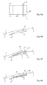
- FIGS. 4A, 4B, 4C, 4D illustrate a first mode of insertion of a decorative object into the cornea.
- FIG 4A is a front view showing only the housing 10 (cavity 11 and space 13) and the slot 12.
- Figures 4B, 4C and 4D are partial cross-sectional views of the cornea area at different stages of the insertion process. In the example shown, it is assumed a housing of rectangular parallelepiped general shape.
- the Figure 4B illustrates the empty cavity, made with the method described above, before insertion of the object.
- the figure 4C illustrates the establishment of a decorative object 0. It is slid from the slot 12 towards the sliding space 13 by deforming, towards the inside of the eye, the portion 14 of the cornea located above the portion 112 of the housing 11. This portion 14 forms a kind of lip deforming downwards to let the object O while the portion 15 of the cornea above the portion 111 of the housing It deforms outward.
- the object O is inserted until the lip 14 is escaped by engaging in the sliding space 13.
- figure 4D he is brought back under the lip 14 after it has returned to its normal position.
- the object O then occupies the entire housing 11.
- the sliding space 13 and the slot 12 close again.
- the proposed technique requires no suture of the cornea insofar as the slot 12 closes without tension.
- objects can be inserted.
- it may be reflective metal pellets, colored plastic elements of various shapes, minerals (precious or semi-precious stones), thin objects in the form of plastic or metal films, filaments, etc.
- it may be required to coat it with a biocompatible material prior to insertion, for example plexiglass.
- the same cavity has several slots.
- the object or objects form a marking.
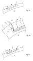
- FIGS. 5A, 5B and 5C illustrate another embodiment in which the housing 11 'is used to receive a gel G, not likely to diffuse into the cornea, constituting the decorative object inserted or marking.
- the housing 11 ' is, for example, generally tubular in shape approximately parallel to the surface of the cornea.
- the slot 12 is replaced by a communication channel 12 'allowing the introduction of a cannula 25 for injection of the gel G.
- a lip 16 forming a shutter valve of the channel 12' is defined by the laser during the formation of the cavity. This lip 16 is deformed ( Figure 5B ) during the introduction of the cannula to resume its original form once the gel introduced and the cannula out ( Figure 5C ), thus closing the channel 12 'to retain the gel G inside the housing 11'.
- a sliding space is not necessary.
- a secondary channel 17, slot or communication space of other shape between the housing 11 'and the outside of the eye is preferably provided and is arranged near the other end of the housing 11' relative to at the channel 12 '. This vent channel makes it possible to evacuate the air contained in the housing 11 'during the introduction of the gel.
- the figure 6 is a partial top view of an eye illustrating other examples of implementation.
- the iris of the iris outside the pupillary area is illustrated by two lines referenced 22 and 23.
- a housing 115 is formed in a radial direction.
- tubular housings 116 of various shapes for drawing are made in the cornea.
- Each housing has its own channel 12 'and vent 17.
- the housing can be side by side and / or bunk. For example, they form a marking (inscription having a meaning) of one or more symbols, letters or numbers.
- a housing 117 has a generally planar shape reproducing a tree leaf. The object is then for example a colored film wound on itself which is introduced by the slot 12. Once in the housing 117, the film unfolds and matches the shape of the housing 117.
- the figure 7 is a sectional view illustrating another variant in which a housing 118 has a polygonal shape adapted to receive a cut stone. Again, the dimensions of the housing 118, the slot 12 and the sliding space 13 are adapted to the stone.
- the realization of the cavity 10 and the placement of the material takes place outside the pupillary area and has no healing or restorative, but only for the purpose of adding a ornament to the eye.
- An advantage of the invention is that it preserves the surface appearance of the eye and does not constitute any protuberance with respect to the surface of the cornea. It is compatible with the wearing of contact lenses, in particular corrective lenses.
- Another advantage is that the proposed technique is durable and does not require maintenance, unlike the use of a lens.
- Another advantage is that it allows localized insertions whose angular position can be chosen.
- the modification is reversible.
- the decorative foreign body can be explanted. Just take out the object by its slot of introduction by reusing the space of sliding. Indeed, the intra-corneal cavity 11 and the slot 12, obtained by vaporization of the corneal structure by means of the laser, are not reconstituted.
- the sliding space 13 remains usable to extract the object without trauma. In the case of a gel G or colored liquid, it can be removed by washing the cavity by opening the lip 16.
- the cavity can be filled with a saline or, if the volume of the housing is too large, filled by a transparent implant, for example crosslinked hyaluronic acid, compatible with the nature of the cornea.
- a transparent implant for example crosslinked hyaluronic acid
Landscapes
- Health & Medical Sciences (AREA)
- Engineering & Computer Science (AREA)
- Ophthalmology & Optometry (AREA)
- Biomedical Technology (AREA)
- Vascular Medicine (AREA)
- Public Health (AREA)
- Veterinary Medicine (AREA)
- Heart & Thoracic Surgery (AREA)
- Transplantation (AREA)
- Life Sciences & Earth Sciences (AREA)
- Animal Behavior & Ethology (AREA)
- General Health & Medical Sciences (AREA)
- Cardiology (AREA)
- Oral & Maxillofacial Surgery (AREA)
- Physics & Mathematics (AREA)
- Optics & Photonics (AREA)
- Nuclear Medicine, Radiotherapy & Molecular Imaging (AREA)
- Surgery (AREA)
- Laser Surgery Devices (AREA)
Abstract
L'invention concerne un procédé et système d'insertion d'au moins un objet décoratif ou d'un marquage dans la cornée (1) d'un oeil, comportant les étapes suivantes : réaliser, par laser et hors de l'aire pupillaire, au moins une cavité intra cornéenne (10) débouchant à la surface de l'oeil par au moins une fente (12) ou canal ; et introduire un matériau formant l'objet décoratif ou le marquage dans la cavité par la fente ou canal.
Description
- La présente invention concerne de façon générale les accessoires d'ornements utilisés par l'être humain afin de modifier son apparence dans un but esthétique ou de marquage.
- Les techniques utilisées pour associer au corps des objets décoratifs, par exemple des bijoux, incluent des techniques invasives pour fixer ces objets de façon durable (réversible ou non). Par exemple, la technique dite de piercing consiste à fixer, par l'intermédiaire d'un canal dans l'épiderme, un objet décoratif (anneau, clou, etc.). Une autre technique connue consiste à apporter des déformations à la surface du corps par l'insertion de corps étrangers sous la peau. De même, les techniques de tatouage consistent à insérer des encres sous la peau pour donner des motifs visibles.
- Un organe qui se remarque particulièrement d'un point de vue esthétique est l'oeil, ne serait-ce que par les différences de couleur qu'il procure entre les individus. Modifier l'esthétique de l'oeil s'effectue aujourd'hui au moyen de lentilles cornéennes qui peuvent n'avoir aucune fonction de correction de la vision. Ces lentilles comportent, en regard de l'iris, une zone colorée avec ou sans motif afin de modifier l'aspect de l'oeil. De telles lentilles cornéennes sont des accessoires d'ornements non durables qui requièrent un entretien régulier (nettoyage, hydratation, etc.). De plus, les lentilles permettent difficilement de présenter des motifs ayant une orientation angulaire déterminée.
- Il serait souhaitable de pouvoir associer à l'oeil un ornement, de façon plus durable qu'une lentille.
- Il serait également souhaitable de pouvoir sélectionner une orientation angulaire de l'ornement.
- Une difficulté réside dans le fait que la fonction de l'oeil qui constitue un organe particulièrement sensible du corps humain ne doit pas être perturbée.
- Une autre difficulté est que l'oeil est un organe mobile qui se trouve périodiquement recouvert par les paupières, ce qui requiert de préserver une surface externe régulière.
- L'invention vise à orner l'oeil d'un objet décoratif ou d'un marquage.
- Un autre objet vise à préserver la surface externe régulière de l'oeil.
- Un autre objet vise à éviter de recouvrir cette surface externe par un corps étranger de type lentille.
- Un autre objet vise une solution réversible.
- Pour atteindre tout ou partie de ces objets ainsi que d'autres, il est prévu un procédé d'insertion d'au moins un objet décoratif ou d'un marquage dans la cornée d'un oeil, comportant les étapes suivante :
- réaliser, par laser et hors de l'aire pupillaire, au moins une cavité intra cornéenne débouchant à la surface de l'oeil par au moins une fente ou canal ; et
- introduire un matériau formant l'objet décoratif ou le marquage dans la cavité par la fente ou canal.
- Selon un mode de mise en oeuvre de la présente invention, la cavité définit :
- au moins un logement de réception du matériau de direction principale approximativement parallèle à la surface de la cornée, le logement débouchant par une fente dont l'aplomb sépare le logement en deux parties dans sa direction principale ; et
- un espace de déformation, communiquant avec l'extrémité d'une desdites parties du logement, d'épaisseur inférieure à celle du logement et de longueur, dans ladite direction principale, au moins égale à celle de l'autre partie.
- Selon un mode de mise en oeuvre de la présente invention, l'objet est introduit par la fente en direction de l'espace de déformation jusqu'à ce qu'il soit entièrement dans la cavité, puis ramené en direction de la deuxième partie du logement jusqu'à libérer l'espace de déformation.
- Selon un mode de mise en oeuvre de la présente invention, l'objet est enrobé d'un matériau biocompatible avec la nature de la cornée préalablement à son insertion.
- Selon un mode de mise en oeuvre de la présente invention, le matériau est une pierre.
- Selon un mode de mise en oeuvre de la présente invention, le matériau est métallique.
- Selon un mode de mise en oeuvre de la présente invention, le matériau est une matière plastique.
- Selon un mode de mise en oeuvre de la présente invention, la cavité définit :
- au moins un logement de réception du matériau de direction principale approximativement parallèle à la surface de la cornée, le logement débouchant par au moins un premier canal d'introduction d'un outil de dépôt du matériau à l'intérieur du logement, le canal étant obturable par une lèvre déformable, ménagée dans l'épaisseur de la cornée ; et
- au moins un canal d'évent établissant une deuxième communication entre le logement et la surface de l'oeil.
- Selon un mode de mise en oeuvre de la présente invention, le matériau est un gel ou liquide coloré, non susceptible de diffuser dans la cornée.
- Il est également prévu un système d'insertion d'un objet décoratif ou d'un marquage dans la cornée d'un oeil, hors de l'aire pupillaire, comportant :
- un laser programmé pour la réalisation d'une cavité ; et
- un matériau formant un objet décoratif ou un marquage à loger dans la cavité.
- Ces objets, caractéristiques et avantages, ainsi que d'autres seront exposés en détail dans la description suivante de modes de mise en oeuvre et de réalisation particuliers faite à titre non-limitatif en relation avec les figures jointes parmi lesquelles :
- la
figure 1 est une coupe transversale schématique d'un oeil ; - la
figure 2 représente un détail de la coupe de lafigure 1 illustrant un mode de mise en oeuvre de l'invention ; - la
figure 3 est une vue de face correspondant à lafigure 2 ; - les
figures 4A, 4B, 4C et 4D illustrent, respectivement par une vue de dessus et par des coupes transversales partielles, un mode de mise en oeuvre de l'invention ; - les
figures 5A, 5B et 5C sont des coupes transversales partielles illustrant un autre mode de mise en oeuvre ; - la
figure 6 est une vue partielle illustrant différentes variantes de réalisation de cavités d'inclusion d'objets décoratifs ; et - la
figure 7 illustre une autre variante d'une cavité. - De mêmes éléments ont été désignés par de mêmes références aux différentes figures.
- La
figure 1 est une coupe transversale schématique et partielle d'un oeil faisant apparaître, à l'arrière de la cornée 1, l'iris 2 et le cristallin 3. La périphérie externe de l'iris 2 rejoint l'uvée 5 (le corps ciliaire) auquel est lié le cristallin 3. L'ensemble baigne dans l'humeur aqueuse 6 (entre la cornée et le cristallin) ou vitrée 7 (derrière le cristallin). En périphérie de la cornée, se trouve la sclère 8 recouverte à l'extérieur par la conjonctive 9 qui forme le blanc de l'oeil et qui s'arrête en périphérie de la cornée. Dans la représentation de lafigure 1 apparaissent des canaux lacrymaux 81 entre la sclère et la cornée. La pupille 21, formée par l'ouverture centrale de l'iris 2 au diamètre variable contrôle le flux de lumière pénétrant dans l'oeil en traversant la cornée. - La cornée est constituée de différentes couches. A l'extérieur se trouve l'épithélium cornéen 1a qui présente une épaisseur d'environ 50 µm représentant approximativement un dixième de l'épaisseur totale de la cornée. En dessous se trouve la membrane de Bowman 1b qui sépare l'épithélium cornéen du stroma cornéen 1c. Le stroma 1c constitue la couche principale de la cornée. Son épaisseur est généralement comprise entre 400 et 600 µm. Côté intérieur de l'oeil, l'endothélium cornéen 1d donne à la cornée sa transparence.
- Selon un mode de mise en oeuvre, l'invention prévoit de ménager une cavité dans la cornée afin d'y inclure un objet décoratif ou un marquage. Cette cavité est créée principalement dans le stroma cornéen et hors de l'aire pupillaire (hors du champ de vision), c'est-à-dire à l'aplomb d'une partie de l'iris qui subsiste quelle que soit la dilatation de la pupille.
- La cavité est obtenue au moyen d'un laser du type de ceux utilisés habituellement à des fins curatives, par exemple des interventions de chirurgie pour inclure des "intacts" dans la cornée afin de modifier sa courbure et corriger ainsi des astigmatismes asymétriques (par exemple, le kératocône). Les "intacts" sont des segments arciformes de plexiglas qui sont glissés dans des espaces créés dans la cornée afin d'en modifier la courbure. L'invention prévoit d'utiliser ce type de laser hors du champ de vision afin de ne pas affecter la fonctionnalité de l'oeil. Un exemple de laser utilisable est un laser fournissant des impulsions d'une durée de l'ordre de la femtoseconde. Un tel outil est susceptible de réaliser des incisions dans la cornée avec une précision meilleure que 10 µm. Par exemple, des lasers connus sous la dénomination commerciale FEMTEC conviennent.
- Par rapport à d'autres lasers, les lasers femtoseconde permettent de réaliser des cavités intra cornéennes sans qu'il soit nécessaire de découper une partie externe pour rendre accessible la partie à creuser. La précision d'un laser femtoseconde permet de ne vaporiser que des zones enterrées dans la cornée sans détruire les zones superficielles. Un tel laser peut être programmé pour réaliser la cavité en mode automatique.
- La cavité créée au moyen du laser comporte au moins un espace ou logement destiné à recevoir au moins un matériau d'ornement formant un objet décoratif ou un marquage. Les formes et dimensions de ce logement sont donc adaptées aux dimensions de l'objet ou du marquage. Une fente ou canal reliant le logement à l'extérieur de l'oeil sert à introduire le matériau. La cavité est principalement réalisée dans le stroma cornéen dont l'épaisseur est compatible avec différentes tailles d'objets à implanter. En pratique, l'épaisseur maximale du logement ne devra pas dépasser 200 µm afin de laisser subsister au moins une épaisseur de l'ordre de 250 µm de stroma cornéen sous le logement. L'épaisseur de stroma au dessus du logement est par exemple d'au moins 100 µm.
- Les
figures 2 et 3 sont respectivement des vues en coupe et de face d'une partie d'un oeil dans une zone ou a été réalisée une cavité intra cornéenne 10. - La cavité 10 comporte un espace ou logement 11 de réception d'un objet qui communique avec l'extérieur par une fente 12, de préférence rectiligne, servant à introduire l'objet. Cette fente 12 n'est pas réalisée à une extrémité du logement mais de façon que son aplomb sépare le logement 11 en deux parties 111 et 112. La direction approximativement perpendiculaire au plan de la fente 12 définit la direction principale (arbitrairement longitudinale) de la cavité 10. La longueur de la fente 12 est de préférence supérieure à la largeur de la cavité dans une proportion fonction de l'épaisseur de l'objet, de façon à autoriser une déformation non traumatisante permettant d'introduire l'objet. La cavité est complétée par un espace 13 de glissement ou de déformation servant lors de la mise en place de l'objet. Cet espace 13 communique avec la première partie 111 du logement, du côté de son extrémité opposée à la fente. L'espace 13 est d'épaisseur inférieure à celle du logement 11 et sa longueur, dans la direction principale de la cavité 10, correspond approximativement à celle de la deuxième partie 112 du logement.
- Dans l'exemple de la
figure 3 , le logement 11 a une forme générale circulaire, par exemple celle d'un disque. Un laser femtoseconde permet toutefois de créer une cavité intra cornéenne de toute forme souhaitée (par exemple, sphérique, ovoïde, parallélépipédique, polygonale, en forme de disque, tubulaire, etc.). - Les
figures 4A, 4B, 4C, 4D illustrent un premier mode d'insertion d'un objet décoratif dans la cornée. - La
figure 4A est une vue de face représentant uniquement le logement 10 (cavité 11 et espace 13) et la fente 12. Lesfigures 4B, 4C et 4D sont des vues partielles en coupe transversale de la zone de la cornée à différentes étapes du procédé d'insertion. Dans l'exemple représenté, on suppose un logement de forme générale parallélépipédique rectangle. - La
figure 4B illustre la cavité vide, réalisée avec le procédé décrit ci-dessus, avant insertion de l'objet. - La
figure 4C illustre la mise en place d'un objet décoratif 0. Celui-ci est glissé à partir de la fente 12 en direction de l'espace de glissement 13 en déformant, vers l'intérieur de l'oeil, la partie 14 de la cornée située au-dessus de la partie 112 du logement 11. Cette partie 14 forme en quelque sorte une lèvre se déformant vers le bas pour laisser passer l'objet O alors que la partie 15 de la cornée au-dessus de la partie 111 du logement 11 se déforme vers l'extérieur. L'objet O est inséré jusqu'à échapper la lèvre 14 en s'engageant dans l'espace de glissement 13. Puis (figure 4D ), il est ramené sous la lèvre 14 après que celle-ci ait repris sa position normale. L'objet O occupe alors l'intégralité du logement 11. L'espace de glissement 13 ainsi que la fente 12 se referment. - La technique proposée ne requiert aucune suture de la cornée dans la mesure où la fente 12 se referme sans tension.
- Différents types d'objets peuvent être insérés. Par exemple, il pourra s'agir de pastilles métalliques réfléchissantes, d'éléments plastiques colorés de formes diverses, de minéraux (pierres précieuses ou semi-précieuses), d'objets minces sous forme de films plastiques ou métalliques, de filaments, etc. Selon la nature de l'objet, il pourra être requis de l'enrober d'un matériau biocompatible préalablement à son insertion, par exemple du plexiglas.
- En variante, plusieurs objets peuvent être introduits à partir d'une même fente dans une même cavité comportant plusieurs logements et espaces de glissement (par exemple, en étoile).
- Selon une autre variante, une même cavité comporte plusieurs fentes.
- Selon une autre variante, le ou les objets forment un marquage.
- Les
figures 5A, 5B et 5C illustrent un autre mode de mise en oeuvre dans lequel le logement 11' est utilisé pour recevoir un gel G, non susceptible de diffuser dans la cornée, constituant l'objet décoratif inséré ou un marquage. Le logement 11' est, par exemple, de forme générale tubulaire approximativement parallèle à la surface de la cornée. La fente 12 est remplacée par un canal de communication 12' permettant l'introduction d'une canule 25 d'injection du gel G. Une lèvre 16 formant clapet d'obturation du canal 12' est définie par le laser lors de la formation de la cavité. Cette lèvre 16 se déforme (figure 5B ) lors de l'introduction de la canule pour reprendre sa forme d'origine une fois le gel introduit et la canule sortie (figure 5C ), obturant ainsi le canal 12' pour retenir le gel G à l'intérieur du logement 11'. - Par rapport au mode de réalisation précédent, un espace de glissement n'est pas nécessaire. Par contre, un canal secondaire 17, fente ou espace de communication d'autre forme entre le logement 11' et l'extérieur de l'oeil est de préférence prévu et est disposé à proximité de l'autre extrémité du logement 11' par rapport au canal 12'. Ce canal formant évent permet d'évacuer l'air contenu dans le logement 11' lors de l'introduction du gel.
- La
figure 6 est une vue de dessus partielle d'un oeil illustrant d'autres exemples de mise en oeuvre. L'aplomb de l'iris hors de l'aire pupillaire est illustré par deux traits référencés 22 et 23. - Selon un premier exemple, un logement 115 est ménagé selon une direction radiale.
- Selon un deuxième exemple, plusieurs logements tubulaires 116 de formes diverses pour effectuer un dessin sont réalisés dans la cornée. Chaque logement possède son propre canal 12' et évent 17. Les logements peuvent être côte à côte et/ou superposés. Par exemple, ils forment un marquage (inscription ayant une signification) d'un ou plusieurs symboles, lettres ou chiffres.
- Selon un troisième exemple, un logement 117 a une forme générale plane reproduisant une feuille d'arbre. L'objet est alors par exemple un film coloré enroulé sur lui-même qui est introduit par la fente 12. Une fois dans le logement 117, le film se déplie et épouse la forme du logement 117.
- La
figure 7 est une vue en coupe illustrant une autre variante selon laquelle un logement 118 a une forme polygonale apte à recevoir une pierre taillée. Là encore, les dimensions du logement 118, de la fente 12 et de l'espace de glissement 13 sont adaptées à la pierre. - Quel que soit le mode de mise en oeuvre, la réalisation de la cavité 10 et la mise en place du matériau s'effectue hors de l'aire pupillaire et n'a aucune vertu curative ou réparatrice, mais uniquement pour objet d'adjoindre un ornement à l'oeil.
- Un avantage de l'invention est qu'elle préserve l'aspect de surface de l'oeil et ne constitue aucune excroissance par rapport à la surface de la cornée. Elle est compatible avec le port de lentilles cornéennes, notamment correctrices.
- Un autre avantage est que la technique proposée est durable et ne nécessite pas d'entretien contrairement à l'utilisation d'une lentille.
- Un autre avantage est qu'elle permet d'effectuer des insertions localisées dont la position angulaire peut être choisie.
- Un autre avantage est que la modification est réversible. Dans le cas d'un objet solide O, le corps étranger décoratif peut être explanté. Il suffit de faire sortir l'objet par sa fente d'introduction en réutilisant l'espace de glissement. En effet, la cavité intra cornéenne 11 et la fente 12, obtenues par vaporisation de la structure cornéenne au moyen du laser, ne se reconstituent pas. L'espace de glissement 13 reste donc utilisable pour extraire l'objet sans traumatisme. Dans le cas d'un gel G ou liquide coloré, celui-ci peut être retiré par lavage de la cavité en ouvrant la lèvre 16.
- Il est donc possible de changer d'objets décoratifs (par exemple en remplaçant une pierre précieuse par une autre) en utilisant le même logement. On peut également redonner à l'oeil son aspect d'origine. Dans ce cas, une fois l'objet explanté, la cavité pourra être remplie d'un sérum physiologique ou, si le volume du logement est trop important, comblée par un implant transparent, par exemple en acide hyaluronique réticulé, compatible avec la nature de la cornée. De tels implants transparents sont déjà utilisés, par exemple, dans la chirurgie du glaucome.
- Des modes de réalisation particuliers de la présente invention ont été décrits. Diverses variantes et modifications apparaîtront à l'homme de l'art. En particulier, le choix du matériau, le nombre de logements réalisés dans la cornée et leurs emplacements dépendent de l'effet souhaité. En outre, l'emploi d'un laser, son paramétrage ou programmation pour la mise en oeuvre de l'invention n'ont pas été détaillés, car ils sont à la portée d'un homme de l'art formé à l'utilisation d'un tel laser. En pratique, un anesthésiant local est utilisé pendant la mise en oeuvre du procédé d'insertion (réalisation de la cavité et mise en place de l'objet). Enfin, les différents modes de réalisation et variantes peuvent être combinés.
Claims (10)
- Procédé d'insertion d'au moins un objet décoratif ou d'un marquage dans la cornée (1) d'un oeil, comportant les étapes suivantes :réaliser, par laser et hors de l'aire pupillaire, au moins une cavité intra cornéenne (10) débouchant à la surface de l'oeil par au moins une fente (12) ou canal (12') ; etintroduire un matériau formant l'objet décoratif (O, G) ou le marquage dans la cavité par la fente ou canal.
- Procédé selon la revendication 1, dans lequel la cavité (10) définit :au moins un logement (11, 115, 117, 118) de réception du matériau (O) de direction principale approximativement parallèle à la surface de la cornée (1), le logement débouchant par une fente (12) dont l'aplomb sépare le logement en deux parties (111, 112) dans sa direction principale ; etun espace de déformation (13), communiquant avec l'extrémité d'une (111) desdites parties du logement, d'épaisseur inférieure à celle du logement et de longueur, dans ladite direction principale, au moins égale à celle de l'autre partie (112).
- Procédé selon la revendication 2, dans lequel l'objet (O) est introduit par la fente (12) en direction de l'espace de déformation (13) jusqu'à ce qu'il soit entièrement dans la cavité (11, 115, 117, 118), puis ramené en direction de la deuxième partie (112) du logement jusqu'à libérer l'espace de déformation.
- Procédé selon la revendication 2 ou 3, dans lequel l'objet (O) est enrobé d'un matériau biocompatible avec la nature de la cornée (1) préalablement à son insertion.
- Procédé selon l'une quelconque des revendications 2 à 4, dans lequel le matériau est une pierre.
- Procédé selon l'une quelconque des revendications 2 à 4, dans lequel le matériau est métallique.
- Procédé selon l'une quelconque des revendications 2 à 4, dans lequel le matériau est une matière plastique.
- Procédé selon la revendication 1, dans lequel la cavité définit :au moins un logement (11', 116) de réception du matériau (G) de direction principale approximativement parallèle à la surface de la cornée, le logement débouchant par au moins un premier canal (12') d'introduction d'un outil (26) de dépôt du matériau à l'intérieur du logement, le canal étant obturable par une lèvre déformable (16), ménagée dans l'épaisseur de la cornée (1) ; etau moins un canal d'évent (17) établissant une deuxième communication entre le logement et la surface de l'oeil.
- Procédé selon la revendication 8, dans lequel le matériau est un gel (G) ou liquide coloré, non susceptible de diffuser dans la cornée.
- Système d'insertion d'un objet décoratif (O, G) ou d'un marquage dans la cornée (1) d'un oeil, hors de l'aire pupillaire, comportant :un laser programmé pour la réalisation d'une cavité conforme à l'une quelconque des revendications 1 à 9 ; etun matériau (O, G) formant un objet décoratif ou un marquage à loger dans la cavité.
Priority Applications (2)
| Application Number | Priority Date | Filing Date | Title |
|---|---|---|---|
| EP07301689A EP2072024A1 (fr) | 2007-12-18 | 2007-12-18 | Insertion d'un objet décoratif ou d'un marquage dans la cornée d'un oeil |
| PCT/FR2008/052329 WO2009081032A2 (fr) | 2007-12-18 | 2008-12-17 | Insertion d'un objet decoratif ou d'un marquage dans la cornee d'un oeil |
Applications Claiming Priority (1)
| Application Number | Priority Date | Filing Date | Title |
|---|---|---|---|
| EP07301689A EP2072024A1 (fr) | 2007-12-18 | 2007-12-18 | Insertion d'un objet décoratif ou d'un marquage dans la cornée d'un oeil |
Publications (1)
| Publication Number | Publication Date |
|---|---|
| EP2072024A1 true EP2072024A1 (fr) | 2009-06-24 |
Family
ID=39577253
Family Applications (1)
| Application Number | Title | Priority Date | Filing Date |
|---|---|---|---|
| EP07301689A Withdrawn EP2072024A1 (fr) | 2007-12-18 | 2007-12-18 | Insertion d'un objet décoratif ou d'un marquage dans la cornée d'un oeil |
Country Status (2)
| Country | Link |
|---|---|
| EP (1) | EP2072024A1 (fr) |
| WO (1) | WO2009081032A2 (fr) |
Families Citing this family (1)
| Publication number | Priority date | Publication date | Assignee | Title |
|---|---|---|---|---|
| US12364591B2 (en) * | 2019-04-25 | 2025-07-22 | Corneat Vision Ltd | Keratoprosthesis devices and kits and surgical methods of their use |
Citations (3)
| Publication number | Priority date | Publication date | Assignee | Title |
|---|---|---|---|---|
| EP1402851A1 (fr) * | 2002-09-24 | 2004-03-31 | Cesar C. Dr. Carriazo | Implant pour modifier la couleur de l'iris |
| EP1433442A1 (fr) * | 2002-12-24 | 2004-06-30 | Medical Technology Transfer Holding B.V. | Implant oculaire cosmétique |
| US20060118263A1 (en) * | 2004-12-01 | 2006-06-08 | Silvestrini Thomas A | Method of making an ocular implant |
-
2007
- 2007-12-18 EP EP07301689A patent/EP2072024A1/fr not_active Withdrawn
-
2008
- 2008-12-17 WO PCT/FR2008/052329 patent/WO2009081032A2/fr not_active Ceased
Patent Citations (3)
| Publication number | Priority date | Publication date | Assignee | Title |
|---|---|---|---|---|
| EP1402851A1 (fr) * | 2002-09-24 | 2004-03-31 | Cesar C. Dr. Carriazo | Implant pour modifier la couleur de l'iris |
| EP1433442A1 (fr) * | 2002-12-24 | 2004-06-30 | Medical Technology Transfer Holding B.V. | Implant oculaire cosmétique |
| US20060118263A1 (en) * | 2004-12-01 | 2006-06-08 | Silvestrini Thomas A | Method of making an ocular implant |
Also Published As
| Publication number | Publication date |
|---|---|
| WO2009081032A2 (fr) | 2009-07-02 |
| WO2009081032A3 (fr) | 2009-12-03 |
Similar Documents
| Publication | Publication Date | Title |
|---|---|---|
| EP1313416B1 (fr) | Drain a glaucome | |
| EP0877584B1 (fr) | Dispositif de keratoprothese | |
| JP3061712B2 (ja) | エツジグレアを減らした眼内レンズ | |
| EP1237507B1 (fr) | Implant intraoculaire precristallinien | |
| ES2704162T3 (es) | Córnea artificial deformable reversible | |
| FR2589352A1 (fr) | Lentille intraoculaire comportant des bords non eblouissants et son procede de fabrication | |
| EP0404689B1 (fr) | Lentille pour épikératophakie et kératotome notamment destiné à la réalisation d'une incision de réception d'une telle lentille | |
| BE1022841B1 (fr) | Binocle | |
| EP0488835B1 (fr) | Implant intraoculair multifocale | |
| FR2666735A1 (fr) | Implant intra-oculaire a cavite interne. | |
| FR2465473A1 (fr) | Cristallin artificiel et procede d'implantation de celui-ci | |
| US20060118263A1 (en) | Method of making an ocular implant | |
| EP3187158A1 (fr) | Dispositif placé sous la paupière | |
| FR2987776A1 (fr) | Procede de realisation d'un ecran de vision a insert surmoule par injection | |
| EP0469993A1 (fr) | Cornée artificielle | |
| FR2862524A1 (fr) | Implant oculaire pour la correction des defauts de la vision | |
| EP3277237B1 (fr) | Implant ophtalmologique d'interposition | |
| WO2009081032A2 (fr) | Insertion d'un objet decoratif ou d'un marquage dans la cornee d'un oeil | |
| WO1995015733A1 (fr) | Implant intra-oculaire | |
| EP0276331A1 (fr) | Implant intraoculaire de correction de l'aphakie | |
| WO2007051951A2 (fr) | Microtome laser femtoseconde pour decoupe par faisceau laser d'une tranche de matiere, notamment dans une cornee | |
| FR3119763A1 (fr) | Implant ophtalmologique d’interposition a excroissance de contact | |
| FR2611487A1 (fr) | Dispositif chirurgical ophtalmologique compose d'un element porteur et d'un element porte qui est une lentille intra-oculaire | |
| WO2020002849A1 (fr) | Procédé de réalisation d'un bijou comportant un végétal naturel et bijou ainsi obtenu | |
| JP2013132503A (ja) | 眼内レンズ |
Legal Events
| Date | Code | Title | Description |
|---|---|---|---|
| PUAI | Public reference made under article 153(3) epc to a published international application that has entered the european phase |
Free format text: ORIGINAL CODE: 0009012 |
|
| AK | Designated contracting states |
Kind code of ref document: A1 Designated state(s): AT BE BG CH CY CZ DE DK EE ES FI FR GB GR HU IE IS IT LI LT LU LV MC MT NL PL PT RO SE SI SK TR |
|
| AX | Request for extension of the european patent |
Extension state: AL BA HR MK RS |
|
| AKX | Designation fees paid | ||
| REG | Reference to a national code |
Ref country code: DE Ref legal event code: 8566 |
|
| STAA | Information on the status of an ep patent application or granted ep patent |
Free format text: STATUS: THE APPLICATION IS DEEMED TO BE WITHDRAWN |
|
| 18D | Application deemed to be withdrawn |
Effective date: 20091229 |