EP2072026A1 - Modulare Mittelohr-Totalprothese - Google Patents
Modulare Mittelohr-Totalprothese Download PDFInfo
- Publication number
- EP2072026A1 EP2072026A1 EP08018714A EP08018714A EP2072026A1 EP 2072026 A1 EP2072026 A1 EP 2072026A1 EP 08018714 A EP08018714 A EP 08018714A EP 08018714 A EP08018714 A EP 08018714A EP 2072026 A1 EP2072026 A1 EP 2072026A1
- Authority
- EP
- European Patent Office
- Prior art keywords
- prosthesis
- middle ear
- receiving part
- shoe
- ear prosthesis
- Prior art date
- Legal status (The legal status is an assumption and is not a legal conclusion. Google has not performed a legal analysis and makes no representation as to the accuracy of the status listed.)
- Granted
Links
Images


Classifications
-
- A—HUMAN NECESSITIES
- A61—MEDICAL OR VETERINARY SCIENCE; HYGIENE
- A61F—FILTERS IMPLANTABLE INTO BLOOD VESSELS; PROSTHESES; DEVICES PROVIDING PATENCY TO, OR PREVENTING COLLAPSING OF, TUBULAR STRUCTURES OF THE BODY, e.g. STENTS; ORTHOPAEDIC, NURSING OR CONTRACEPTIVE DEVICES; FOMENTATION; TREATMENT OR PROTECTION OF EYES OR EARS; BANDAGES, DRESSINGS OR ABSORBENT PADS; FIRST-AID KITS
- A61F2/00—Filters implantable into blood vessels; Prostheses, i.e. artificial substitutes or replacements for parts of the body; Appliances for connecting them with the body; Devices providing patency to, or preventing collapsing of, tubular structures of the body, e.g. stents
- A61F2/02—Prostheses implantable into the body
- A61F2/18—Internal ear or nose parts, e.g. ear-drums
-
- A—HUMAN NECESSITIES
- A61—MEDICAL OR VETERINARY SCIENCE; HYGIENE
- A61F—FILTERS IMPLANTABLE INTO BLOOD VESSELS; PROSTHESES; DEVICES PROVIDING PATENCY TO, OR PREVENTING COLLAPSING OF, TUBULAR STRUCTURES OF THE BODY, e.g. STENTS; ORTHOPAEDIC, NURSING OR CONTRACEPTIVE DEVICES; FOMENTATION; TREATMENT OR PROTECTION OF EYES OR EARS; BANDAGES, DRESSINGS OR ABSORBENT PADS; FIRST-AID KITS
- A61F2/00—Filters implantable into blood vessels; Prostheses, i.e. artificial substitutes or replacements for parts of the body; Appliances for connecting them with the body; Devices providing patency to, or preventing collapsing of, tubular structures of the body, e.g. stents
- A61F2/02—Prostheses implantable into the body
- A61F2/18—Internal ear or nose parts, e.g. ear-drums
- A61F2002/183—Ear parts
Definitions
- the invention relates to a middle ear prosthesis for the total reconstruction of the human ossicular chain with a shaft-shaped prosthesis body, at one end of a first coupling element is provided, which is designed either as a head plate for mechanically connecting the prosthesis with the eardrum or as a clip for coupling the prosthesis on the hammer handle, and at the other end a second coupling element for mechanical connection of the prosthesis is provided with the Stirrupfußplatte comprising a rigidly connected to the prosthesis body receiving part and a Einschiebeteil which a coaxial to the longitudinal axis of the shaft-shaped prosthesis body in the receiving part insertable plug element and a rigid with the Socket connected shoe, which rests in the implanted state of the prosthesis on the stirrup foot plate.
- the DE 299 04 770 U1 describes middle ear prostheses to be placed between eardrum and stapes footplate.
- the second coupling element for mechanical connection with the stirrup foot plate comprises neither a receiving part nor a push-in part. Rather, a receiving part is provided at the end of a first shaft portion just behind the head plate designed to rest on the eardrum first coupling element. In this receiving part can project from a subsequent second shaft portion plug-in element are introduced to connect the first shaft portion with the second shaft portion, at the opposite other end as a second coupling element, a shoe is integrally attached to the stirrup foot plate.
- a middle ear implant which has a first coupling element to the hammer handle or eardrum on the one hand and as a second coupling element a prosthesis socket with a prosthesis shoe plate for connection to the stirrup foot plate on the other.
- the connecting part between the two coupling elements which is formed in most other middle ear prostheses according to the prior art of a rod-shaped prosthesis stem, is here "conical-micro-slit” executed so that two elongated, partially conical and partially parallel leg away from the first coupling element at a distance from each other in the direction of the second coupling element.
- a ball In the gap between the two legs, a ball is to be inserted, which is rigidly connected to the directed away from the Stirrupfußplatte top of the prosthesis shoe plate.
- a sleeve striped over the conical part of the two legs is intended to compress the two legs and the ball between them. This is intended to achieve an articulated coupling of the prosthesis socket to the connecting part between the two coupling elements.
- first coupling element of a middle ear prosthesis as a clip for coupling to the hammer handle is already known per se, as from the DE 203 10 609 U1 , However, the prostheses described there have no second coupling element designed as a shoe for resting on the stirrup footplate, but either one Piston for direct connection to the inner ear or a second clip.
- the DE 20 2007 012 217 U1 in turn describes middle ear prostheses with a trained as a shoe second coupling element for mechanical connection to the Stirrup foot plate.
- the first coupling element described there may be formed as a clip for attaching the prosthesis to another member of the ossicular chain, but not just on the hammer handle, but for example on the incus process.
- the trained as a shoe second coupling element is not rigidly connected to a plug-in element can be inserted into a receiving part.
- the human middle ear with its ossicles has the task of transmitting the sound waves incident on the eardrum via the external auditory canal to the fluid-filled inner ear.
- the three auditory ossicles are attached to the eardrum hammer (lat. Malleus), the stapes (lat. Stapes), which is connected via its foot plate (lat. Basis stapedis) with the inner ear, and the anvil (Latin incus), the located between the hammer and the stirrup and is hinged thereto.
- the sound signal is not or only partially transferred to the inner ear via the ossicular chain, which leads to deafness.
- Middle ear prostheses are used to improve the sound transmission in different pathological findings. They are used to transmit the sound from the eardrum to the inner ear in the case of completely or partially missing or damaged auditory ossicles of the human middle ear.
- Three types of middle ear prostheses that are commonly used are the stapes prostheses, the partial dentures and the total dentures.
- Partial prostheses are usually with a head plate on the eardrum and connect to the Stirrupkopfchen ago.
- Total Prostheses connect the eardrum to the stirrup footplate.
- the present invention relates exclusively to total dentures.
- a major problem that arises with any reconstruction of the human ossicular chain is the selection of the correct prosthesis length.
- Object of the present invention is in contrast to improve a generic middle ear prosthesis of the type described above with the simplest technical means to the extent that on the one hand a desired, defined length of the prosthesis can be easily made even before their insertion between the two attachment points, this Length is maintained even after the operation is completed, and on the other hand during the operation also on the respectively encountered individual situation of the stapes of the patient (or its remnants) ad hoc responds and an optimal geometric connection of the prosthesis to the Stirrup foot plate can be achieved without that a large variety of differently designed middle ear prostheses must be kept ready.
- this object is achieved in a surprisingly simple and effective manner in that the receiving part at its end facing away from the prosthesis body has a trained as an elongated cavity receiving opening with a cylindrical bore which extends in the axial direction of the prosthesis body and the plug element of the insertion part in fully assembled condition that the clear diameter of the elongated cavity is greater than the maximum transverse extent of the male member transverse to the longitudinal axis of the shaft-shaped prosthesis body, that the elongated cavity in the direction away from the Einschiebeteil is closed on one side and acts as an end stop for the plug element in the mounted state, and that the second coupling element extends in the axial direction of the prosthesis a maximum of one third of the axial length of the prosthesis body.
- an optimal adaptation to the patient can be achieved by simply inserting the plug element of a push-in part of suitable axial length and with geometrically optimal shoe into the oblong cavity of the female part of the prosthesis Implantation situation are produced.
- the individual adaptation does not require a stocking larger assortments of prostheses of different lengths and their availability during each operation. Rather, always a uniform "standard prosthesis with top plate, shaft and receiving part can be used, which - as described above - is optimally individualized by simply inserting a selected from an assortment insert part.
- the second coupling element extends in the axial direction of the prosthesis a maximum of a quarter of the axial length of the prosthesis body, so that in particular a bending of the prosthesis during assembly of the stirrup-side end portion by coupling the insertion part in the receiving part safely avoided.
- the insert part is actively clamped to select discrete relative coaxial positions along an axial distance with the receiving part by an external action on the insertion part and / or on the receiving part, so that almost any desired prosthesis length is below that of the Basic pattern of the prosthesis can individually set maximum length specified individually.
- the jamming by external mechanical force in particular by the action of a crimping tool in the radial direction on the receiving part, can be effected.
- shape memory memory effect
- the use of such materials is known per se in the field of middle ear prostheses, but proves to be particularly effective in the context of the present invention.
- embodiments of the middle ear prosthesis according to the invention are to be preferred, in which the plug element has a continuous cylindrical shape.
- a geometrically and ergonomically favorable embodiment of the middle ear prosthesis according to the invention is characterized in that the plug element has a thickening arranged at its axial end facing the receiving part in the mounted state. This also allows a particularly good coupling of the insertion part in the receiving part to achieve.
- the second coupling element can be easily formed as a ball joint, which has the advantages described below.
- receiving parts which have a cylindrical outer contour in its cross section perpendicular to its longitudinal axis. But not only circular cylindrical are possible Shapes, but also about receiving parts with rectangular cross-section.
- the so-called healing phase begins.
- scars form and these cause unpredictable forces that can cause the prosthesis to move out of its local position.
- a stiff connection between the head plate and the shaft can lead to increased pressure peaks between the edge of the head plate and the eardrum or the gland between the eardrum and the head plate. These may be so high as to result in penetration or extrusion through the eardrum. For this reason, it is very helpful if the prosthesis has a certain post-operative mobility, so that the head plate postoperatively independently can adapt to the position of the eardrum.
- middle ear prostheses are not rigid, but have some flexibility or variability .
- the connecting element between the two fastening elements will be designed as an elongate shaft, as is well known from the prior art.
- the connecting element between the two fastening elements will be designed as an elongate shaft, as is well known from the prior art.
- the connecting element between the two fastening elements will be designed as an elongate shaft, as is well known from the prior art.
- the connecting element between the two fastening elements may be provided in a particularly preferred embodiment of the invention on or in at least one joint, in particular a ball joint.
- the prosthesis body has a plurality of adjacent further rotary elements, preferably an axially extending ball and socket chain.
- the middle ear prosthesis itself or parts thereof may be made of titanium and / or gold and / or tantalum and / or steel and / or an alloy of said metals.
- the material titanium in addition to its strength and excellent sound conduction properties known to also excellent biocompatibility on the human middle ear.
- the prosthesis or parts thereof, in particular one of the fastening elements are made of a memory-memory material or superelastic properties, preferably nitinol or a polymer, what per se, for example, from the WO 02/069850 A1 or the US 6,554,861 B2 is known.
- parts of the middle ear prosthesis according to the invention may be made of a ceramic material.
- embodiments of the invention are also possible in which the entire prosthesis or parts thereof are made of biocompatible plastics, in particular silicone, polytetrafluoroethylene (PTFE) or fiber composite materials, in particular carbon fibers or a thermoplastic are made. With these materials, post-operative rejection reactions can also be prevented in most cases.
- biocompatible plastics in particular silicone, polytetrafluoroethylene (PTFE) or fiber composite materials, in particular carbon fibers or a thermoplastic are made.
- the middle ear of the human body represents a "half-open bearing". Any implantation material that is introduced into the body as part of a reconstruction of the middle ear and its structures , experiences a particular stress that a contaminated and infected environment prevails, which usually attacks the material. Since the goal of implantation of a middle ear prosthesis must always be as long as possible, complication-free residence time of the implant in the middle ear of the patient, a long-lasting material attack can lead to damage to the prosthesis and / or to a local infection. Both consequences are not tolerable.
- the surface of the middle ear prosthesis is completely or at least partially covered with a biologically active coating, in particular a growth-inhibiting and / or a growth-promoting and / or a coated with antibacterial coating.
- a biologically active coating in particular a growth-inhibiting and / or a growth-promoting and / or a coated with antibacterial coating.
- the top plate of the middle ear prosthesis according to the invention should in principle have a growth-promoting coating.
- the middle ear prosthesis according to the invention in which the mass distribution of the individual parts of the prosthesis is calculated as a function of a desired, specifiable frequency response of the sound conduction in the middle ear. Leave it To achieve a tuning of the sound propagation properties by means of an individual designed middle ear prosthesis without great additional technical effort.
- such a tuning effect can be achieved, for example, by attaching at least one additional mass to a part of the auditory ossicular chain or the prosthesis as a function of a desired, predefinable frequency response of the sound conduction in the middle ear.
- the additional mass is attached by means of a clip to a part of the auditory ossicular chain or the prosthesis.
- the additional mass and / or clip may also be coated with a biologically active coating.
- a group of middle ear prostheses of the type described above according to the invention with a Einschiebeteil for insertion into the receiving part, in which the rigidly connected to the plug element shoe, which rests in the implanted state of the prosthesis on the stirrup footplate, falls - or stamp-shaped construction.
- a preferred class of embodiments is characterized in that the in the implanted state of the middle ear prosthesis on the stirrup foot plate fitting end portion of the shoe has a concave towards the male member surface, which ensures the best grip of the prosthesis on the stirrup foot plate in the rule.
- an alternative class of embodiments may be favorable, in which the in the implanted state of the middle ear prosthesis on the Stirrup foot plate fitting end portion of the shoe is flat and ensures a large-scale support.
- Another class of insertion parts for special applications is characterized by the fact that in the implanted state of the middle ear prosthesis on the Stirrup foot plate adjacent end portion of the shoe has a convexly curved in the direction of the plug-in element surface and thus allows a point support.
- the end portion of the shoe has a rotationally ellipsoidal, preferably a spherical shape, which is relatively easy to manufacture.
- the end section of the shoe may have a tip directed against the stirrup footplate in the implanted state of the middle ear prosthesis, allowing the shoe to be bored into the stapes footplate and causing greater adhesion through increased friction.
- the shoe has radially outwardly projecting stabilizer wings on its outer circumference, which, inter alia, enable centering of the arrangement in the oval niche of the stirrup footplate.
- the shoe may have radially inwardly extending recesses on its outer circumference, in which individual bone remnants of the stirrup which are present in the patient intervene and thus enable a firm hold of the prosthesis.
- a geometry of the insertion part may be favorable, in which the shoe has a smaller maximum outer circumference than the plug element. This can be achieved in a simple manner, a reduction of the diameter and thus the effective contact surface of the shoe on the Stirrup foot plate.
- the insert part is stored until it is pushed into the receiving part in a sterile, preferably airtight packaging.
- a middle ear prosthesis in which an assortment of inventively designed insert parts is provided, which are present in different geometric shapes, but designed such that the middle ear prosthesis after insertion of the respective plug element of a push-in part to the end stop in each has the same axial overall length of the elongated cavity of the receiving part.
- an embodiment is advantageous, which is characterized in that the total length of the middle ear prosthesis after insertion of the plug element to the end stop in the elongated cavity of the receiving part between 0.3mm and 0.8mm, preferably 0.5mm.
- the insertion parts are designed so that they have different geometries, but lead in their inserted in the receiving part state to each same axial length of the middle ear prosthesis.
- FIGS. 1a . 1b and 2 schematically illustrated, in detail differently shaped embodiments of the middle ear prosthesis 10 according to the invention ; 20 each have at their one end a first fastening element 11; 21 on.
- the fastening element 11 in the FIGS. 1a and 1b formed as a head plate to rest the prosthesis on the eardrum
- the fastener 21 in Fig. 2 has the shape of a clip for mechanical connection to the hammer handle.
- a second fastening element 12; 22 for mechanically coupling the prosthesis to the stirrup footplate.
- one is the two fastening elements 11; 21 and 12, respectively; 22 sound conducting interconnecting, designed as an elongated shaft prosthesis body 13; 23 arranged.
- the second fastening element 12; 22 each includes a receiving part 14; 24 trained, rigid with the prosthesis body 13; 23 connected first section and a slide-in part 15; 25 formed second portion, which is coaxial with the longitudinal axis of the prosthesis body 13; 23 in a receiving opening of the receiving part 14; 24 insertable plug element 16; 26 as well a rigid with the plug-in element 16; 26 connected shoe 18; 28 , which in the implanted state of the prosthesis 10; 20 rests on the stirrup foot plate
- the clear diameter of the elongated cavity 17 is greater than the maximum transverse extent of the plug-in element 16; 26 transversely to the longitudinal axis of the shaft-shaped prosthesis body 13; 23, the elongated cavity 17 is in the direction of the insertion part 15; 25 way closed on one side and acts in the mounted state as an end stop for the plug-in element 16; 26.
- the second coupling element 12; 22 extends in the axial direction of the prosthesis a maximum of one third, preferably not more than a quarter of the axial length of the prosthesis body 13; 23rd
- a ball joint 29 is integrated in order to achieve a certain postoperative flexibility of the middle ear prosthesis 20 between its connection points.
- the mass distribution of the individual parts of the middle ear prosthesis 10 according to the invention; 20 may be calculated in response to a desired, predetermined frequency response of the sound conduction in the middle ear such that an individual tuning of the sound conduction properties is made possible.
- a biologically active coating in particular a growth-inhibiting and / or growth-promoting and / or antibacterial coating of the middle ear prosthesis 10; 20 may be provided.
- FIGS. 3a to 3f has the insertion part 35a; 35b; 35c; 35d; 35e; 35f each have different geometrical configurations which, for different patient-specific situations in the area of the stirrup footplate, allow ad hoc optimal adaptation of the middle ear prosthesis, as explained above:
- the insertion part 35a has a spherically thickened plug element 36a and a concavely arched shoe 38a .
- the insertion part 35b comprises a cylindrical plug element 36b as well as a convexly outwardly curved shoe 38b in a spherical shape .
- the insertion parts 35c; 35d each have an iw cylindrical plug element 36c; 36d and a flat shoe 38c; 38d , which on its end portion each directed in the implanted state of the middle ear prosthesis against the Stirrupfußplatte tip 39c; 39d carries, wherein the end portion may be flat, concave or convex curved design.
- the top 39c in Fig. 3c is additionally surrounded in its neck region at the end portion of the shoe 38c with an annular bead, which prevents large-scale support of the end portion on the stirrup foot plate.
- the shoe 38e has a smaller maximum outer circumference than the plug element 36e .
- the insertion part 35f comprises a hollow-cylindrical plug-in element 36f and a shoe 38f which has recesses running radially inwards on its outer circumference.
Landscapes
- Health & Medical Sciences (AREA)
- Otolaryngology (AREA)
- Pulmonology (AREA)
- Cardiology (AREA)
- Oral & Maxillofacial Surgery (AREA)
- Transplantation (AREA)
- Engineering & Computer Science (AREA)
- Biomedical Technology (AREA)
- Heart & Thoracic Surgery (AREA)
- Vascular Medicine (AREA)
- Life Sciences & Earth Sciences (AREA)
- Animal Behavior & Ethology (AREA)
- General Health & Medical Sciences (AREA)
- Public Health (AREA)
- Veterinary Medicine (AREA)
- Prostheses (AREA)
- Materials For Medical Uses (AREA)
Abstract
Description
- Die Erfindung betrifft eine Mittelohrprothese zur totalen Rekonstruktion der menschlichen Gehörknöchelchenkette mit einem schaftförmigen Prothesenkörper, an dessen einem Ende ein erstes Koppelelement vorgesehen ist, das entweder als Kopfplatte zur mechanischen Verbindung der Prothese mit dem Trommelfell oder als Clip zum Ankoppeln der Prothese am Hammergriff ausgeführt ist, und an dessen anderem Ende ein zweites Koppelelement zur mechanischen Verbindung der Prothese mit der Steigbügelfußplatte vorgesehen ist, das ein starr mit dem Prothesenkörper verbundenes Aufnahmeteil sowie ein Einschiebeteil umfasst, welches ein koaxial zur Längsachse des schaftförmigen Prothesenkörpers in das Aufnahmeteil einschiebbares Steckelement sowie einen starr mit dem Steckelement verbundenen Schuh aufweist, der im implantierten Zustand der Prothese auf der Steigbügelfußplatte anliegt.
- In der Ausgestaltung mit einer Kopfplatte zur Anlage am Trommelfell ist eine derartige Totalprothese bekannt aus der
EP 1 181 907 B1 . - Auch die
DE 299 04 770 U1 beschreibt Mittelohrprothesen, die zwischen Trommelfell und Steigbügelfußplatte angebracht werden sollen. Jedoch umfasst bei diesen bekannten Prothesen das zweite Koppelelement zur mechanischen Verbindung mit der Steigbügelfußplatte weder ein Aufnahmeteil noch ein Einschiebeteil. Vielmehr ist ein Aufnahmeteil am Ende eines ersten Schaftabschnitts kurz hinter dem als Kopfplatte zur Anlage am Trommelfell ausgebildeten ersten Koppelelement vorgesehen. In dieses Aufnahmeteil kann ein aus einem daran anschließenden zweiten Schaftabschnitt ragendes Steckelement eingeführt werden, um den ersten Schaftabschnitt mit dem zweiten Schaftabschnitt zu verbinden, an dessen entgegengesetztem anderen Ende als zweites Koppelelement ein Schuh zur Anlage an der Steigbügelfußplatte einstückig angebracht ist. - In der
DE 20 2004 012 148 U1 ist ein Mittelohrimplantat beschrieben, welches ein erstes Koppelelement zum Hammergriff oder Trommelfell einerseits und als zweites Koppelelement einen Prothesensockel mit einer Prothesenschuhplatte zur Verbindung mit der Steigbügelfußplatte andererseits aufweist. Das Verbindungsteil zwischen den beiden Koppelelementen, das bei den meisten anderen Mittelohrprothesen nach den Stand der Technik von einem Stabförmigen Prothesenschaft gebildet wird, soll hier "konisch-mikrogeschlitzt" ausgeführt sein, so dass zwei längliche, abschnittsweise konische und abschnittsweise parallele Schenkel vom ersten Koppelelement weg mit Abstand voneinander in Richtung auf das zweite Koppelelement verlaufen. In den Spalt zwischen den beiden Schenkeln soll eine Kugel eingesteckt werden, die starr mit der von der Steigbügelfußplatte weg gerichteten Oberseite der Prothesenschuhplatte verbunden ist. Eine über den konischen Teil der beiden Schenkel gestreifte Hülse soll die beiden Schenkel sowie die Kugel dazwischen zusammenpressen. Damit soll eine gelenkige Ankopplung des Prothesensockels an das Verbindungsteil zwischen den beiden Koppelelementen erreicht werden. - Eine Ausbildung des ersten Koppelelements einer Mittelohrprothese als Clip zum Ankoppeln am Hammergriff ist per se bereits bekannt, etwa aus der
DE 203 10 609 U1 . Die dort beschriebenen Prothesen weisen allerdings kein als Schuh zur Auflage auf der Steigbügelfußplatte ausgebildetes zweites Koppelelement auf, sondern entweder einen Kolben zur direkten Verbindung mit dem Innenohr oder einen zweiten Clip. - Die
DE 20 2007 012 217 U1 wiederum beschreibt Mittelohrprothesen mit einem als Schuh ausgebildeten zweiten Koppelelement zur mechanischen Verbindung mit der Steigbügelfußplatte. Auch kann das dort beschriebene erste Koppelelement als Clip zur Befestigung der Prothese an einem anderen Glied der Gehörknöchelchenkette ausgebildet sein, jedoch gerade nicht am Hammergriff, sondern beispielsweise am Ambossfortsatz. Außerdem ist das als Schuh ausgebildete zweite Koppelelement nicht starr mit einem in ein Aufnahmeteil einschiebbaren Steckelement verbunden. - Das menschliche Mittelohr mit seinen Gehörknöchelchen hat die Aufgabe, die über den äußeren Gehörgang auf das Trommelfell auftreffenden Schallwellen auf das mit Flüssigkeit gefüllte Innenohr zu übertragen. Die drei Gehörknöchelchen sind der am Trommelfell befestigte Hammer (lat. malleus), der Steigbügel (lat. stapes), der über seine Fußplatte (lat. basis stapedis) mit dem Innenohr verbunden ist, und der Amboss (lat. incus), der sich zwischen dem Hammer und dem Steigbügel befindet und mit diesen gelenkig verbunden ist. Beispielsweise die Otosklerose ist eine Erkrankung des menschlichen Felsenbeins (= Knochen, in dem das gesamte Ohr sitzt), bei der es durch entzündungsähnliche Knochenumbauprozesse zu einer Fixierung des normalerweise locker schwingenden Steigbügels kommen kann. Dadurch wird das Schallsignal nicht oder nur unvollkommen über die Gehörknöchelchenkette auf das Innenohr übertragen, was zur Schwerhörigkeit führt.
- Mittelohrprothesen dienen der Verbesserung der Schall-übertragung bei unterschiedlichen pathologischen Befunden. Sie werden verwendet, um bei ganz oder teilweise fehlenden oder geschädigten Gehörknöchelchen des menschlichen Mittelohrs den Schall vom Trommelfell zum Innenohr zu übertragen. Drei besonders häufig verwendete Arten von Mittelohrprothesen sind die Steigbügel-Prothesen, die Partial-Prothesen und die Total-Prothesen. Steigbügel-Prothesen (=Stapes-Prothesen) werden am Amboss fixiert und ragen über einen Stempel (=Piston) ins Innenohr. Partial-Prothesen liegen meist mit einer Kopfplatte am Trommelfell an und stellen eine Verbindung zum Steigbügelköpfchen her. Total-Prothesen verbinden das Trommelfell mit der SteigbügelFußplatte. Die vorliegende Erfindung betrifft ausschließlich Total-Prothesen.
- Ein Hauptproblem, das bei jeder Rekonstruktion der menschlichen Gehörknöchelchenkette auftaucht, ist die Auswahl der richtigen Prothesenlänge. Anatomisch bedingt, variieren die jeweils erforderlichen Längen in einem Spektrum von mehreren Millimetern. Daher muss beim operativen Einsetzen einer Mittelohrprothese entweder eine ausreichend große Auswahl von Prothesen unterschiedlicher axialer Länge bereitgehalten werden oder die verwendeten Gehörknöchelchenprothesen müssen während der Operation ausgehend von einer maximalen oder minimalen Ausgangslänge auf die erforderliche axiale Endlänge gebracht werden können.
- Ein weiteres gravierendes Problem insbesondere der Total-Prothesen liegt darin, dass Ossikel-Rekonstruktionen bei fehlendem Amboss und gleichzeitig fehlendem Steigbügeloberbau per se immer das hohe Risiko einer Instabilität oder Dislokation der Prothese in sich tragen. Hinzu kommen unterschiedliche, patientenindividuelle anatomische Gegebenheiten, die präoperativ in der Regel nicht eindeutig feststellbar sind, und die nicht nur die erforderliche axiale Länge der Prothese betreffen, sondern auch zahlreiche andere geometrische Parameter. Diese machen es für den Operateur schwer und aufwändig, die jeweils optimale Verbindung zwischen Prothese und Steigbügelfußplatte dauerhaft zu erzielen.
- Aufgabe der vorliegenden Erfindung ist es demgegenüber, eine gattungsgemäße Mittelohrprothese der eingangs beschriebenen Art mit möglichst einfachen technischen Mitteln dahin gehend zu verbessern, dass einerseits eine gewünschte, definierte Länge der Prothese auch schon vor ihrem Einsetzen zwischen den beiden Befestigungspunkten leicht hergestellt werden kann, wobei diese Länge auch nach Abschluss der Operation fix beibehalten wird, und dass andererseits während der Operation auch auf die jeweils vorgefundene individuelle Situation des Steigbügels des Patienten (oder dessen Reste) ad hoc reagiert und eine optimale geometrische Anbindung der Prothese an die Steigbügelfußplatte erreicht werden kann, ohne dass eine große Vielzahl verschieden ausgestalteter Mittelohrprothesen bereitgehalten werden muss.
- Erfindungsgemäß wird diese Aufgabe auf ebenso überraschend einfache wie wirkungsvolle Art und Weise dadurch gelöst, dass das Aufnahmeteil an seinem dem Prothesenkörper abgewandten Ende eine als länglicher Hohlraum ausgebildete Aufnahmeöffnung mit zylindrischer Bohrung aufweist, die sich in axialer Richtung des Prothesenkörpers erstreckt und das Steckelement des Einschiebeteils im montierten Zustand vollumfänglich umgibt, dass der lichte Durchmesser des länglichen Hohlraums größer ist als die maximale Querausdehnung des Steckelements quer zur Längsachse des schaftförmigen Prothesenkörpers, dass der längliche Hohlraum in Richtung vom Einschiebeteil weg einseitig geschlossen ist und im montierten Zustand als Endanschlag für das Steckelement wirkt, und dass das zweite Koppelelement sich in axialer Richtung der Prothese maximal ein Drittel der axialen Länge des Prothesenkörpers erstreckt.
- Auf diese Weise kann je nach der - erst während der Operation vorgefundenen - individuellen Situation der Steigbügelumgebung des Patienten durch einfaches Einstecken des Steckelements eines Einschiebeteiles geeigneter axialer Länge und mit geometrisch optimalem Schuh in den länglichen Hohlraum des Aufnahmeteiles der Prothese eine genau auf den Patienten abgestimmte optimale Implantationssituation hergestellt werden.
- Besonders hilfreich ist hierbei, dass die individuelle Anpassung nicht eine Bevorratung größere Sortimente von Prothesen unterschiedlicher Längen und deren Bereithaltung während jeder Operation erfordert. Vielmehr kann stets eine einheitliche "Standard-Prothese mit Kopfplatte, Schaft und Aufnahmeteil verwendet werden, welche - wie oben beschrieben - durch einfaches Einstecken eines aus einem Sortiment ausgesuchten Einschiebeteiles optimal individualisiert wird.
- Dies ermöglicht unaufwändig und kostengünstig sowohl eine nahezu beliebige Längenvariabilität als auch eine optimale Geometrieanpassung der Mittelohrprothese "in situ" bzw. ad hoc intraoperativ. Die Einstellung der jeweils gewünschten individuellen Prothesenlänge und Geometrie und damit deren Handhabung sind besonders einfach.
- Nachträgliche postoperative unerwünschte Längen- und/oder Lageänderungen der Prothese werden durch die erfindungsgemäß ermöglichte optimale Anpassung sicher vermieden.
- Ganz besonders bevorzugt ist eine Ausführungsform der erfindungsgemäßen Mittelohrprothese, bei der sich das zweite Koppelelement in axialer Richtung der Prothese maximal ein Viertel der axialen Länge des Prothesenkörpers erstreckt, so dass insbesondere ein Abknicken der Prothese bei der Montage des Steigbügelseitigen Endabschnitts durch Ankoppeln des Einschiebeteils im Aufnahmeteil sicher vermieden wird.
- Bei einer Klasse von Ausführungsformen der Erfindung ist das Einschiebeteil auf wählbaren diskreten relativen koaxialen Positionen längs einer axialen Strecke mit dem Aufnahmeteil mittels einer äußeren Einwirkung auf das Einschiebeteil und/oder auf das Aufnahmeteil aktiv verklemmbar, so dass sich damit nahezu jede gewünschte Prothesenlänge unterhalb der vom Grundmuster der Prothese vorgegebenen Maximallänge individuell genau einstellen lässt.
- Bei einfachen Weiterbildungen dieser Ausführungsformen kann das Verklemmen durch äußere mechanische Krafteinwirkung, insbesondere mittels Einwirkung einer Crimpzange in radialer Richtung auf das Aufnahmeteil, bewirkt werden.
- Bei eleganteren, allerdings in der Herstellung dafür auch etwas aufwändigeren Weiterbildungen ist vorgesehen, dass das Einschiebeteil durch Wärmeeintrag auf die Mittelohrprothese von außen, insbesondere mittels Erwärmung der Mittelohrprothese auf Körpertemperatur, mit dem Aufnahmeteil aktiv verklemmbar ist.
- Ganz besonders vorteilhaft sind Varianten dieser Weiterbildungen, bei denen das Einschiebeteil und/oder das Aufnahmeteil ganz oder teilweise aus einem Material mit Formgedächtnis (=memory effect) insbesondere aus Nitinol oder einem Polymer hergestellt ist. Die Verwendung solcher Materialien ist auf dem Gebiet der Mittelohrprothesen an sich bekannt, erweist sich aber gerade im Zusammenhang mit der vorliegenden Erfindung als besonders wirkungsvoll.
- Aus herstellungstechnischen Gründen sind Ausführungsformen der erfindungsgemäßen Mittelohrprothese zu bevorzugen, bei denen das Steckelement eine durchgehend zylindrische Form aufweist.
- Eine geometrisch und ergonomisch günstige Ausführungsform der erfindungsgemäßen Mittelohrprothese zeichnet sich dadurch aus, dass das Steckelement eine an seinem im montierten Zustand dem Aufnahmeteil zugewandten axialen Ende angeordnete Verdickung aufweist. Damit lässt sich auch eine besonders gute Ankoppelung des Einschiebeteils im Aufnahmeteil zu erzielen.
- In der Praxis bewähren sich Weiterbildungen dieser Ausführungsform, bei denen die Verdickung des Steckelements eine ellipsoide, insbesondere eine rotationsellipsoide, vorzugsweise eine kugelige Form aufweist. Diese Geometrien bereiten auch fertigungstechnisch keine großen Probleme.
- Auf diese Weise kann das zweite Koppelelement problemlos als Kugelgelenk ausgebildet werden, was die weiter unten beschriebenen Vorteile hat.
- Besonders einfach zu fertigen sind Aufnahmeteile, die in ihrem Querschnitt senkrecht zu seiner Längsachse eine zylindrische Außenkontur aufweisen. Möglich sind aber nicht nur kreiszylindrische Formen, sondern etwa auch Aufnahmeteile mit rechteckigem Querschnitt.
- Nachdem die Prothese operativ im Mittelohr platziert wurde und das Trommelfell wieder verschlossen ist, beginnt die so genannte Einheilphase. In dieser Zeit bilden sich Narben und diese verursachen unvorhersehbar Kräfte, welche dazu führen können, die Prothese aus ihrer lokalen Position zu verschieben. Bei einer steifen Verbindung zwischen Kopfplatte und Schaft kann es zwischen der Kante der Kopfplatte und dem Trommelfell bzw. dem Transplantat zwischen Trommelfell und Kopfplatte zu erhöhten Druckspitzen kommen. Diese können so hoch sein, dass eine Penetration oder Extrusion durch das Trommelfell die Folge wäre. Aus diesem Grund ist es sehr hilfreich, wenn die Prothese eine gewisse post-operative Mobilität aufweist, so dass sich die Kopfplatte postoperativ selbstständig der Position des Trommelfells angleichen kann. Da zudem die anatomischen Gegebenheiten des Ohrs, wie beispielsweise die Lage, die Form und die Größe des Steigbügels, des Ambosses, des Hammers und des Trommelfells variieren, ist es sehr vorteilhaft, wenn Mittelohrprothesen nicht starr ausgebildet sind, sondern eine gewisse Flexibilität oder Variabilität aufweisen.
- In der Regel wird bei der erfindungsgemäßen Gehörknöchelchen-Prothese das Verbindungselement zwischen den beiden Befestigungselementen als länglicher Schaft gestaltet sein, wie dies an sich aus dem Stand der Technik wohlbekannt ist. Um die oben erörterte erhöhte Flexibilität bzw. Variabilität der Prothese zu erreichen - wie beispielsweise ausführlich in der
EP 1 181 907 B1 beschrieben - kann bei einer besonders bevorzugten Ausführungsform der Erfindung am oder im mindestens ein Gelenk, insbesondere ein Kugelgelenk vorgesehen sein. - Vorteilhaft im Hinblick auf eine besonders hohe postoperative Beweglichkeit der Prothese sind Weiterbildungen, bei denen der Prothesenkörper eine Vielzahl von aneinander angrenzenden weiteren Drehelementen, vorzugsweise eine axial verlaufende Kugelgelenkkette aufweist.
- Die erfindungsgemäße Mittelohrprothese selbst oder Teile davon können aus Titan und/oder aus Gold und/oder aus Tantal und/oder aus Stahl und/oder aus einer Legierung der genannten Metalle hergestellt sein. Insbesondere das Material Titan weist neben seiner Festigkeit und ausgezeichneten Schallleitungseigenschaften bekanntermaßen auch eine hervorragende Biokompatibilität am menschlichen Mittelohr auf.
- Vorteilhaft im Hinblick auf die oben erwähnte postoperative Lageanpassung sind Ausführungsformen der Erfindung, bei denen die Prothese oder Teile davon, insbesondere eines der Befestigungselemente, aus einem Material mit Formgedächtnis (=memory effect) oder superelastischen Eigenschaften, vorzugsweise aus Nitinol oder einem Polymer hergestellt sind, was per se beispielsweise aus der
WO 02/069850 A1 US 6,554,861 B2 bekannt ist. - Alternativ oder ergänzend können bei weiteren Ausführungsformen Teile der erfindungsgemäßen Mittelohrprothese aus einem Keramikmaterial hergestellt sein.
- Möglich sind aber auch Ausführungsformen der Erfindung, bei denen die gesamte Prothese oder Teile davon aus biokompatiblen Kunststoffen, insbesondere Silikon, Polytetrafluorethylen (PTFE) oder Faserverbundwerkstoffen, insbesondere Kohlefasern oder einem Thermoplast hergestellt sind. Mit diesen Materialien können post-operative Abstoßungsreaktionen in den meisten Fällen ebenfalls verhindert werden.
- Neben der postoperativen Positionsverschiebung ergibt sich nach der Implantation von Mittelohrprothesen auch noch ein weiteres Problem: Das Mittelohr des menschlichen Körpers stellt nämlich ein "halb offenes Lager " dar. Jedes Implantationsmaterial, welches im Rahmen einer Rekonstruktion des Mittelohres und seiner Strukturen in den Körper eingebracht wird, erfährt dadurch eine besondere Beanspruchung, dass eine kontaminierte und infizierte Umgebung vorherrscht, die in der Regel das Material angreift. Da das Ziel der Implantation einer Mittelohrprothese immer auch eine möglichst lange, komplikationsfreie Verweildauer des Implantats im Mittelohr des Patienten sein muss, kann ein lange andauernder Materialangriff zu Beschädigungen der Prothese und/oder zu einer lokalen Infektion führen. Beide Folgen sind nicht tolerabel. Um eine Schädigung sowohl des Implantationsmaterials als auch des umgebenden Gewebes dauerhaft zu verhindern, ist bei einer weiteren besonders bevorzugten Ausführungsform der Erfindung die Oberfläche der Mittelohrprothese ganz oder zumindest abschnittsweise mit einer biologisch aktiven Beschichtung, insbesondere einer wachstumshemmenden und/oder einer Wachstumsfördernden und/oder einer antibakteriell wirkenden Beschichtung überzogen. Die Kopfplatte der erfindungsgemäßen Mittelohrprothese sollte grundsätzlich eine wachstumsfördernde Beschichtung aufweisen.
- Besonders bevorzugt ist eine Ausführungsform der erfindungsgemäßen Mittelohrprothese, bei der die Massenverteilung der einzelnen Teile der Prothese in Abhängigkeit von einem gewünschten, vorgebbaren Frequenzgang der Schallleitung im Mittelohr berechnet ist. Damit lässt sich ohne großen zusätzlichen technischen Aufwand gewissermaßen ein Tuning der Schallfortpflanzungseigenschaften mittels einer individuellen ausgestalteten Mittelohrprothese erreichen.
- Ein solcher Tuning Effekt kann bei speziellen Ausführungsformen beispielsweise dadurch erzielt werden, dass mindestens eine zusätzliche Masse in Abhängigkeit von einem gewünschten, vorgebbaren Frequenzgang der Schallleitung im Mittelohr an einem Teil der Gehörknöchelchenkette bzw. der Prothese befestigt ist. Bei vorteilhaften Weiterbildungen dieser Ausführungsformen ist die zusätzliche Masse mittels eines Clips an einem Teil der Gehörknöchelchenkette oder der Prothese befestigt. Außerdem können die zusätzliche Masse und/oder der Clip ebenfalls mit einer biologisch aktiven Beschichtung überzogen sein.
- In den Rahmen der vorliegenden Erfindung fällt auch eine Gruppe von Mittelohrprothesen der oben beschriebenen erfindungsgemäßen Art mit einem mit einem Einschiebeteil zum Einschieben in das Aufnahmeteil, bei dem der starr mit dem Steckelement verbundene Schuh, der im implantierten Zustand der Prothese auf der Steigbügelfußplatte anliegt, platten- oder stempelförmig aufgebaut ist.
- Eine bevorzugte Klasse von Ausführungsformen zeichnet sich dadurch aus, dass der im implantierten Zustand der Mittelohrprothese auf der Steigbügelfußplatte anliegende Endabschnitt des Schuhes eine in Richtung auf das Steckelement konkav gewölbte Fläche aufweist, was in der Regel den besten Halt der Prothese auf der Steigbügelfußplatte gewährleistet.
- Für individuell andere Geometrien der vorgefundenen Steigbügelreste beim Patienten kann der Einsatz einer alternativen Klasse von Ausführungsformen günstig sein, bei welchen der im implantierten Zustand der Mittelohrprothese auf der Steigbügelfußplatte anliegende Endabschnitt des Schuhes flach ausgebildet ist und eine großflächige Auflage gewährleistet.
- Eine weitere Klasse von Einschiebeteilen für spezielle Einsatzzwecke zeichnet sich dadurch aus, dass der im implantierten Zustand der Mittelohrprothese auf der Steigbügelfußplatte anliegende Endabschnitt des Schuhes eine in Richtung vom Steckelement weg konvex gewölbte Fläche aufweist und damit eine Punktauflage ermöglicht.
- Bei bevorzugten Weiterbildungen dieser Klasse von Einschiebeteilen weist der Endabschnitt des Schuhes eine rotationsellipsoide, vorzugsweise eine kugelige Form auf, die relativ einfach zu fertigen ist.
- Zur besseren Befestigung des Einschiebeteils am Steigbügel kann bei Weiterbildungen der Endabschnitt des Schuhes eine im implantierten Zustand der Mittelohrprothese gegen die Steigbügelfußplatte gerichtete Spitze aufweisen, was ein Einbohren des Schuhes in die Steigbügelfußplatte ermöglicht und eine größere Haftwirkung durch erhöhte Friktion bewirkt.
- Als vorteilhaft erweisen sich oftmals Weiterbildungen, bei denen der Schuh an seinem Außenumfang radial nach außen ragende Stabilisatorflügel aufweist, die u.a. eine Zentrierung der Anordnung in der ovalen Nische der Steigbügelfußplatte ermöglichen.
- Alternativ kann bei Weiterbildungen des erfindungsgemäßen Einschiebeteils der Schuh an seinem Außenumfang radial nach innen verlaufende Aussparungen aufweisen, in die individuell beim Patienten vorhandene Knochenreste des Steigbügels eingreifen und so einen festen Halt der Prothese ermöglichen.
- Bei anderen individuellen Befunden kann auch eine Geometrie des Einschiebeteils günstig sein, bei welcher der Schuh einen geringeren maximalen Außenumfang als das Steckelement aufweist. Damit lässt sich auf einfache Weise eine Reduktion des Durchmessers und mithin der wirksamen Auflagefläche des Schuhes auf der Steigbügelfußplatte erreichen.
- Allgemein ist es aus hygienischen Gründen dringend anzuraten, dass das Einschiebeteil bis zum Einschieben in das Aufnahmeteil in einer sterilen, vorzugsweise luftdichten Verpackung gelagert ist.
- Weiterhin fällt in den Rahmen der vorliegenden Erfindung auch eine Mittelohrprothese, bei der ein Sortiment von erfindungsgemäß ausgestalteten Einschiebeteilen vorgesehen ist, die in unterschiedlichen geometrischen Ausformungen vorliegen, aber derart ausgebildet sind, dass die Mittelohrprothese nach dem Einschieben des jeweiligen Steckelements eines Einschiebeteils bis zum Endanschlag in den länglichen Hohlraum des Aufnahmeteils jeweils die gleiche axiale Gesamtlänge aufweist.
- In diesem Zusammenhang ist eine Ausführungsform vorteilhaft, die sich dadurch auszeichnet, dass die Gesamtlänge der Mittelohrprothese nach dem Einschieben des Steckelements bis zum Endanschlag in den länglichen Hohlraum des Aufnahmeteils zwischen 0,3mm und 0,8mm, vorzugsweise 0,5mm beträgt. Besonders bevorzugt werden die Einschiebeteile so gestaltet sein, dass sie zwar unterschiedliche Geometrien aufweisen, aber in ihrem im Aufnahmeteil eingeschobenen Zustand zur jeweils gleichen axialen Länge der Mittelohrprothese führen.
- Weitere Merkmale und Vorteile der Erfindung ergeben sich aus der nachfolgenden detaillierten Beschreibung von Ausführungsbeispielen der Erfindung anhand der Figuren der Zeichnung, die erfindungswesentliche Einzelheiten zeigt, sowie aus den Ansprüchen. Die einzelnen Merkmale können je einzeln für sich oder zu mehreren in beliebigen Kombinationen bei Varianten der Erfindung verwirklicht sein.
- In der schematischen Zeichnung sind Ausführungsbeispiele der Erfindung dargestellt, welche in der nachfolgenden Beschreibung näher erläutert werden.
- Es zeigen:
- Fig. 1a
- eine schematische räumliche Darstellung einer ersten Ausführungsform der erfindungsgemäßen Mittelohrprothese mit einer Trommelfell-Kopfplatte als erstem Befestigungselement;
- Fig. 1b
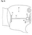
- einen schematischen Schnitt durch die Ausführungsform nach
Fig. 1a in ihrer postoperativen Einbausituation im Mittelohr; - Fig. 2
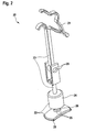
- eine Ausführungsform mit einem Clip als erstem Befestigungselement sowie mit einem Kugelgelenk im Prothesenkörper; und
- Fign. 3a-f
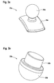
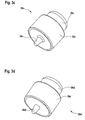
- verschiedene, geometrisch und funktionell unterschiedliche Ausführungsformen des erfindungsgemäßen Einschiebeteils.
- Die in den
Figuren 1a ,1b und2 schematisch dargestellten, im Detail unterschiedlich gestalteten Ausführungsformen der erfindungsgemäßen Mittelohrprothese 10; 20 weisen an ihrem einen Ende jeweils ein erstes Befestigungselement 11; 21 auf. - Dabei ist das Befestigungselement 11 in den
Figuren 1a und1b als Kopfplatte zur Anlage der Prothese am Trommelfell ausgebildet, das Befestigungselement 21 inFig. 2 weist die Form eines Clips zur mechanischen Verbindung am Hammergriff auf. - Am anderen Ende der Mittelohrprothese 10; 20 sitzt jeweils ein zweites Befestigungselement 12; 22 zum mechanischen Ankoppeln der Prothese an der Steigbügelfußplatte. Dazwischen ist ein die beiden Befestigungselemente 11; 21 bzw. 12; 22 Schall leitend miteinander verbindender, als länglicher Schaft ausgebildeter Prothesenkörper 13; 23 angeordnet.
- Das zweite Befestigungselement 12; 22 umfasst jeweils ein als Aufnahmeteil 14; 24 ausgebildetes, starr mit dem Prothesenkörper 13; 23 verbundenes erstes Teilstück sowie ein als Einschiebeteil 15; 25 ausgebildetes zweites Teilstück, welches ein koaxial zur Längsachse des Prothesenkörpers 13; 23 in eine Aufnahmeöffnung des Aufnahmeteils 14; 24 einschiebbares Steckelement 16; 26 sowie einen starr mit dem Steckelement 16; 26 verbundenen Schuh 18; 28 aufweist, der im implantierten Zustand der Prothese 10; 20 auf der Steigbügelfußplatte anliegt
- Erfindungsgemäß weist das Aufnahmeteil 14; 24 an seinem dem Prothesenkörper 13; 23 abgewandten Ende jeweils eine als länglicher Hohlraum 17 ausgebildete Aufnahmeöffnung mit zylindrischer Bohrung auf, die sich in axialer Richtung des Prothesenkörpers 13; 23 erstreckt und das Steckelement 16; 26 des Einschiebeteils 15; 25 im montierten Zustand vollumfänglich umgibt. Der lichte Durchmesser des länglichen Hohlraums 17 ist größer als die maximale Querausdehnung des Steckelements 16; 26 quer zur Längsachse des schaftförmigen Prothesenkörpers 13; 23, der längliche Hohlraum 17 ist in Richtung vom Einschiebeteil 15; 25 weg einseitig geschlossen und wirkt im montierten Zustand als Endanschlag für das Steckelement 16; 26. Das zweite Koppelelement 12; 22 erstreckt sich in axialer Richtung der Prothese maximal ein Drittel, vorzugsweise maximal ein Viertel der axialen Länge des Prothesenkörpers 13; 23.
- In der Ausführungsform nach
Fig.2 ist in den Prothesenkörper 23 ein Kugelgelenk 29 integriert, um eine gewisse postoperative Flexibilität der Mittelohrprothese 20 zwischen ihren Verbindungsstellen zu erreichen.
Die Massenverteilung der einzelnen Teile der erfindungsgemäßen Mittelohrprothese 10; 20 kann in Abhängigkeit von einem gewünschten, vorgebbaren Frequenzgang der Schallleitung im Mittelohr derart berechnet sein, dass ein individuelles Tuning der SchallleitungsEigenschaften ermöglicht wird. - Zumindest abschnittsweise kann eine biologisch aktive Beschichtung, insbesondere eine wachstumshemmende und/oder eine wachstumsfördernde und /oder eine antibakteriell wirkende Beschichtung der Mittelohrprothese 10; 20 vorgesehen sein.
- Bei den Ausführungsformen nach den
Figuren 3a bis 3f weist das Einschiebeteil 35a; 35b; 35c; 35d; 35e; 35f jeweils verschiedene geometrische Gestaltungen auf, die für unterschiedliche, beim Patienten individuell vorgefundene Situationen im Bereich der Steigbügelfußplatte ad hoc eine optimale Anpassung der Mittelohrprothese ermöglichen, wie weiter oben erläutert wurde: - Das Einschiebeteil 35a weist ein kugelförmig verdicktes Steckelement 36a sowie einen konkav gewölbten Schuh 38a auf.
- Das Einschiebeteil 35b umfasst ein zylindrisches Steckelement 36b sowie einen konvex in kugeliger Form nach außen gewölbten Schuh 38b.
- Die Einschiebeteile 35c; 35d weisen jeweils ein i.w. zylindrisches Steckelement 36c; 36d sowie einen flachen Schuh 38c; 38d auf, der auf seinem Endabschnitt jeweils eine im implantierten Zustand der Mittelohrprothese gegen die Steigbügelfußplatte gerichtete Spitze 39c; 39d trägt, wobei der Endabschnitt flach, konkav oder auch konvex gewölbt gestaltet sein kann. Die Spitze 39c in
Fig. 3c ist in ihrem Ansatzbereich am Endabschnitt des Schuhes 38c zusätzlich mit einem ringförmigen Wulst umgeben, der eine großflächige Auflage des Endabschnitts auf der Steigbügelfußplatte verhindert. - Beim Einschiebeteil 35e weist der Schuh 38e einen geringeren maximalen Außenumfang als das Steckelement 36e auf.
- Das Einschiebeteil 35f schließlich umfasst ein hohlzylindrisches Steckelement 36f sowie einen Schuh 38f, der an seinem Außenumfang radial nach innen verlaufende Aussparungen aufweist.
- Außer den in den Figuren der Zeichnung dargestellten Ausführungsformen sind auch noch viele andere geometrische Ausgestaltungen des erfindungsgemäßen Einschiebeteils möglich, beispielsweise die oben beschriebene Variante, bei der der Schuh an seinem Außenumfang radial nach außen ragende Stabilisatorflügel aufweist. Damit können praktisch alle denkbaren individuellen Situationen im Bereich der Steigbügelfußplatte eines Patienten abgedeckt werden.
Claims (15)
- Mittelohrprothese (10; 20) zur totalen Rekonstruktion der menschlichen Gehörknöchelchenkette mit einem schaftförmigen Prothesenkörper (13; 23), an dessen einem Ende ein erstes Koppelelement (11; 21) vorgesehen ist, das entweder als Kopfplatte zur mechanischen Verbindung der Prothese mit dem Trommelfell oder als Clip zum Ankoppeln der Prothese am Hammergriff ausgeführt ist, und an dessen anderem Ende ein zweites Koppelelement (12; 22) zur mechanischen Verbindung der Prothese mit der Steigbügelfußplatte vorgesehen ist, das ein starr mit dem Prothesenkörper (13; 23) verbundenes Aufnahmeteil (14; 24) sowie ein Einschiebeteil (15; 25; 35a; 35b; 35c; 35d; 35e; 35f) umfasst, welches ein koaxial zur Längsachse des schaftförmigen Prothesenkörpers (13; 23) in das Aufnahmeteil (14; 24) einschiebbares Steckelement (16; 26; 36a; 36b; 36c; 36d; 36e; 36f) sowie einen starr mit dem Steckelement (16; 26; 36a; 36b; 36c; 36d; 36e; 36f) verbundenen Schuh (18; 28; 38a; 38b; 38c; 38d; 38e; 38f) aufweist, der im implantierten Zustand der Prothese auf der Steigbügelfußplatte anliegt, dadurch gekennzeichnet, dass das Aufnahmeteil (14; 24) an seinem dem Prothesenkörper (13; 23) abgewandten Ende eine als länglicher Hohlraum (17) ausgebildete Aufnahmeöffnung mit zylindrischer Bohrung aufweist, die sich in axialer Richtung des Prothesenkörpers (13; 23) erstreckt und das Steckelement (16; 26; 36a; 36b; 36c; 36d; 36e; 36f) des Einschiebeteils (15; 25; 35a; 35b; 35c; 35d; 35e; 35f) im montierten Zustand vollumfänglich umgibt, dass der lichte Durchmesser des länglichen Hohlraums (17) größer ist als die maximale Querausdehnung des Steckelements (16; 26; 36a; 36b; 36c; 36d; 36e; 36f) quer zur Längsachse des schaftförmigen Prothesenkörpers (13; 23), dass der längliche Hohlraum (17) in Richtung vom Einschiebeteil (15; 25; 35a; 35b; 35c; 35d; 35e; 35f) weg einseitig geschlossen ist und im montierten Zustand als Endanschlag für das Steckelement (16; 26; 36a; 36b; 36c; 36d; 36e; 36f) wirkt, und dass das zweite Koppelelement (12; 22) sich in axialer Richtung der Prothese maximal ein Drittel der axialen Länge des Prothesenkörpers (13; 23) erstreckt.
- Mittelohrprothese nach Anspruch 1, dadurch gekennzeichnet, dass das Einschiebeteil (15; 25; 35a; 35b; 35c; 35d; 35e; 35f) auf wählbaren diskreten relativen koaxialen Positionen längs einer axialen Strecke mit dem Aufnahmeteil (14; 24) mittels einer äußeren Einwirkung auf das Einschiebeteil (15; 25; 35a; 35b; 35c; 35d; 35e; 35f) und/oder auf das Aufnahmeteil (14; 24) aktiv verklemmbar ist.
- Mittelohrprothese nach Anspruch 2 dadurch gekennzeichnet, dass das Einschiebeteil (15; 25; 35a; 35b; 35c; 35d; 35e; 35f) durch äußere mechanische Krafteinwirkung, insbesondere mittels Einwirkung einer Crimpzange in radialer Richtung auf das Aufnahmeteil (14; 24), mit dem Aufnahmeteil (14; 24) aktiv verklemmbar ist.
- Mittelohrprothese nach Anspruch 2, dadurch gekennzeichnet, dass das Einschiebeteil (15; 25; 35a; 35b; 35c; 35d; 35e; 35f) durch Wärmeeintrag auf die Mittelohrprothese (10; 20) von außen, insbesondere mittels Erwärmung der Prothese auf Körpertemperatur, mit dem Aufnahmeteil (14; 24) aktiv verklemmbar ist.
- Mittelohrprothese nach Anspruch 4, dadurch gekennzeichnet, dass das Einschiebeteil (15; 25; 35a; 35b; 35c; 35d; 35e; 35f) und/oder das Aufnahmeteil (14; 24) ganz oder teilweise aus einem Material mit Formgedächtnis (=memory effect), insbesondere aus Nitinol oder einem Polymer hergestellt ist.
- Mittelohrprothese nach einem der Ansprüche 1 bis 5, dadurch gekennzeichnet, dass das Steckelement (36b; 36c; 36d; 36e; 36f) eine durchgehend zylindrische Form aufweist.
- Mittelohrprothese nach einem der Ansprüche 1 bis 5, dadurch gekennzeichnet, dass das Steckelement (16; 26; 36a) eine an seinem im montierten Zustand dem Aufnahmeteil (14; 24) zugewandten axialen Ende angeordnete Verdickung mit einer ellipsoiden, insbesondere einer rotationsellipsoiden, vorzugsweise einer kugeligen Form aufweist.
- Mittelohrprothese nach einem der vorhergehenden Ansprüche, dadurch gekennzeichnet, dass das Aufnahmeteil (14; 24) in seinem Querschnitt senkrecht zu seiner Längsachse eine zylindrische Außenkontur aufweist.
- Mittelohrprothese nach einem der vorhergehenden Ansprüche, dadurch gekennzeichnet, dass der Prothesenkörper (23) mindestens ein Gelenk, insbesondere ein Kugelgelenk (29), vorzugsweise eine axial verlaufende Kugelgelenkkette aufweist.
- Mittelohrprothese nach einem der vorhergehenden Ansprüche, dadurch gekennzeichnet, dass der starr mit dem Steckelement (16; 26; 36a; 36b; 36c; 36d; 36e; 36f) verbundene Schuh (18; 28; 38a; 38b; 38c; 38d; 38e; 38f), der im implantierten Zustand der Prothese auf der Steigbügelfußplatte anliegt, platten- oder stempelförmig aufgebaut ist.
- Mittelohrprothese nach einem Anspruch 10, dadurch gekennzeichnet, dass der im implantierten Zustand der Mittelohrprothese (10; 20) auf der Steigbügelfußplatte anliegende Endabschnitt des Schuhes (18; 28; 38a; 38b; 38c; 38d; 38e; 38f) eine in Richtung auf das Steckelement (16; 26; 36a) konkav gewölbte Fläche aufweist und/oder flach ausgebildet ist und/oder eine in Richtung vom Steckelement (36b) weg konvex gewölbte Fläche aufweist.
- Mittelohrprothese nach Anspruch 11, dadurch gekennzeichnet, dass der Endabschnitt des Schuhes (38b) eine rotationsellipsoide, vorzugsweise eine kugelige Form aufweist.
- Mittelohrprothese nach einem der Ansprüche 11 oder 12, dadurch gekennzeichnet, dass der Endabschnitt des Schuhes (38c; 38d) eine im implantierten Zustand der Mittelohrprothese gegen die Steigbügelfußplatte gerichtete Spitze (39c; 39d) aufweist.
- Mittelohrprothese nach einem der vorhergehenden Ansprüche, dadurch gekennzeichnet, dass der starr mit dem Steckelement (16; 26; 36a; 36b; 36c; 36d; 36e; 36f) verbundene Schuh (18; 28; 38a; 38b; 38c; 38d; 38e; 38f) an seinem Außenumfang radial nach außen ragende Stabilisatorflügel und/oder radial nach innen verlaufende Aussparungen aufweist und/oder dass der Schuh (38e) einen geringeren maximalen Außenumfang als das Steckelement (36e) aufweist.
- Mittelohrprothese nach einem der vorhergehenden Ansprüche, dadurch gekennzeichnet, dass ein Sortiment von Einschiebeteilen (15; 25; 35a; 35b; 35c; 35d; 35e; 35f) vorgesehen ist, bei welchem die Einschiebeteile (15; 25; 35a; 35b; 35c; 35d; 35e; 35f) in unterschiedlichen geometrischen Ausformungen vorliegen, aber derart ausgebildet sind, dass die Mittelohrprothese (10; 20) nach dem Einschieben des jeweiligen Steckelements (16; 26; 36a; 36b; 36c; 36d; 36e; 36f) eines Einschiebeteils (15; 25; 35a; 35b; 35c; 35d; 35e; 35f) bis zum Endanschlag in den länglichen Hohlraum (17) des Aufnahmeteils (14; 24) jeweils die gleiche axiale Gesamtlänge aufweist.
Applications Claiming Priority (1)
| Application Number | Priority Date | Filing Date | Title |
|---|---|---|---|
| DE102007062151A DE102007062151B3 (de) | 2007-12-21 | 2007-12-21 | Modulare Mittelohr-Totalprothese |
Publications (2)
| Publication Number | Publication Date |
|---|---|
| EP2072026A1 true EP2072026A1 (de) | 2009-06-24 |
| EP2072026B1 EP2072026B1 (de) | 2010-03-24 |
Family
ID=40031068
Family Applications (1)
| Application Number | Title | Priority Date | Filing Date |
|---|---|---|---|
| EP08018714A Active EP2072026B1 (de) | 2007-12-21 | 2008-10-25 | Modulare Mittelohr-Totalprothese |
Country Status (6)
| Country | Link |
|---|---|
| US (1) | US9216081B2 (de) |
| EP (1) | EP2072026B1 (de) |
| CN (1) | CN101461743B (de) |
| AT (1) | ATE461677T1 (de) |
| DE (2) | DE102007062151B3 (de) |
| ES (1) | ES2341143T3 (de) |
Cited By (2)
| Publication number | Priority date | Publication date | Assignee | Title |
|---|---|---|---|---|
| US8685090B2 (en) | 2011-01-29 | 2014-04-01 | Heinz Kurz Gmbh Medizintechnik | Auditory ossicle prosthesis with stabiliser element |
| US10687937B2 (en) | 2016-11-08 | 2020-06-23 | Jack M. Kartush | Systems and methods for performing ossicular chain reconstructions |
Families Citing this family (20)
| Publication number | Priority date | Publication date | Assignee | Title |
|---|---|---|---|---|
| DE102005048618B4 (de) * | 2005-10-11 | 2008-08-21 | Heinz Kurz Gmbh Medizintechnik | Gehörknöchelchenprothese mit elastischem Drehgelenk |
| DE102008015117B3 (de) | 2008-03-20 | 2009-06-04 | Heinz Kurz Gmbh Medizintechnik | Gehörknöchelchenprothese mit variablen Ankopplungsflächen |
| DE102008015115A1 (de) | 2008-03-20 | 2009-10-01 | Heinz Kurz Gmbh Medizintechnik | Gehörknöchelchenprothese mit variablen Ankopplungsflächen |
| DE102008015114B4 (de) | 2008-03-20 | 2009-11-05 | Heinz Kurz Gmbh Medizintechnik | Gehörknöchelchenprothese mit variablen Ankopplungsflächen |
| EP2135584B1 (de) * | 2008-10-21 | 2011-01-19 | Franco Beoni | Mittelohr-Prothesevorrichtung |
| DE102009016468B3 (de) * | 2009-04-10 | 2009-12-24 | Heinz Kurz Gmbh Medizintechnik | Längenvariable Gehörknöchelchenprothese |
| US20110009961A1 (en) * | 2009-07-13 | 2011-01-13 | Gyrus Ent, L.L.C. | Radiopaque middle ear prosthesis |
| DE102010020412B3 (de) * | 2010-05-12 | 2011-06-01 | Heinz Kurz Gmbh Medizintechnik | Testeinrichtung mit Thermo-Dummy für Gehörknöchelchenprothese mit Formgedächtnis |
| DE102010046457B3 (de) * | 2010-09-24 | 2011-07-07 | Heinz Kurz GmbH Medizintechnik, 72144 | Anordnung zur längenvariablen Fixierung des Aktor-Endstücks eines aktiven Hör-Implantats im Mittelohr |
| CN102723316A (zh) * | 2011-03-29 | 2012-10-10 | 北京奇宏科技研发中心有限公司 | 环路热管结构 |
| US8641760B2 (en) | 2011-05-06 | 2014-02-04 | Enteroptyx | Ossicular prosthesis with stabilizer and method of use with intact stapes |
| US8834567B2 (en) * | 2011-08-31 | 2014-09-16 | Mark Matthew Scheurer | Middle ear prosthesis having discrete projections for purposes of ossicular attachment |
| DE102013103484B3 (de) * | 2013-04-08 | 2014-04-17 | Heinz Kurz Gmbh Medizintechnik | Gehörknöchelchenprothese mit aufgefüttertem Befestigungselement |
| DE102013106574A1 (de) | 2013-06-24 | 2014-12-24 | Heinz Kurz Gmbh Medizintechnik | Gehörknöchelchenprothese mit CT- oder MRT-Marker |
| DE202013102732U1 (de) | 2013-06-24 | 2013-07-04 | Heinz Kurz Gmbh Medizintechnik | Gehörknöchelchenprothese mit CT- oder MRT-Marker |
| US10595990B2 (en) | 2016-09-06 | 2020-03-24 | Gyrus Acmi, Inc. | Osseointegrative adjustable ossicular prosthesis |
| EP3512463B1 (de) | 2016-09-13 | 2020-04-22 | Med-El Elektromedizinische Geraete GmbH | Passive mittelohrprothese |
| CN109620470B (zh) * | 2018-12-25 | 2021-07-23 | 苏州真懿精密器械有限公司 | 可更换式人工听骨赝复物装置 |
| DE102021107955A1 (de) * | 2021-03-30 | 2022-10-06 | Med-El Elektromedizinische Geräte GmbH | Gehörknöchelchenprothese |
| CN115670742A (zh) * | 2022-11-10 | 2023-02-03 | 北京大学第一医院 | 可调节人工听骨及其形成方法 |
Citations (8)
| Publication number | Priority date | Publication date | Assignee | Title |
|---|---|---|---|---|
| DE29904770U1 (de) | 1999-03-16 | 1999-06-10 | Spiggle & Theis, 64807 Dieburg | Mittelohrimplantat, ausgebildet als Teilprothese |
| WO1999042060A1 (de) * | 1998-02-18 | 1999-08-26 | Spiggle & Theis | Mittelohrimplantat |
| DE20014659U1 (de) * | 2000-08-24 | 2000-11-30 | Heinz Kurz GmbH Medizintechnik, 72144 Dußlingen | Vorrichtung zum Ankoppeln |
| US6168625B1 (en) * | 1998-12-01 | 2001-01-02 | Anthony D. Prescott | Adjustable length prosthesis useful for ossicular replacement and reconstruction |
| WO2002069850A1 (en) | 2001-03-02 | 2002-09-12 | Gyrus Ent L.L.C. | Otologic prosthesis |
| DE20310609U1 (de) | 2003-07-10 | 2003-09-18 | Heinz Kurz GmbH Medizintechnik, 72144 Dußlingen | Gehörknöchelchenprothese mit integriertem Kugelgelenk |
| DE202004012148U1 (de) | 2004-08-03 | 2004-12-16 | Heckmann, Walter | Mittelohrimplantat |
| DE202007012217U1 (de) | 2007-08-31 | 2007-11-29 | Heinz Kurz Gmbh Medizintechnik | Längenvariable Gehörknöchelchenprothese |
Family Cites Families (4)
| Publication number | Priority date | Publication date | Assignee | Title |
|---|---|---|---|---|
| US4601723A (en) * | 1985-01-29 | 1986-07-22 | Mcgrew Robert N | Telescoping self-adjusting ossicular prostheses |
| FR2579887A1 (de) * | 1985-04-05 | 1986-10-10 | France Implant Sarl | |
| IT1248737B (it) * | 1990-06-07 | 1995-01-26 | Franco Beoni | Protesi di orecchio medio |
| CN1171567C (zh) * | 2002-02-28 | 2004-10-20 | 周星 | 记忆合金人工听骨 |
-
2007
- 2007-12-21 DE DE102007062151A patent/DE102007062151B3/de not_active Expired - Fee Related
-
2008
- 2008-10-25 DE DE502008000471T patent/DE502008000471D1/de active Active
- 2008-10-25 AT AT08018714T patent/ATE461677T1/de active
- 2008-10-25 ES ES08018714T patent/ES2341143T3/es active Active
- 2008-10-25 EP EP08018714A patent/EP2072026B1/de active Active
- 2008-11-20 US US12/313,388 patent/US9216081B2/en active Active
- 2008-11-28 CN CN2008101823778A patent/CN101461743B/zh active Active
Patent Citations (10)
| Publication number | Priority date | Publication date | Assignee | Title |
|---|---|---|---|---|
| WO1999042060A1 (de) * | 1998-02-18 | 1999-08-26 | Spiggle & Theis | Mittelohrimplantat |
| US6168625B1 (en) * | 1998-12-01 | 2001-01-02 | Anthony D. Prescott | Adjustable length prosthesis useful for ossicular replacement and reconstruction |
| US6554861B2 (en) | 1999-01-19 | 2003-04-29 | Gyrus Ent L.L.C. | Otologic prosthesis |
| DE29904770U1 (de) | 1999-03-16 | 1999-06-10 | Spiggle & Theis, 64807 Dieburg | Mittelohrimplantat, ausgebildet als Teilprothese |
| DE20014659U1 (de) * | 2000-08-24 | 2000-11-30 | Heinz Kurz GmbH Medizintechnik, 72144 Dußlingen | Vorrichtung zum Ankoppeln |
| EP1181907B1 (de) | 2000-08-24 | 2004-05-12 | Heinz Kurz GmbH Medizintechnik | Gehörknöchelchenprothese |
| WO2002069850A1 (en) | 2001-03-02 | 2002-09-12 | Gyrus Ent L.L.C. | Otologic prosthesis |
| DE20310609U1 (de) | 2003-07-10 | 2003-09-18 | Heinz Kurz GmbH Medizintechnik, 72144 Dußlingen | Gehörknöchelchenprothese mit integriertem Kugelgelenk |
| DE202004012148U1 (de) | 2004-08-03 | 2004-12-16 | Heckmann, Walter | Mittelohrimplantat |
| DE202007012217U1 (de) | 2007-08-31 | 2007-11-29 | Heinz Kurz Gmbh Medizintechnik | Längenvariable Gehörknöchelchenprothese |
Cited By (2)
| Publication number | Priority date | Publication date | Assignee | Title |
|---|---|---|---|---|
| US8685090B2 (en) | 2011-01-29 | 2014-04-01 | Heinz Kurz Gmbh Medizintechnik | Auditory ossicle prosthesis with stabiliser element |
| US10687937B2 (en) | 2016-11-08 | 2020-06-23 | Jack M. Kartush | Systems and methods for performing ossicular chain reconstructions |
Also Published As
| Publication number | Publication date |
|---|---|
| DE502008000471D1 (de) | 2010-05-06 |
| ATE461677T1 (de) | 2010-04-15 |
| US20090164010A1 (en) | 2009-06-25 |
| ES2341143T3 (es) | 2010-06-15 |
| CN101461743B (zh) | 2012-05-16 |
| US9216081B2 (en) | 2015-12-22 |
| CN101461743A (zh) | 2009-06-24 |
| EP2072026B1 (de) | 2010-03-24 |
| DE102007062151B3 (de) | 2008-12-24 |
Similar Documents
| Publication | Publication Date | Title |
|---|---|---|
| EP2072026B1 (de) | Modulare Mittelohr-Totalprothese | |
| EP2238946B1 (de) | Längenvariable Gehörknöchelchenprothese | |
| EP2601909B1 (de) | Längenvariable passive Gehörknöchelchenprothese | |
| DE102007041539B4 (de) | Längenvariable Gehörknöchelchenprothese | |
| DE102007013708B3 (de) | Gehörknöchelchenprothese mit sensibler Kopfplatte | |
| EP2210572B1 (de) | Passive Gehörknöchelchenprothese mit Applikator | |
| EP2103280B1 (de) | Gehörknöchelchenprothese mit variablen Ankopplungsflächen | |
| EP3130315B1 (de) | Laser-aktivierbare längenvariable gehörknöchelchenprothese | |
| EP2103282B1 (de) | Gehörknöchelchenprothese mit variablen Ankopplungsflächen | |
| EP2434778B1 (de) | Anordnung zur längenvariablen Fixierung des Aktor-Endstücks eines aktiven Hör-Implantats im Mittelohr | |
| DE102005010705B3 (de) | Gehörknöchelchenprothese | |
| DE202007012217U1 (de) | Längenvariable Gehörknöchelchenprothese | |
| DE202007017910U1 (de) | Modulare Mittelohr-Totalprothese | |
| EP2103281B1 (de) | Gehörknöchelchenprothese mit variablen Ankopplungsflächen | |
| EP2926771B1 (de) | Gehörknöchelchenprothese mit längs-perforierter Schlinge | |
| DE102005048618A1 (de) | Gehörknöchelchenprothese mit elastischem Drehgelenk | |
| DE202008003887U1 (de) | Gehörknöchelchenprothese mit variablen Ankopplungsflächen | |
| EP3427694B1 (de) | Selbstklemmende kopfplatte für eine gehörknöchelchenprothese | |
| DE202005003782U1 (de) | Gehörknöchelchenprothese | |
| DE102024121204B3 (de) | Aus einem Gebinde auswählbare Gehörknöchelchenprothese | |
| EP4292568B1 (de) | Längenverstellbare gehörknöchelchenprothese mit in-situ-elongation aus der kopfplatte heraus | |
| DE202009004715U1 (de) | Längenvariable Gehörknöchelchenprothese | |
| DE202008003885U1 (de) | Gehörknöchelchenprothese mit variablen Ankopplungsflächen | |
| EP4316424A1 (de) | Verbesserte längenverstellbare gehörknöchelchenprothese mit in-situ-elongation aus der kopfplatte heraus | |
| DE202008003890U1 (de) | Gehörknöchelchenprothese mit variablen Ankopplungsflächen |
Legal Events
| Date | Code | Title | Description |
|---|---|---|---|
| PUAI | Public reference made under article 153(3) epc to a published international application that has entered the european phase |
Free format text: ORIGINAL CODE: 0009012 |
|
| AK | Designated contracting states |
Kind code of ref document: A1 Designated state(s): AT BE BG CH CY CZ DE DK EE ES FI FR GB GR HR HU IE IS IT LI LT LU LV MC MT NL NO PL PT RO SE SI SK TR |
|
| AX | Request for extension of the european patent |
Extension state: AL BA MK RS |
|
| 17P | Request for examination filed |
Effective date: 20090515 |
|
| GRAP | Despatch of communication of intention to grant a patent |
Free format text: ORIGINAL CODE: EPIDOSNIGR1 |
|
| GRAS | Grant fee paid |
Free format text: ORIGINAL CODE: EPIDOSNIGR3 |
|
| GRAA | (expected) grant |
Free format text: ORIGINAL CODE: 0009210 |
|
| AKX | Designation fees paid |
Designated state(s): AT BE BG CH CY CZ DE DK EE ES FI FR GB GR HR HU IE IS IT LI LT LU LV MC MT NL NO PL PT RO SE SI SK TR |
|
| AK | Designated contracting states |
Kind code of ref document: B1 Designated state(s): AT BE BG CH CY CZ DE DK EE ES FI FR GB GR HR HU IE IS IT LI LT LU LV MC MT NL NO PL PT RO SE SI SK TR |
|
| REG | Reference to a national code |
Ref country code: GB Ref legal event code: FG4D Free format text: NOT ENGLISH |
|
| REG | Reference to a national code |
Ref country code: CH Ref legal event code: EP |
|
| REG | Reference to a national code |
Ref country code: IE Ref legal event code: FG4D |
|
| REF | Corresponds to: |
Ref document number: 502008000471 Country of ref document: DE Date of ref document: 20100506 Kind code of ref document: P |
|
| REG | Reference to a national code |
Ref country code: ES Ref legal event code: FG2A Ref document number: 2341143 Country of ref document: ES Kind code of ref document: T3 |
|
| REG | Reference to a national code |
Ref country code: NL Ref legal event code: T3 |
|
| PG25 | Lapsed in a contracting state [announced via postgrant information from national office to epo] |
Ref country code: NO Free format text: LAPSE BECAUSE OF FAILURE TO SUBMIT A TRANSLATION OF THE DESCRIPTION OR TO PAY THE FEE WITHIN THE PRESCRIBED TIME-LIMIT Effective date: 20100624 Ref country code: HR Free format text: LAPSE BECAUSE OF FAILURE TO SUBMIT A TRANSLATION OF THE DESCRIPTION OR TO PAY THE FEE WITHIN THE PRESCRIBED TIME-LIMIT Effective date: 20100324 Ref country code: LT Free format text: LAPSE BECAUSE OF FAILURE TO SUBMIT A TRANSLATION OF THE DESCRIPTION OR TO PAY THE FEE WITHIN THE PRESCRIBED TIME-LIMIT Effective date: 20100324 |
|
| LTIE | Lt: invalidation of european patent or patent extension |
Effective date: 20100324 |
|
| PG25 | Lapsed in a contracting state [announced via postgrant information from national office to epo] |
Ref country code: PL Free format text: LAPSE BECAUSE OF FAILURE TO SUBMIT A TRANSLATION OF THE DESCRIPTION OR TO PAY THE FEE WITHIN THE PRESCRIBED TIME-LIMIT Effective date: 20100324 Ref country code: FI Free format text: LAPSE BECAUSE OF FAILURE TO SUBMIT A TRANSLATION OF THE DESCRIPTION OR TO PAY THE FEE WITHIN THE PRESCRIBED TIME-LIMIT Effective date: 20100324 Ref country code: LV Free format text: LAPSE BECAUSE OF FAILURE TO SUBMIT A TRANSLATION OF THE DESCRIPTION OR TO PAY THE FEE WITHIN THE PRESCRIBED TIME-LIMIT Effective date: 20100324 Ref country code: SI Free format text: LAPSE BECAUSE OF FAILURE TO SUBMIT A TRANSLATION OF THE DESCRIPTION OR TO PAY THE FEE WITHIN THE PRESCRIBED TIME-LIMIT Effective date: 20100324 |
|
| REG | Reference to a national code |
Ref country code: IE Ref legal event code: FD4D |
|
| PG25 | Lapsed in a contracting state [announced via postgrant information from national office to epo] |
Ref country code: RO Free format text: LAPSE BECAUSE OF FAILURE TO SUBMIT A TRANSLATION OF THE DESCRIPTION OR TO PAY THE FEE WITHIN THE PRESCRIBED TIME-LIMIT Effective date: 20100324 Ref country code: SE Free format text: LAPSE BECAUSE OF FAILURE TO SUBMIT A TRANSLATION OF THE DESCRIPTION OR TO PAY THE FEE WITHIN THE PRESCRIBED TIME-LIMIT Effective date: 20100324 Ref country code: GR Free format text: LAPSE BECAUSE OF FAILURE TO SUBMIT A TRANSLATION OF THE DESCRIPTION OR TO PAY THE FEE WITHIN THE PRESCRIBED TIME-LIMIT Effective date: 20100625 Ref country code: EE Free format text: LAPSE BECAUSE OF FAILURE TO SUBMIT A TRANSLATION OF THE DESCRIPTION OR TO PAY THE FEE WITHIN THE PRESCRIBED TIME-LIMIT Effective date: 20100324 |
|
| PG25 | Lapsed in a contracting state [announced via postgrant information from national office to epo] |
Ref country code: IS Free format text: LAPSE BECAUSE OF FAILURE TO SUBMIT A TRANSLATION OF THE DESCRIPTION OR TO PAY THE FEE WITHIN THE PRESCRIBED TIME-LIMIT Effective date: 20100724 Ref country code: SK Free format text: LAPSE BECAUSE OF FAILURE TO SUBMIT A TRANSLATION OF THE DESCRIPTION OR TO PAY THE FEE WITHIN THE PRESCRIBED TIME-LIMIT Effective date: 20100324 Ref country code: BG Free format text: LAPSE BECAUSE OF FAILURE TO SUBMIT A TRANSLATION OF THE DESCRIPTION OR TO PAY THE FEE WITHIN THE PRESCRIBED TIME-LIMIT Effective date: 20100624 |
|
| PLBE | No opposition filed within time limit |
Free format text: ORIGINAL CODE: 0009261 |
|
| STAA | Information on the status of an ep patent application or granted ep patent |
Free format text: STATUS: NO OPPOSITION FILED WITHIN TIME LIMIT |
|
| PG25 | Lapsed in a contracting state [announced via postgrant information from national office to epo] |
Ref country code: DK Free format text: LAPSE BECAUSE OF FAILURE TO SUBMIT A TRANSLATION OF THE DESCRIPTION OR TO PAY THE FEE WITHIN THE PRESCRIBED TIME-LIMIT Effective date: 20100324 Ref country code: IE Free format text: LAPSE BECAUSE OF FAILURE TO SUBMIT A TRANSLATION OF THE DESCRIPTION OR TO PAY THE FEE WITHIN THE PRESCRIBED TIME-LIMIT Effective date: 20100324 |
|
| 26N | No opposition filed |
Effective date: 20101228 |
|
| BERE | Be: lapsed |
Owner name: HEINZ KURZ G.M.B.H. MEDIZINTECHNIK Effective date: 20101031 |
|
| PG25 | Lapsed in a contracting state [announced via postgrant information from national office to epo] |
Ref country code: MC Free format text: LAPSE BECAUSE OF NON-PAYMENT OF DUE FEES Effective date: 20101031 |
|
| PG25 | Lapsed in a contracting state [announced via postgrant information from national office to epo] |
Ref country code: BE Free format text: LAPSE BECAUSE OF NON-PAYMENT OF DUE FEES Effective date: 20101031 |
|
| PG25 | Lapsed in a contracting state [announced via postgrant information from national office to epo] |
Ref country code: MT Free format text: LAPSE BECAUSE OF FAILURE TO SUBMIT A TRANSLATION OF THE DESCRIPTION OR TO PAY THE FEE WITHIN THE PRESCRIBED TIME-LIMIT Effective date: 20100324 |
|
| PG25 | Lapsed in a contracting state [announced via postgrant information from national office to epo] |
Ref country code: CY Free format text: LAPSE BECAUSE OF FAILURE TO SUBMIT A TRANSLATION OF THE DESCRIPTION OR TO PAY THE FEE WITHIN THE PRESCRIBED TIME-LIMIT Effective date: 20100324 |
|
| PG25 | Lapsed in a contracting state [announced via postgrant information from national office to epo] |
Ref country code: LU Free format text: LAPSE BECAUSE OF NON-PAYMENT OF DUE FEES Effective date: 20101025 Ref country code: HU Free format text: LAPSE BECAUSE OF FAILURE TO SUBMIT A TRANSLATION OF THE DESCRIPTION OR TO PAY THE FEE WITHIN THE PRESCRIBED TIME-LIMIT Effective date: 20100925 |
|
| PG25 | Lapsed in a contracting state [announced via postgrant information from national office to epo] |
Ref country code: TR Free format text: LAPSE BECAUSE OF FAILURE TO SUBMIT A TRANSLATION OF THE DESCRIPTION OR TO PAY THE FEE WITHIN THE PRESCRIBED TIME-LIMIT Effective date: 20100324 |
|
| REG | Reference to a national code |
Ref country code: CH Ref legal event code: PL |
|
| PG25 | Lapsed in a contracting state [announced via postgrant information from national office to epo] |
Ref country code: PT Free format text: LAPSE BECAUSE OF NON-PAYMENT OF DUE FEES Effective date: 20100324 Ref country code: LI Free format text: LAPSE BECAUSE OF NON-PAYMENT OF DUE FEES Effective date: 20121031 Ref country code: CH Free format text: LAPSE BECAUSE OF NON-PAYMENT OF DUE FEES Effective date: 20121031 |
|
| REG | Reference to a national code |
Ref country code: AT Ref legal event code: MM01 Ref document number: 461677 Country of ref document: AT Kind code of ref document: T Effective date: 20131025 |
|
| PG25 | Lapsed in a contracting state [announced via postgrant information from national office to epo] |
Ref country code: AT Free format text: LAPSE BECAUSE OF NON-PAYMENT OF DUE FEES Effective date: 20131025 |
|
| REG | Reference to a national code |
Ref country code: FR Ref legal event code: PLFP Year of fee payment: 8 |
|
| PGFP | Annual fee paid to national office [announced via postgrant information from national office to epo] |
Ref country code: CZ Payment date: 20150925 Year of fee payment: 8 |
|
| PGFP | Annual fee paid to national office [announced via postgrant information from national office to epo] |
Ref country code: ES Payment date: 20151007 Year of fee payment: 8 |
|
| REG | Reference to a national code |
Ref country code: FR Ref legal event code: PLFP Year of fee payment: 9 |
|
| PG25 | Lapsed in a contracting state [announced via postgrant information from national office to epo] |
Ref country code: CZ Free format text: LAPSE BECAUSE OF NON-PAYMENT OF DUE FEES Effective date: 20161025 |
|
| REG | Reference to a national code |
Ref country code: FR Ref legal event code: PLFP Year of fee payment: 10 |
|
| PG25 | Lapsed in a contracting state [announced via postgrant information from national office to epo] |
Ref country code: ES Free format text: LAPSE BECAUSE OF NON-PAYMENT OF DUE FEES Effective date: 20161026 |
|
| REG | Reference to a national code |
Ref country code: FR Ref legal event code: PLFP Year of fee payment: 11 |
|
| REG | Reference to a national code |
Ref country code: ES Ref legal event code: FD2A Effective date: 20181122 |
|
| PGFP | Annual fee paid to national office [announced via postgrant information from national office to epo] |
Ref country code: IT Payment date: 20211029 Year of fee payment: 14 |
|
| PG25 | Lapsed in a contracting state [announced via postgrant information from national office to epo] |
Ref country code: IT Free format text: LAPSE BECAUSE OF NON-PAYMENT OF DUE FEES Effective date: 20221025 |
|
| PGFP | Annual fee paid to national office [announced via postgrant information from national office to epo] |
Ref country code: GB Payment date: 20231025 Year of fee payment: 16 |
|
| PGFP | Annual fee paid to national office [announced via postgrant information from national office to epo] |
Ref country code: FR Payment date: 20231023 Year of fee payment: 16 |
|
| PGFP | Annual fee paid to national office [announced via postgrant information from national office to epo] |
Ref country code: NL Payment date: 20241023 Year of fee payment: 17 |
|
| GBPC | Gb: european patent ceased through non-payment of renewal fee |
Effective date: 20241025 |
|
| PG25 | Lapsed in a contracting state [announced via postgrant information from national office to epo] |
Ref country code: GB Free format text: LAPSE BECAUSE OF NON-PAYMENT OF DUE FEES Effective date: 20241025 |
|
| PG25 | Lapsed in a contracting state [announced via postgrant information from national office to epo] |
Ref country code: FR Free format text: LAPSE BECAUSE OF NON-PAYMENT OF DUE FEES Effective date: 20241031 |
|
| PGFP | Annual fee paid to national office [announced via postgrant information from national office to epo] |
Ref country code: DE Payment date: 20251022 Year of fee payment: 18 |