EP2072100A1 - Module de distillation incliné multi-effet doté de moyens de chauffage et de refroidissement - Google Patents
Module de distillation incliné multi-effet doté de moyens de chauffage et de refroidissement Download PDFInfo
- Publication number
- EP2072100A1 EP2072100A1 EP07123879A EP07123879A EP2072100A1 EP 2072100 A1 EP2072100 A1 EP 2072100A1 EP 07123879 A EP07123879 A EP 07123879A EP 07123879 A EP07123879 A EP 07123879A EP 2072100 A1 EP2072100 A1 EP 2072100A1
- Authority
- EP
- European Patent Office
- Prior art keywords
- sheet member
- module
- members
- module according
- stage
- Prior art date
- Legal status (The legal status is an assumption and is not a legal conclusion. Google has not performed a legal analysis and makes no representation as to the accuracy of the status listed.)
- Withdrawn
Links
- 238000004821 distillation Methods 0.000 title claims abstract description 32
- 238000010438 heat treatment Methods 0.000 title claims abstract description 29
- 238000001816 cooling Methods 0.000 title description 4
- 239000007788 liquid Substances 0.000 claims abstract description 44
- 239000012530 fluid Substances 0.000 claims abstract description 31
- XLYOFNOQVPJJNP-UHFFFAOYSA-N water Substances O XLYOFNOQVPJJNP-UHFFFAOYSA-N 0.000 claims abstract description 13
- 239000012809 cooling fluid Substances 0.000 claims abstract description 12
- 230000000694 effects Effects 0.000 claims abstract description 12
- 239000005341 toughened glass Substances 0.000 claims abstract description 4
- 239000011521 glass Substances 0.000 claims description 25
- 238000000034 method Methods 0.000 claims description 5
- 239000011248 coating agent Substances 0.000 claims description 4
- 238000000576 coating method Methods 0.000 claims description 4
- 229920001084 poly(chloroprene) Polymers 0.000 claims description 3
- 239000013505 freshwater Substances 0.000 claims description 2
- 230000000284 resting effect Effects 0.000 claims 1
- 239000003566 sealing material Substances 0.000 claims 1
- 239000000110 cooling liquid Substances 0.000 abstract description 2
- 238000007789 sealing Methods 0.000 description 11
- 239000006260 foam Substances 0.000 description 5
- 239000000463 material Substances 0.000 description 5
- 230000007423 decrease Effects 0.000 description 4
- 238000001704 evaporation Methods 0.000 description 4
- 239000004744 fabric Substances 0.000 description 4
- 238000009833 condensation Methods 0.000 description 3
- 230000005494 condensation Effects 0.000 description 3
- 238000010276 construction Methods 0.000 description 3
- 230000008020 evaporation Effects 0.000 description 3
- 230000005484 gravity Effects 0.000 description 3
- 238000012423 maintenance Methods 0.000 description 3
- 238000004519 manufacturing process Methods 0.000 description 3
- 239000013535 sea water Substances 0.000 description 3
- 229910000831 Steel Inorganic materials 0.000 description 2
- 238000009835 boiling Methods 0.000 description 2
- 210000003298 dental enamel Anatomy 0.000 description 2
- 238000000605 extraction Methods 0.000 description 2
- 238000001746 injection moulding Methods 0.000 description 2
- 229920003023 plastic Polymers 0.000 description 2
- 230000000630 rising effect Effects 0.000 description 2
- 239000010959 steel Substances 0.000 description 2
- RYGMFSIKBFXOCR-UHFFFAOYSA-N Copper Chemical compound [Cu] RYGMFSIKBFXOCR-UHFFFAOYSA-N 0.000 description 1
- 229920000877 Melamine resin Polymers 0.000 description 1
- 241001074085 Scophthalmus aquosus Species 0.000 description 1
- 230000015572 biosynthetic process Effects 0.000 description 1
- 239000000919 ceramic Substances 0.000 description 1
- 210000001520 comb Anatomy 0.000 description 1
- 229910052802 copper Inorganic materials 0.000 description 1
- 239000010949 copper Substances 0.000 description 1
- 238000005260 corrosion Methods 0.000 description 1
- 230000007797 corrosion Effects 0.000 description 1
- 239000012153 distilled water Substances 0.000 description 1
- 238000009826 distribution Methods 0.000 description 1
- 229920001971 elastomer Polymers 0.000 description 1
- 238000005530 etching Methods 0.000 description 1
- 238000002474 experimental method Methods 0.000 description 1
- 238000001914 filtration Methods 0.000 description 1
- 235000015203 fruit juice Nutrition 0.000 description 1
- JDSHMPZPIAZGSV-UHFFFAOYSA-N melamine Chemical compound NC1=NC(N)=NC(N)=N1 JDSHMPZPIAZGSV-UHFFFAOYSA-N 0.000 description 1
- 238000000465 moulding Methods 0.000 description 1
- 238000003825 pressing Methods 0.000 description 1
- 230000008439 repair process Effects 0.000 description 1
- 229910001220 stainless steel Inorganic materials 0.000 description 1
- 239000010935 stainless steel Substances 0.000 description 1
- 238000003860 storage Methods 0.000 description 1
- 229920002994 synthetic fiber Polymers 0.000 description 1
- 239000002918 waste heat Substances 0.000 description 1
- 230000003313 weakening effect Effects 0.000 description 1
Images


Classifications
-
- B—PERFORMING OPERATIONS; TRANSPORTING
- B01—PHYSICAL OR CHEMICAL PROCESSES OR APPARATUS IN GENERAL
- B01D—SEPARATION
- B01D1/00—Evaporating
- B01D1/0011—Heating features
- B01D1/0029—Use of radiation
- B01D1/0035—Solar energy
-
- B—PERFORMING OPERATIONS; TRANSPORTING
- B01—PHYSICAL OR CHEMICAL PROCESSES OR APPARATUS IN GENERAL
- B01D—SEPARATION
- B01D1/00—Evaporating
- B01D1/22—Evaporating by bringing a thin layer of the liquid into contact with a heated surface
- B01D1/221—Composite plate evaporators
-
- B—PERFORMING OPERATIONS; TRANSPORTING
- B01—PHYSICAL OR CHEMICAL PROCESSES OR APPARATUS IN GENERAL
- B01D—SEPARATION
- B01D1/00—Evaporating
- B01D1/26—Multiple-effect evaporating
-
- B—PERFORMING OPERATIONS; TRANSPORTING
- B01—PHYSICAL OR CHEMICAL PROCESSES OR APPARATUS IN GENERAL
- B01D—SEPARATION
- B01D5/00—Condensation of vapours; Recovering volatile solvents by condensation
- B01D5/0003—Condensation of vapours; Recovering volatile solvents by condensation by using heat-exchange surfaces for indirect contact between gases or vapours and the cooling medium
- B01D5/0015—Plates
-
- C—CHEMISTRY; METALLURGY
- C02—TREATMENT OF WATER, WASTE WATER, SEWAGE, OR SLUDGE
- C02F—TREATMENT OF WATER, WASTE WATER, SEWAGE, OR SLUDGE
- C02F1/00—Treatment of water, waste water, or sewage
- C02F1/02—Treatment of water, waste water, or sewage by heating
- C02F1/04—Treatment of water, waste water, or sewage by heating by distillation or evaporation
- C02F1/14—Treatment of water, waste water, or sewage by heating by distillation or evaporation using solar energy
-
- Y—GENERAL TAGGING OF NEW TECHNOLOGICAL DEVELOPMENTS; GENERAL TAGGING OF CROSS-SECTIONAL TECHNOLOGIES SPANNING OVER SEVERAL SECTIONS OF THE IPC; TECHNICAL SUBJECTS COVERED BY FORMER USPC CROSS-REFERENCE ART COLLECTIONS [XRACs] AND DIGESTS
- Y02—TECHNOLOGIES OR APPLICATIONS FOR MITIGATION OR ADAPTATION AGAINST CLIMATE CHANGE
- Y02A—TECHNOLOGIES FOR ADAPTATION TO CLIMATE CHANGE
- Y02A20/00—Water conservation; Efficient water supply; Efficient water use
- Y02A20/20—Controlling water pollution; Waste water treatment
- Y02A20/208—Off-grid powered water treatment
- Y02A20/212—Solar-powered wastewater sewage treatment, e.g. spray evaporation
Definitions
- the present invention relates to a tilted multi effect distillation module comprising a plurality of distillation stages, each stage being defined by a first and a second sheet member arranged in parallel to each other, the second sheet member above the first sheet member, and by one or more frame members enclosing the space between the sheet members, and each stage comprising an inlet for supplying feed liquid to the upper surface of the first sheet member at one end thereof, at least one first outlet for extracting residual water at the other end of the first sheet member, and at least one second outlet for extracting water condensating on the second sheet member, and where the sheet member serving as the first sheet member of one stage also serves as the second sheet member in the stage located directly below it.
- the invention further relates to a system comprising such a module and to a method of increasing its efficiency.
- Such a distillation module is known for example from WO2006/002636 . Even though this module has many advantages in comparison with its predecessors it suffers from being of a technically demanding construction. This not only makes it expensive to make, it also limits the possibilities for local manufacturing in lesser-developed countries and for do-it-yourself maintenance and repairs.
- the first object is achieved with a module, where the sheet members are plane, uninterrupted plates of tempered glass.
- the sheet members are provided with one or more holes to allow the introduction and extraction of liquids and to provide a vapour connection between the different stages. This not only makes the manufacture of the sheet members more complicated, but surprisingly also makes the module less effective.
- the use of the uninterrupted plates allows a very simple and easy assembling of the module.
- the glass sheets can simply be clamped between plate-shaped side frame members, which are possibly covered with a sealing surface coating, for example neoprene.
- they may be interconnected using a strip-like sealing, much in the same way as when making a two-sheet windowpane.
- the module can be easily disassembled, e.g. by using a strip-like sealing which is attached to a sheet member only on one side.
- Prior art distillation modules have often been made with sheet members of for example stainless steel covered with enamel. Sea water heated to a temperature of approximately 90°C will, however, soon penetrate microscopic holes or other weakenings in the enamel, causing corrosion of the steel. Glass, on the contrary, tolerates even very aggressive liquids without the need for any kind of surface coating and is almost totally inert, thus not giving anything off to the condensate, as would be the case with most synthetic materials.
- tempered glass is available in virtually all parts of the world, whereas enamelled steel will have to be ordered from a specialist. Furthermore, the glass can be cut to size, whereas a surface coated material will have to be manufactured in the exact right size. Similar considerations apply to sheet members being encased in a frame of a plastic material as is known from WO2006/002636 .
- the simple construction and easy assembly of the module will usually prompt a more regular maintenance, which in return will increase its overall efficiency seen over a longer period of time, thus also achieving the second object of the invention.
- the heating was achieved by solar heated water evaporating from an open tank underneath the module and condensating on its lowermost surface. This method is very simple, but heat lost from the tank decreases the energy reuse factor.
- the first sheet member of the lowermost stage rest on a bottom element, which comprises a bottom plate and one or more distance members keeping the first sheet member at a predetermined distance from the bottom plate, so that a space is formed between them, said space being connected to a heating fluid inlet at the top of the bottom element and to a heating fluid outlet at the bottom of the bottom element.
- a hot fluid is led trough the heating fluid inlet, it enters the space between the bottom plate and the lowermost sheet member, thus coming into direct contact with the latter and heating it directly.
- distance members arranged between the bottom plate and the lowermost sheet member define a bottom frame surrounding the space between the bottom plate and the first sheet member, said frame providing a seal towards the ambient, and where the heating fluid inlet and the heating fluid outlet are formed in the bottom frame.
- this is achieved by arranging the distance members so that they define a serpentine path from the heating fluid inlet to the heating fluid outlet.
- the temperature difference between the upper and lower sheet member of each stage and thus also between the upper and lower side of the entire module has been shown to be one of the most important factors in increasing the efficiency of the system. It is therefore advantageous not only to supply as much energy to the lowermost stage as possible, but also to keep the uppermost stage as cold as possible. In most prior art systems this is achieved by shading the upper side of the module and possibly establishing an air flow over the upper side. In a very hot climate this may, however, not be very efficient and it is therefore suggested to cool the upper side with a liquid.
- the module according to the invention can be equipped with a top element corresponding closely to the bottom element described above, but intended for leading a cooling liquid over the outer surface of the uppermost sheet member.
- a more traditional system of copper tubing or the like may of course also be used for the heating and cooling described above, but due to the poorer contact with the sheet member surface, this will be less efficient.
- the cooling therefore is instead achieved by leading the feed liquid over the upper side of the module, thus using the excess heat radiating from the uppermost stage for heating the feed liquid, the fluid inlet being connected to a feed liquid source and the cooling fluid outlet being connected to the inlet of at least one stage.
- the reuse of energy is taken even a step further in that no additional energy has to be supplied for heating the feed liquid and that virtually no energy is lost in the form of waste heat.
- temperatures should at optimum be close to the boiling point and the optimum temperature difference form stage to the next will normally be approximately 3-5°C.
- temperatures below 50°C the evaporation ratio and vapour content in air are so low that the amount of condensate produced is not sufficiently large to justify another stage.
- the number of stages will therefore normally be limited to approximately 10-15.
- one or more separator members are arranged between the two sheet members of each stage.
- the inlet is formed in or connected to a top separator member and the second outlet, intended for the condensed liquid, is formed in or connected to a bottom separator member.
- the bottom separator member should also be shaped so that non-evaporated liquid can pass beneath it and exit the module.
- Each separator member preferably seals the stage against the ambient, so that no separate sealing is necessary at the top and the bottom of the stage.
- Such separator members can easily be made from plastic by injection moulding as will be explained in further detail below.
- a rubber strip can be added.
- the separator members may also serve as distance keepers, keeping the two sheet members apart. In this way all functionalities necessary for each stage is integrated in the separator member.
- the module can thus be build by simple stacking a series of elements, which can each be made locally from common materials and at low cost.
- the heating fluid use for heating the module may in principle come from any available source, such as a geothermal water, but in a preferred embodiment the module is used together with a solar collector of the thermo siphon type.
- the distillation module may advantageously be arranged underneath the solar collector, where it is shaded from the sun. In this way the piping needed for connecting the two can also be kept as short as possible leading to a minimal heat loss, particularly if the distillation module is attached to the underside of the solar collector. In this way the distillation module and the solar collector may form a unit capable of supplying both freshwater made by distillation and hot water.
- a pump may be necessary for supplying the feed liquid to the distillation module.
- the system may include a photovoltaic element supplying energy to the pump, thus making the system independent of external power sources, which may not be available or be unreliable.
- the distillation module according to the invention is formed by a series of stages, which in the preferred embodiment each comprises a glass plate 1, a top separator member 2 and a bottom separator member 3.
- the glass must be tempered to be able to withstand the sudden increase in temperature, when distillation is initiated and hot feed liquid is entering the not yet heated system.
- An inlet 21 for supplying feed liquid to the stage is integrated in the top separator member and an outlet 31 for extracting condensate is integrated in the bottom separator.
- Both separator members are preferably made by injection moulding and the inlet and outlet, respectively, can be a part of the moulded item, be embedded in the moulding material or be attached subsequently.
- the glass plate 1 is covered by a piece of fabric 4, preferably a non-woven, also known as a wick, which absorbs the liquid and thus prevents the formation of streams.
- the fabric has a larger surface area than the glass, meaning that the condensation surface is considerably increased.
- the fabric is kept in place by being attached to the top and bottom separator members. In this embodiment is achieved by clamping the fabric between a rod 41 and a groove 22, 32 in the separator member, but other means of attachment may of course be employed.
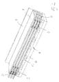
- Both separator members are provided with projecting ridges 23, which come into engagement with the glass plate, when stacked as depicted in Fig. 2 , where four glass plates and three sets of separator members have been stacked to form three stages. This means that there is a small space between the separator member and the glass plate.
- the top separator member is equipped with a sealing strip (not shown) sealing against the glass plate at its upper edge.
- a sealing ridge 24,34 which is present on the opposite side of both the top and bottom separator members comes into sealing engagement with the respective glass plates.
- the top separator 2 is provided with a foam strip 25 closing the space between the lower edge of the separator member and the glass plate.
- a foam strip 25 closing the space between the lower edge of the separator member and the glass plate.
- Both separator members has an offset section 27,37, which severs to separate the feed liquid from the condensate. At the top it keeps the feed fluid from rising too high, even if an excess of liquid has collected underneath the top separator member. At the bottom it keeps the residual fluid from entering the condensate collection tray 38 formed the bottom separator member.
- the separator members are identical except for the foam strip on the top member. This minimises the number of parts and thus decreases the overall cost of the module.
- the distance between the sheet members which is determined by the thickness of the separator members, should be as small as possible. If the distance, however, becomes too small the condensate could come into contact with the feed liquid, causing pollution of the condensate and a decrease in production. Experiments have shown, that the distance should be kept in the range of 5-10 mm, preferably 7-9 mm.
- the two separator member are shown more clearly in Fig. 4 and 5 .
- the glass sheets are arranged between two or more frame members 5, only one of which is visible in Fig. 2 .
- a tight module is formed. This may be achieved simply by wrapping straps around the assembly, but it is preferred to use brackets (not shown) or the like, possibly connected to a bottom element 6 underneath the stack of glass sheets, to achieve a more stable module.
- brackets not shown
- the assembly is simply unstrapped or the brackets loosened and damaged glass sheets may then easily be replaced.
- the frame members may for example be made from glass or melamine, which is capable of withstanding the elevated temperatures and humid conditions occurring in the module.
- Other materials such as ceramics may, however, also be used as may a surface coating of neoprene or the like.
- strip-like sealing member arranged between the glass plates or the two methods could be combined for achieving an even tighter construction.
- Both strip sealings and the frame members may contribute considerably to the stability of the module.
- Frame members may also be employed at the top and bottom of the module, but must of course allow for the introduction and extraction of the liquids.
- each stage constitutes an independent unit as regards the evaporation and condensation of liquid. Only heat is transferred from one stage to another.
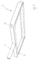
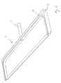
- a bottom member 6 which consists of a bottom plate 61 and a series of distance members 62. This bottom element may be seen more clearly in fig. 3 .
- the distance members shown serves two different purposes. Those 621, which are located at the edges of the bottom plate, serves to seal the space 63 between the glass and bottom plates from the ambient.
- the remaining distance members 622 are arranged in a manner resembling two intermeshing combs. Together they form a serpentine-like path stretching from an inlet opening 64 in the top-side distance member to an outlet opening 65 in the bottom-side distance member. When introducing a heating fluid trough the inlet 64 it will follow this path.
- a top element (not shown) corresponding in design to the bottom element in fig. 3 may be arranged on top of stack of stages, thereby closing the upper side of the module.
- the serpentine path will be used for passing a cooling fluid.
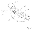
- the distillation module 100 described above is shown in combination with a solar collector 200 of the siphon type.
- a solar collector 200 of the siphon type When the sun hits the upper surface 201 of the solar collector the fluid within it will rise as indicated by the arrows a to reach the tank 202 at the top of the system. From there water will be pulled out under the influence of gravity as shown by the arrow b and a self circulating system will be established.
- the distillation module will be heated.
- the hot fluid may be passed through a serpentine-style bottom element as described above or any other suitable means may be employed.
- the fluid is then returned to the solar collector as indicated by the arrow d.
- Cooling of the distillation module 100 is achieved by letting the feed liquid coming from feed liquid source 101 as indicated by the arrow e pass over the upper side of the module as indicated by the arrow f before being taken back up an into the module as indicated by the arrow g. In this way the feed liquid is heated leading to an even better efficiency.
Landscapes
- Chemical & Material Sciences (AREA)
- Chemical Kinetics & Catalysis (AREA)
- Engineering & Computer Science (AREA)
- Life Sciences & Earth Sciences (AREA)
- Sustainable Energy (AREA)
- Sustainable Development (AREA)
- Environmental & Geological Engineering (AREA)
- Water Supply & Treatment (AREA)
- Hydrology & Water Resources (AREA)
- Organic Chemistry (AREA)
- Health & Medical Sciences (AREA)
- Toxicology (AREA)
- Vaporization, Distillation, Condensation, Sublimation, And Cold Traps (AREA)
- Heat Treatment Of Water, Waste Water Or Sewage (AREA)
Priority Applications (5)
| Application Number | Priority Date | Filing Date | Title |
|---|---|---|---|
| EP07123879A EP2072100A1 (fr) | 2007-12-20 | 2007-12-20 | Module de distillation incliné multi-effet doté de moyens de chauffage et de refroidissement |
| US12/809,834 US20100307910A1 (en) | 2007-12-20 | 2008-12-17 | Tilted multi effect distillation module with means for heating and cooling |
| BRPI0822096-4A BRPI0822096A2 (pt) | 2007-12-20 | 2008-12-17 | Módulo e sistema de destilação de multi efeito inclinado, e, método de aumentar a eficiência de um módulo de destilação de multi efeito inclinado |
| PCT/DK2008/000437 WO2009080029A1 (fr) | 2007-12-20 | 2008-12-17 | Module de distillation incliné à effet multiple doté de moyens de chauffage et de refroidissement |
| MX2010006962A MX2010006962A (es) | 2007-12-20 | 2008-12-17 | Un modulo de destilacion multiefecto inclinado con medios para calentamiento y enfriamiento. |
Applications Claiming Priority (1)
| Application Number | Priority Date | Filing Date | Title |
|---|---|---|---|
| EP07123879A EP2072100A1 (fr) | 2007-12-20 | 2007-12-20 | Module de distillation incliné multi-effet doté de moyens de chauffage et de refroidissement |
Publications (1)
| Publication Number | Publication Date |
|---|---|
| EP2072100A1 true EP2072100A1 (fr) | 2009-06-24 |
Family
ID=39529806
Family Applications (1)
| Application Number | Title | Priority Date | Filing Date |
|---|---|---|---|
| EP07123879A Withdrawn EP2072100A1 (fr) | 2007-12-20 | 2007-12-20 | Module de distillation incliné multi-effet doté de moyens de chauffage et de refroidissement |
Country Status (5)
| Country | Link |
|---|---|
| US (1) | US20100307910A1 (fr) |
| EP (1) | EP2072100A1 (fr) |
| BR (1) | BRPI0822096A2 (fr) |
| MX (1) | MX2010006962A (fr) |
| WO (1) | WO2009080029A1 (fr) |
Cited By (2)
| Publication number | Priority date | Publication date | Assignee | Title |
|---|---|---|---|---|
| WO2011098341A1 (fr) * | 2010-02-11 | 2011-08-18 | Vkr Holding A/S | Dispositif d'obtention d'eau douce à partir d'eau brute |
| ITRM20100516A1 (it) * | 2010-10-01 | 2012-04-02 | Fraunhofer Ges Forschung | Raffreddatore-concentratore evaporativo di salamoia |
Families Citing this family (6)
| Publication number | Priority date | Publication date | Assignee | Title |
|---|---|---|---|---|
| US10329167B2 (en) * | 2015-12-07 | 2019-06-25 | John L. CALENE | Compact high-efficiency solar distillation device |
| US10584042B2 (en) * | 2016-01-27 | 2020-03-10 | T.S.D. Desalination Ltd | Standalone humidification-dehumidification water purification method and system |
| US10874988B2 (en) * | 2016-05-23 | 2020-12-29 | Hsl Energy Holding Aps | Device for purifying liquids by distillation |
| US9968865B1 (en) * | 2017-08-25 | 2018-05-15 | Wei Wu | Multiple effect with vapor compression distillation apparatus |
| CN113233527A (zh) * | 2021-04-22 | 2021-08-10 | 重庆大学 | 一种z型结构多效蒸发式海水淡化系统 |
| US20250012481A1 (en) * | 2023-07-06 | 2025-01-09 | Midea Group Co., Ltd. | Separation plates, heat pump systems, and methods of filtering condensate |
Citations (8)
| Publication number | Priority date | Publication date | Assignee | Title |
|---|---|---|---|---|
| US4329204A (en) | 1980-02-19 | 1982-05-11 | Petrek John P | Multiple effect thin film distillation system |
| GB2123307A (en) * | 1979-03-22 | 1984-02-01 | Oriental Metal Seizo Co | Process and apparatus for the distillation of water |
| GB2123407A (en) | 1981-12-01 | 1984-02-01 | Ajinomoto Kk | Hydrazides and their use as latent curing agents for epoxy resins |
| AU2761384A (en) | 1984-05-02 | 1985-11-07 | Sri International | Concrete solar collector |
| EP0979801A1 (fr) | 1998-08-11 | 2000-02-16 | Communauté Européenne (CE) | Système pour la désalination de l'eau de mer par condensation d'air humide |
| WO2006002636A1 (fr) | 2004-07-06 | 2006-01-12 | Idekontoret Aps | Couche et module pour systeme de distillation a effet multiple |
| WO2009065407A2 (fr) | 2007-11-21 | 2009-05-28 | Idekontoret Aps | Collecteur solaire intégré et distillation à effets multiples |
| WO2009068029A1 (fr) | 2007-11-29 | 2009-06-04 | Idekontoret Aps | Dispositif modulaire de distillation d'eau |
-
2007
- 2007-12-20 EP EP07123879A patent/EP2072100A1/fr not_active Withdrawn
-
2008
- 2008-12-17 BR BRPI0822096-4A patent/BRPI0822096A2/pt not_active IP Right Cessation
- 2008-12-17 WO PCT/DK2008/000437 patent/WO2009080029A1/fr not_active Ceased
- 2008-12-17 MX MX2010006962A patent/MX2010006962A/es not_active Application Discontinuation
- 2008-12-17 US US12/809,834 patent/US20100307910A1/en not_active Abandoned
Patent Citations (9)
| Publication number | Priority date | Publication date | Assignee | Title |
|---|---|---|---|---|
| GB2123307A (en) * | 1979-03-22 | 1984-02-01 | Oriental Metal Seizo Co | Process and apparatus for the distillation of water |
| US4475988A (en) | 1979-03-22 | 1984-10-09 | Oriental Metal Mfg. Co., Ltd. | Process for distilling water and distillation apparatus |
| US4329204A (en) | 1980-02-19 | 1982-05-11 | Petrek John P | Multiple effect thin film distillation system |
| GB2123407A (en) | 1981-12-01 | 1984-02-01 | Ajinomoto Kk | Hydrazides and their use as latent curing agents for epoxy resins |
| AU2761384A (en) | 1984-05-02 | 1985-11-07 | Sri International | Concrete solar collector |
| EP0979801A1 (fr) | 1998-08-11 | 2000-02-16 | Communauté Européenne (CE) | Système pour la désalination de l'eau de mer par condensation d'air humide |
| WO2006002636A1 (fr) | 2004-07-06 | 2006-01-12 | Idekontoret Aps | Couche et module pour systeme de distillation a effet multiple |
| WO2009065407A2 (fr) | 2007-11-21 | 2009-05-28 | Idekontoret Aps | Collecteur solaire intégré et distillation à effets multiples |
| WO2009068029A1 (fr) | 2007-11-29 | 2009-06-04 | Idekontoret Aps | Dispositif modulaire de distillation d'eau |
Non-Patent Citations (2)
| Title |
|---|
| R.S ADHIKARI, A. KUMAR AND M.S. SODHA: "Thermal performance of a multi-effect diffusion solar still", INTERNATIONAL JOURNAL OF ENERGY RESEARCH, vol. 15, 1991, pages 769 - 779, XP002487218 * |
| R.S. ADHIKARI; A. KUMAR; M.S. SODHA: "Thermal performance of a multi-effect diffusion solar still", INTERNATIONAL JOURNAL OF ENERGY RESEARCH, vol. 15, 1991, pages 769 - 779 |
Cited By (3)
| Publication number | Priority date | Publication date | Assignee | Title |
|---|---|---|---|---|
| WO2011098341A1 (fr) * | 2010-02-11 | 2011-08-18 | Vkr Holding A/S | Dispositif d'obtention d'eau douce à partir d'eau brute |
| AT509426B1 (de) * | 2010-02-11 | 2012-01-15 | Vkr Holding As | Vorrichtung zur gewinnung von frischwasser aus rohwasser |
| ITRM20100516A1 (it) * | 2010-10-01 | 2012-04-02 | Fraunhofer Ges Forschung | Raffreddatore-concentratore evaporativo di salamoia |
Also Published As
| Publication number | Publication date |
|---|---|
| BRPI0822096A2 (pt) | 2015-06-30 |
| WO2009080029A1 (fr) | 2009-07-02 |
| US20100307910A1 (en) | 2010-12-09 |
| MX2010006962A (es) | 2010-10-26 |
Similar Documents
| Publication | Publication Date | Title |
|---|---|---|
| EP2072100A1 (fr) | Module de distillation incliné multi-effet doté de moyens de chauffage et de refroidissement | |
| US4235679A (en) | High performance solar still | |
| Santosh et al. | Performance evaluation and optimization of humidification–dehumidification desalination system for low-grade waste heat energy applications | |
| US9401676B2 (en) | Solar photovoltaic-thermal collector assembly and method of use | |
| Narayan et al. | The potential of solar-driven humidification–dehumidification desalination for small-scale decentralized water production | |
| CN109791000B (zh) | 具有空气热交换器的光伏热模块 | |
| US4257398A (en) | High efficiency solar collector | |
| EP3718147A1 (fr) | Améliorations apportées à des panneaux solaires et à l'accumulation d'énergie d'origine solaire | |
| WO2007127048A2 (fr) | Tour de refroidissement à point de rosée, échangeur de chaleur fixé par adhésif, et autres appareils de transfert de chaleur | |
| US9289696B2 (en) | Water desalination system using geothermal energy | |
| CN107176639A (zh) | 一种加湿冷凝式海水淡化装置 | |
| US7886537B2 (en) | Power generation system and associated methods | |
| US11067312B2 (en) | Solar energy system | |
| US20140360556A1 (en) | Methods and systems for temperature regulation of roof mounted and solar tracker mounted photovoltaic modules | |
| EP2219753A2 (fr) | Collecteur solaire intégré et distillation à effets multiples | |
| WO2013182916A1 (fr) | Collecteur solaire | |
| CA3182017A1 (fr) | Bac de base pour module thermique, module thermique comportant un tel bac de base, systeme d'extraction d'energie thermique et utilisation d'un tel bac de base pour l'extraction d'energie thermique a partir de la lumiere solair | |
| US20100294644A1 (en) | Heat exchanger | |
| WO2014004718A2 (fr) | Système de dessalement ou de distillation compact avec échangeur de chaleur à spirales intégré | |
| GB2441827A (en) | Desalination plant | |
| KR102811485B1 (ko) | 태양광열 집열 장치 | |
| FR2896495A1 (fr) | Distillateur d'eau de mer a plaques continues et etagement de pression | |
| CN208832757U (zh) | 一种弧形开口板芯太阳能空气集热器 | |
| WO2023017273A1 (fr) | Capteur thermique solaire | |
| FR3005813A1 (fr) | Panneau solaire hybride |
Legal Events
| Date | Code | Title | Description |
|---|---|---|---|
| PUAI | Public reference made under article 153(3) epc to a published international application that has entered the european phase |
Free format text: ORIGINAL CODE: 0009012 |
|
| AK | Designated contracting states |
Kind code of ref document: A1 Designated state(s): AT BE BG CH CY CZ DE DK EE ES FI FR GB GR HU IE IS IT LI LT LU LV MC MT NL PL PT RO SE SI SK TR |
|
| AX | Request for extension of the european patent |
Extension state: AL BA HR MK RS |
|
| 17P | Request for examination filed |
Effective date: 20091208 |
|
| 17Q | First examination report despatched |
Effective date: 20100202 |
|
| AKX | Designation fees paid |
Designated state(s): AT BE BG CH CY CZ DE DK EE ES FI FR GB GR HU IE IS IT LI LT LU LV MC MT NL PL PT RO SE SI SK TR |
|
| TPAC | Observations filed by third parties |
Free format text: ORIGINAL CODE: EPIDOSNTIPA |
|
| STAA | Information on the status of an ep patent application or granted ep patent |
Free format text: STATUS: THE APPLICATION IS DEEMED TO BE WITHDRAWN |
|
| 18D | Application deemed to be withdrawn |
Effective date: 20120417 |