EP2072193A2 - codeur mécanique disposé entre un bloc-batterie et un outil électrique - Google Patents
codeur mécanique disposé entre un bloc-batterie et un outil électrique Download PDFInfo
- Publication number
- EP2072193A2 EP2072193A2 EP09100202A EP09100202A EP2072193A2 EP 2072193 A2 EP2072193 A2 EP 2072193A2 EP 09100202 A EP09100202 A EP 09100202A EP 09100202 A EP09100202 A EP 09100202A EP 2072193 A2 EP2072193 A2 EP 2072193A2
- Authority
- EP
- European Patent Office
- Prior art keywords
- battery pack
- coding
- recess
- pack according
- power tool
- Prior art date
- Legal status (The legal status is an assumption and is not a legal conclusion. Google has not performed a legal analysis and makes no representation as to the accuracy of the status listed.)
- Granted
Links
Images


Classifications
-
- H—ELECTRICITY
- H01—ELECTRIC ELEMENTS
- H01M—PROCESSES OR MEANS, e.g. BATTERIES, FOR THE DIRECT CONVERSION OF CHEMICAL ENERGY INTO ELECTRICAL ENERGY
- H01M50/00—Constructional details or processes of manufacture of the non-active parts of electrochemical cells other than fuel cells, e.g. hybrid cells
- H01M50/20—Mountings; Secondary casings or frames; Racks, modules or packs; Suspension devices; Shock absorbers; Transport or carrying devices; Holders
- H01M50/204—Racks, modules or packs for multiple batteries or multiple cells
- H01M50/207—Racks, modules or packs for multiple batteries or multiple cells characterised by their shape
- H01M50/213—Racks, modules or packs for multiple batteries or multiple cells characterised by their shape adapted for cells having curved cross-section, e.g. round or elliptic
-
- B—PERFORMING OPERATIONS; TRANSPORTING
- B25—HAND TOOLS; PORTABLE POWER-DRIVEN TOOLS; MANIPULATORS
- B25F—COMBINATION OR MULTI-PURPOSE TOOLS NOT OTHERWISE PROVIDED FOR; DETAILS OR COMPONENTS OF PORTABLE POWER-DRIVEN TOOLS NOT PARTICULARLY RELATED TO THE OPERATIONS PERFORMED AND NOT OTHERWISE PROVIDED FOR
- B25F5/00—Details or components of portable power-driven tools not particularly related to the operations performed and not otherwise provided for
- B25F5/02—Construction of casings, bodies or handles
-
- Y—GENERAL TAGGING OF NEW TECHNOLOGICAL DEVELOPMENTS; GENERAL TAGGING OF CROSS-SECTIONAL TECHNOLOGIES SPANNING OVER SEVERAL SECTIONS OF THE IPC; TECHNICAL SUBJECTS COVERED BY FORMER USPC CROSS-REFERENCE ART COLLECTIONS [XRACs] AND DIGESTS
- Y02—TECHNOLOGIES OR APPLICATIONS FOR MITIGATION OR ADAPTATION AGAINST CLIMATE CHANGE
- Y02E—REDUCTION OF GREENHOUSE GAS [GHG] EMISSIONS, RELATED TO ENERGY GENERATION, TRANSMISSION OR DISTRIBUTION
- Y02E60/00—Enabling technologies; Technologies with a potential or indirect contribution to GHG emissions mitigation
- Y02E60/10—Energy storage using batteries
Definitions
- the invention relates to a plug-in battery pack for a power tool, with a mechanical coding of a coding system for cooperation with a power tool associated, mechanical counter-coding of the coding system, wherein the coding extends in the insertion direction of the battery pack.
- battery pack is to be understood as an accumulator packet preferably consisting of several cells, which supplies the power for the operation of the power tool and is exchangeably received in a chamber or the like of the power tool.
- the assignment of the battery pack to the power tool by inserting or inserting. If the energy of the battery pack is used up, it can be removed and fed to a charging station. If several battery packs are available, it is possible to remove the discharged battery pack from the power tool and replace it with a charged one. In order to prevent an incorrect battery pack from being assigned to the power tool during an exchange or a reassignment, which could occur in particular, if several different battery packs are available for different electrical devices, a secure and essentially non-manipulatable coding system is required. Also, such a coding system is to exclude inadmissible battery packs that should not be assigned to the power tool.
- the coding has at least one with at least one tool-side, the counter-coding projection on opposite sides cooperating recess which in the region Contact dome of the battery pack is arranged.
- This contact dome carries the one hand, the coding and on the other hand, the electrical contact elements to produce an electrical connection from the battery pack to the power tool by inserting the battery pack in the power tool.
- the counter-coding associated with the power tool consists of at least one projection, the battery pack having at least one corresponding recess, opposite sides of the recess cooperating with the projection upon insertion of the battery pack into the power tool.
- the recess has at least two mutually the thickness of the projection corresponding opposite wall surface areas. Between these two wall surface areas occurs in the assignment of the battery pack to the power tool, the projection, that is, the two wall surface areas take the lead between them leader. It is thus clear that a lateral bending of the projection would lead to a blockage, so that the insertion movement of the battery pack is stopped and even larger forces can not overcome this stop.
- the depression is a circumferentially closed depression.
- This is to be understood as a depression whose depression edge describes a self-contained loop-shaped line.
- the recess it is also possible for the recess to be an open-edged recess, that is to say it is accessible from the side through at least one opening, that is to say that its edge is not a self-contained loop-shaped line but forms, for example, an open one U.
- the depression has a triangular, polygonal, arcuate and / or circular ground plan structure.
- the corresponding floor plan structure is corresponding to the projection available, so that a one-to-one assignment of projection to recess is possible. As a result, rotational positions between the battery pack and the power tool are excluded.
- the recess is preferably formed as a cylindrical recess, that is, their wall surfaces are parallel to each other. They do not taper down to the bottom of the well, but run parallel to the insertion direction.
- the term "cylindrical” is accordingly to be understood as meaning that a line running from the recess edge to the recess bottom is displaced parallel to it along any curve, closed or not closed, defining the cylinder contour, so that the recess opposite the plug has no inclined surfaces or wall sections or the like.
- a development of the invention provides that the depression is arranged in the vicinity of electrical contacts of the battery pack. This is advantageous because then in the vicinity of the electrical contacts, the blocking effect of non-matching coding elements is exercised and thereby securely contacting the battery pack is prevented with the corresponding terminals of the power tool.
- the depression is arranged between at least two electrical contacts of the battery pack. This also leads to the advantages mentioned above.
- the recess and / or the contact dome is arranged eccentrically to the base center of the battery pack, so that rotational positions are excluded and accordingly the battery pack can be supplied to the power tool only in a single position.
- At least one coding rib is provided from the wall of the recess emanates.
- the coding rib leads, in addition to the coding unit already formed by the projection and the depression, to a further refined coding measure. This is especially the case when the coding rib emanates from the wall of the depression to form different permutations at a position determined by a plurality of different positions.
- a further development of the invention provides that at least one pair of coding ribs originates from the wall of the recess, the coding ribs of which face one another in such a way that they overlap at least partially.
- a Kodierrippenform consists of two Kodierrippen, which are spaced apart from each other in such a way that can thread between their end faces of the projection upon insertion of the battery pack in the power tool.
- the two Kodierrippen - transverse to the insertion direction - aligned with each other so are the same width and in alignment with each other (aligned end faces), but it can also be used coding ribs that do not have the same width and a Form coding rib pair and / or offset from each other, but the offset is not so large that between them creates a lateral space, but the end surfaces overlap at least partially.
- a further development of the invention provides that at least one outer wall surface opposite a region of the projection adjoins the open-edged recess. Accordingly, at least one region lying outside the open-edged recess is also used for the coding system, in that the projection not only extends in the open-edged recess, but also penetrates into the lateral opening of the recess and to an outer wall surface located there adjacent to the recess , in opposition occurs. This increases the permutation diversity and also increases the security of the permutation system due to larger-area element designs.
- the invention relates to a coding system for a power pack provided with a retractable battery pack, in particular according to one or more of the preceding embodiments, wherein the battery pack has a mechanical coding and the power tool has a mechanical counter coding and coding and counter coding extend in the insertion direction, the coding being at least one depression and the counter coding being at least one projection is formed and coding and Jacobkodtechnik are matched to match shape and engage each other with inserted battery pack. It is provided in particular that the projection cooperates with opposite sides of the recess.
- FIG. 1 shows a section of a plug-in battery pack 1 for a power tool, not shown.
- the battery pack 1 has a handle 2, on which it can be held by the user, for example, to take him from a charger and plug with a plug-in area 3 in the insertion direction 4 in a power tool.
- the insertion region 3 has an end face 6 which forms a base 8 and extends perpendicular to the insertion direction 4.
- On the end face 6, a contact dome 7 is arranged on the end face 6, a contact dome 7 is arranged. This contact dome 7 is arranged eccentrically with respect to the base center 8 'of the battery pack 1.
- the contact dome 7 extends substantially in the direction of insertion 4.
- the contact dome 7 has an upper side 9, which has an end face 10 which runs parallel to the end face 6, ie perpendicular to the insertion direction 4, and oblique surfaces 11.
- the contact dome 7 has side faces 12, which are perpendicular to the end face 6 and the end face 10.
- two contact openings 13 and 14 are formed, in which electrical contacts 15 are arranged.
- the contact dome 7 also has a mechanical coding 16, which together with a in FIG. 1 not shown counter coding of the power tool forms a coding system 30. At the countercoding is at the essay of the FIG. 2 received.
- the mechanical coding 16 of the battery pack 1 has a recess 17.
- the recess 17 has a rectangular base 31, which forms a recess bottom 32 of the recess 17.
- the recess 17 has a wall 18 which is composed of wall surface areas 19, 20 and 21.
- the wall 18 extends parallel to the insertion direction 4.
- the wall surface portions 19 and 20 are parallel to each other.
- the wall surface region 21 extends in each case at right angles to the wall surface regions 19 and 20.
- the side surface of the depression 17 opposite the wall surface region 21 is open-edged, that is, the depression 17 opens into an outer wall surface 22 which forms one of the side surfaces 12 of the contact dome 7.
- the FIG. 1 can be seen that emanate from the two, opposing wall surface portions 19 and 20 coding ribs 23 and 24, which face each other in alignment with spaced-apart end faces 26. This means that between the end faces 26, a gap 27 is formed.
- the coding ribs 23 and 24 effect a refined coding measure of the depression 17.
- the depression 17 is arranged at least in regions between the contacts 15. From the outer wall surface 22 is a rib 28, which is also part of the coding system 30, so the coding 16 belongs. Alternatively, it is also possible that such a rib 28 is not present (not shown).
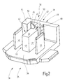
- FIG. 2 shows a portion 35 of an otherwise not shown power tool 36, in which the battery pack 1 can be inserted.
- the insertion shaft, which accommodates the battery pack 1, is in FIG. 2 not shown.
- the section 35 of the power tool 36 has two contact tongues 37, which cooperate with the contacts 15 in the inserted state of the battery pack 1.
- the two contact tongues 37 start from a ground plane 38 of the power tool 36, on which a counter-coding 39 of the coding system 30 is further arranged.
- the counter-coding 39 interacts with the coding 16 in such a way that the coincidence of the coding 16 and the counter-coding 39 makes it possible to introduce the battery pack.
- the counter-coding 39 has a projection 40, which has two mutually opposite wall surfaces 41 and 42 as well as an end face 43 and a head face 44. Further, the projection 40 has a waist 45, which is formed due to two cuts 46 and 47 in the wall surfaces 41 and 42.
- the distance between the two wall surfaces 41 and 42 corresponds - taking into account a very small clearance - the distance of the wall surface portions 19 and 20 of the recess 17.
- the incisions 46 and 47 correspond in their dimensions to the contours of the two Kodierrippen 23 and 24, wherein also a slight play is considered.
- the arrangement is further made such that the region 48 of the projection 40 beyond the waist 45 comes to lie next to the rib 28 of the coding 16 when the coding 16 and counter-coding 39 are brought together.
- the projection 40 is adjoined by an L-shaped wall region 49, which has a leg 50 and a transverse leg 51. Between the transverse leg 51, the leg 50 and the region 48 of the projection 40, a recess 52 is formed, the dimensions of which, taking account of a certain amount of play, correspond to the dimensions of the rib 28 of the coding 16.
- a battery pack 1 is used whose coding 16 is not formed to match the counter-coding 39 of the power tool 36 because, for example, the distance between the two wall surface areas 19 and 20 is smaller than the distance of the wall surfaces 41 and 42 of the projection 40, this is known from the prior art "overpressure" not possible, that is, projection 40 and recess 17 can not, even with very large Kraftaufprocess- not put together, because a lateral deflection of the projection 40 is therefore not possible because the top surface 44 of the projection 40 would fit on the recess edge portion 53 of the coding 16 and therefore blocks further insertion.
- the two coding ribs 23 and 24 emanate from a coding rib pair 55 at correspondingly different positions from the wall 18 of the recess 17.
- the two Kodierrippen 23 and 24 opposite to that of the FIG. 1 emerge position closer to the wall surface portion 21 of the recess 17 lying.
- corresponding grid spacings for the different positions of the coding rib pair 55 can be provided.
- the two Kodierrippen 23 and 24 -anders than in the FIG. 1 - Are not in alignment with each other, but are so slightly offset from one another that their two end faces 26 only partially face each other.
- further coding ribs or further coding rib pairs are provided. Accordingly, then the structure of the projection is designed.
- FIG. 3 shows an embodiment in which, for example, the projection 40 has three waists 45, that is, since the counter-coding 39 is provided with three cuts 46 and three cuts 47, the form fitting thereto designed, not shown coding 16 will have three Kodierrippenschreib 55. From all of this it is clear that the coding system 30 thus created allows a very large number of permutations.
Landscapes
- Chemical & Material Sciences (AREA)
- Chemical Kinetics & Catalysis (AREA)
- Electrochemistry (AREA)
- General Chemical & Material Sciences (AREA)
- Engineering & Computer Science (AREA)
- Mechanical Engineering (AREA)
- Battery Mounting, Suspending (AREA)
Applications Claiming Priority (2)
| Application Number | Priority Date | Filing Date | Title |
|---|---|---|---|
| DE102005008036.7A DE102005008036B4 (de) | 2005-02-22 | 2005-02-22 | Einsteckbarer Batteriepack, Elektrowerkzeug und Kodiersystem |
| EP06701217A EP1855844B8 (fr) | 2005-02-22 | 2006-01-03 | Codeur mecanique dispose entre un bloc-batterie et un outil electrique |
Related Parent Applications (1)
| Application Number | Title | Priority Date | Filing Date |
|---|---|---|---|
| EP06701217A Division EP1855844B8 (fr) | 2005-02-22 | 2006-01-03 | Codeur mecanique dispose entre un bloc-batterie et un outil electrique |
Publications (3)
| Publication Number | Publication Date |
|---|---|
| EP2072193A2 true EP2072193A2 (fr) | 2009-06-24 |
| EP2072193A3 EP2072193A3 (fr) | 2009-07-01 |
| EP2072193B1 EP2072193B1 (fr) | 2017-04-12 |
Family
ID=36177331
Family Applications (3)
| Application Number | Title | Priority Date | Filing Date |
|---|---|---|---|
| EP09100202.2A Expired - Lifetime EP2072193B1 (fr) | 2005-02-22 | 2006-01-03 | codeur mécanique disposé entre un bloc-batterie et un outil électrique |
| EP06701217A Ceased EP1855844B8 (fr) | 2005-02-22 | 2006-01-03 | Codeur mecanique dispose entre un bloc-batterie et un outil electrique |
| EP10168058.5A Ceased EP2338648B1 (fr) | 2005-02-22 | 2006-01-03 | Codage mécanique entre une batterie et un outil électrique |
Family Applications After (2)
| Application Number | Title | Priority Date | Filing Date |
|---|---|---|---|
| EP06701217A Ceased EP1855844B8 (fr) | 2005-02-22 | 2006-01-03 | Codeur mecanique dispose entre un bloc-batterie et un outil electrique |
| EP10168058.5A Ceased EP2338648B1 (fr) | 2005-02-22 | 2006-01-03 | Codage mécanique entre une batterie et un outil électrique |
Country Status (5)
| Country | Link |
|---|---|
| US (2) | US7588471B2 (fr) |
| EP (3) | EP2072193B1 (fr) |
| CN (2) | CN102218728B (fr) |
| DE (3) | DE202005021711U1 (fr) |
| WO (1) | WO2006089810A1 (fr) |
Cited By (1)
| Publication number | Priority date | Publication date | Assignee | Title |
|---|---|---|---|---|
| US9605621B2 (en) | 2012-11-08 | 2017-03-28 | Rolls-Royce Deutschland Ltd & Co Kg | Nozzle with guiding devices |
Families Citing this family (23)
| Publication number | Priority date | Publication date | Assignee | Title |
|---|---|---|---|---|
| US7443137B2 (en) | 2000-08-11 | 2008-10-28 | Milwaukee Electric Tool Corporation | Adapter for a power tool battery |
| US7799448B2 (en) * | 2007-06-19 | 2010-09-21 | Black & Decker Inc. | Battery pack for cordless devices |
| JP2009083089A (ja) | 2007-09-14 | 2009-04-23 | Makita Corp | 手持ち式電動工具のハンドル部 |
| DE102007044501A1 (de) * | 2007-09-18 | 2009-03-19 | Robert Bosch Gmbh | Akkupack und Elektrogerät |
| US8591242B2 (en) * | 2010-04-08 | 2013-11-26 | Illinois Tool Works Inc. | Floating battery contact module for a power tool |
| US9461281B2 (en) | 2010-10-08 | 2016-10-04 | Milwaukee Electric Tool Corporation | Battery retention system for a power tool |
| DE102011007860A1 (de) * | 2011-04-21 | 2012-10-25 | Siemens Aktiengesellschaft | Messvorrichtung, Ladevorrichtung, sowie eine Magnetresonanzvorrichtung mit einer Messvorrichtung und ein Aufladeverfahren hierzu |
| US8979110B2 (en) * | 2012-03-16 | 2015-03-17 | Specialized Bicycle Components, Inc. | Bicycle with battery mount |
| DE102012209919A1 (de) * | 2012-06-13 | 2013-12-19 | Hilti Aktiengesellschaft | Handwerkzeugmaschine |
| USD730287S1 (en) | 2013-12-31 | 2015-05-26 | Sony Corporation | Rechargeable battery |
| USD740222S1 (en) * | 2014-04-11 | 2015-10-06 | SZ DJI Technology Co., Ltd. | Chargeable battery |
| US9608245B2 (en) | 2014-09-30 | 2017-03-28 | Johnson Controls Technology Company | System for providing structural integrity of a battery module |
| KR102273646B1 (ko) | 2014-10-27 | 2021-07-06 | 삼성에스디아이 주식회사 | 에너지 저장 장치 및 그 트레이에 식별부호를 설정하는 방법 |
| US10363614B2 (en) | 2015-04-02 | 2019-07-30 | Stanley Black & Decker Inc. | Laser level, battery pack and system |
| USD817266S1 (en) | 2016-01-26 | 2018-05-08 | SZ DJI Technology Co., Ltd. | Battery |
| US10381041B2 (en) * | 2016-02-16 | 2019-08-13 | Shimmeo, Inc. | System and method for automated video editing |
| CN107799681B (zh) * | 2016-09-01 | 2022-07-12 | 康塔有限公司 | 可再充电电池组 |
| DE102017217495A1 (de) * | 2017-09-29 | 2019-04-04 | Robert Bosch Gmbh | Akkupack |
| USD921575S1 (en) | 2018-06-26 | 2021-06-08 | SZ DJI Technology Co., Ltd. | Battery |
| USD937760S1 (en) | 2019-06-12 | 2021-12-07 | Techtronic Cordless Gp | Terminal block of a battery pack |
| USD937759S1 (en) | 2019-06-12 | 2021-12-07 | Techtronic Cordless Gp | Terminal block of a battery pack |
| US11670819B2 (en) | 2019-08-09 | 2023-06-06 | Techtronic Cordless Gp | Battery pack including staggered battery pack terminals |
| WO2021190612A1 (fr) | 2020-03-26 | 2021-09-30 | 格力博(江苏)股份有限公司 | Véhicule électrique et système de batterie |
Citations (1)
| Publication number | Priority date | Publication date | Assignee | Title |
|---|---|---|---|---|
| US6551123B1 (en) | 1995-02-10 | 2003-04-22 | Marquardt Gmbh | Guiding arrangement for a plug-in battery pack operating an electric appliance |
Family Cites Families (5)
| Publication number | Priority date | Publication date | Assignee | Title |
|---|---|---|---|---|
| DE4402355C2 (de) * | 1994-01-27 | 1997-02-13 | Metabowerke Kg | Schnurloses Elektrohandwerkzeug |
| US6296065B1 (en) * | 1998-12-30 | 2001-10-02 | Black & Decker Inc. | Dual-mode non-isolated corded system for transportable cordless power tools |
| JP2002543564A (ja) * | 1999-04-23 | 2002-12-17 | コーニンクレッカ フィリップス エレクトロニクス エヌ ヴィ | バッテリホルダを備えた電気機器 |
| SG97837A1 (en) * | 2000-01-25 | 2003-08-20 | Molex Inc | Electrical connector with molded plastic housing |
| US6790067B2 (en) * | 2002-12-17 | 2004-09-14 | Tyco Electronics Corporation | Finger proof power connector |
-
2005
- 2005-02-22 DE DE202005021711U patent/DE202005021711U1/de not_active Expired - Lifetime
- 2005-02-22 DE DE102005008036.7A patent/DE102005008036B4/de not_active Expired - Lifetime
-
2006
- 2006-01-03 CN CN2011101285758A patent/CN102218728B/zh not_active Expired - Fee Related
- 2006-01-03 EP EP09100202.2A patent/EP2072193B1/fr not_active Expired - Lifetime
- 2006-01-03 DE DE502006008179T patent/DE502006008179D1/de not_active Expired - Lifetime
- 2006-01-03 WO PCT/EP2006/050008 patent/WO2006089810A1/fr not_active Ceased
- 2006-01-03 US US11/718,866 patent/US7588471B2/en not_active Expired - Lifetime
- 2006-01-03 CN CN2006800057319A patent/CN101128287B/zh not_active Expired - Fee Related
- 2006-01-03 EP EP06701217A patent/EP1855844B8/fr not_active Ceased
- 2006-01-03 EP EP10168058.5A patent/EP2338648B1/fr not_active Ceased
-
2009
- 2009-04-23 US US12/428,890 patent/US7648402B2/en active Active
Patent Citations (1)
| Publication number | Priority date | Publication date | Assignee | Title |
|---|---|---|---|---|
| US6551123B1 (en) | 1995-02-10 | 2003-04-22 | Marquardt Gmbh | Guiding arrangement for a plug-in battery pack operating an electric appliance |
Cited By (1)
| Publication number | Priority date | Publication date | Assignee | Title |
|---|---|---|---|---|
| US9605621B2 (en) | 2012-11-08 | 2017-03-28 | Rolls-Royce Deutschland Ltd & Co Kg | Nozzle with guiding devices |
Also Published As
| Publication number | Publication date |
|---|---|
| CN101128287A (zh) | 2008-02-20 |
| EP2338648A2 (fr) | 2011-06-29 |
| WO2006089810A1 (fr) | 2006-08-31 |
| DE102005008036B4 (de) | 2014-01-09 |
| EP1855844B8 (fr) | 2011-02-02 |
| DE102005008036A1 (de) | 2006-08-24 |
| US20080003494A1 (en) | 2008-01-03 |
| EP2072193A3 (fr) | 2009-07-01 |
| US7648402B2 (en) | 2010-01-19 |
| EP1855844B1 (fr) | 2010-10-27 |
| EP2338648B1 (fr) | 2015-09-02 |
| CN101128287B (zh) | 2011-11-16 |
| CN102218728B (zh) | 2013-10-23 |
| EP2072193B1 (fr) | 2017-04-12 |
| EP1855844A1 (fr) | 2007-11-21 |
| EP2338648A3 (fr) | 2011-07-27 |
| US7588471B2 (en) | 2009-09-15 |
| DE202005021711U1 (de) | 2009-08-13 |
| DE502006008179D1 (de) | 2010-12-09 |
| CN102218728A (zh) | 2011-10-19 |
| US20090202896A1 (en) | 2009-08-13 |
Similar Documents
| Publication | Publication Date | Title |
|---|---|---|
| EP2338648B1 (fr) | Codage mécanique entre une batterie et un outil électrique | |
| DE4131768B4 (de) | Elektrischer Verbinder mit Doppelverriegelung | |
| DE69510248T2 (de) | Nockenbetätigter Verbinder | |
| DE69923051T2 (de) | Verriegelbarer elektrischer Steckverbinder | |
| DE69205511T2 (de) | Elektrischer steckverbinder mit abgedichteter drahtdurchführung. | |
| DE102009004849B4 (de) | Verbinder und Montageverfahren | |
| EP3316421A1 (fr) | Adaptateur compact de prise de courant de voyage pouvant être mis à la terre | |
| DE102009004845B4 (de) | Verbinder und Montageverfahren für diesen | |
| EP0847604A1 (fr) | Connecteur electrique pourvu d'un coulisseau de stabilisation du contact | |
| AT409995B (de) | Schlüssel für zylinderschloss | |
| DE212018000283U1 (de) | gerade zusammengebauter Block, der einfach gekoppelt und verschleißfest ist | |
| EP2743949B1 (fr) | Dispositif de coupure de courant avec mécanisme de verrouillage | |
| EP2203947B1 (fr) | Bloc d'accumulateur et appareil électrique avec des moyens de codage tridimensionnels | |
| EP3092359B1 (fr) | Serrure à cylindre | |
| EP0018940A1 (fr) | Appareil radio-électrique portable dont la partie batterie peut-être separée de la partie émetteur-récepteur | |
| DE102005063606B3 (de) | Mechanische Kodierung zwischen Batteriepack und Elektrowerkzeug | |
| EP0627130B1 (fr) | Connecteur enfichable | |
| DE19541805A1 (de) | Elektrischer Verbinder | |
| DE10243313B4 (de) | Kodierbarer Steckverbinder | |
| DE19956031A1 (de) | Steckdose | |
| DE2719841B2 (de) | Mehrpolige Steckvorrichtung für Schwachstromanlagen, insbesondere Telefonanlagen | |
| DE3404482C2 (fr) | ||
| WO2009071256A1 (fr) | Prise femelle pour appareil chirurgical hf | |
| AT406884B (de) | Schliesszylinder | |
| DE19543497A1 (de) | Elektrischer Verbinder |
Legal Events
| Date | Code | Title | Description |
|---|---|---|---|
| PUAI | Public reference made under article 153(3) epc to a published international application that has entered the european phase |
Free format text: ORIGINAL CODE: 0009012 |
|
| PUAL | Search report despatched |
Free format text: ORIGINAL CODE: 0009013 |
|
| AC | Divisional application: reference to earlier application |
Ref document number: 1855844 Country of ref document: EP Kind code of ref document: P |
|
| AK | Designated contracting states |
Kind code of ref document: A2 Designated state(s): FR GB |
|
| AK | Designated contracting states |
Kind code of ref document: A3 Designated state(s): FR GB |
|
| 17P | Request for examination filed |
Effective date: 20100104 |
|
| AKX | Designation fees paid |
Designated state(s): FR GB |
|
| 17Q | First examination report despatched |
Effective date: 20100308 |
|
| GRAP | Despatch of communication of intention to grant a patent |
Free format text: ORIGINAL CODE: EPIDOSNIGR1 |
|
| RIC1 | Information provided on ipc code assigned before grant |
Ipc: B25F 5/02 20060101ALI20161206BHEP Ipc: H01M 2/10 20060101AFI20161206BHEP |
|
| INTG | Intention to grant announced |
Effective date: 20170105 |
|
| GRAS | Grant fee paid |
Free format text: ORIGINAL CODE: EPIDOSNIGR3 |
|
| GRAA | (expected) grant |
Free format text: ORIGINAL CODE: 0009210 |
|
| AC | Divisional application: reference to earlier application |
Ref document number: 1855844 Country of ref document: EP Kind code of ref document: P |
|
| AK | Designated contracting states |
Kind code of ref document: B1 Designated state(s): FR GB |
|
| REG | Reference to a national code |
Ref country code: GB Ref legal event code: FG4D Free format text: NOT ENGLISH |
|
| REG | Reference to a national code |
Ref country code: FR Ref legal event code: PLFP Year of fee payment: 13 |
|
| PLBE | No opposition filed within time limit |
Free format text: ORIGINAL CODE: 0009261 |
|
| STAA | Information on the status of an ep patent application or granted ep patent |
Free format text: STATUS: NO OPPOSITION FILED WITHIN TIME LIMIT |
|
| 26N | No opposition filed |
Effective date: 20180115 |
|
| P01 | Opt-out of the competence of the unified patent court (upc) registered |
Effective date: 20230509 |
|
| PGFP | Annual fee paid to national office [announced via postgrant information from national office to epo] |
Ref country code: FR Payment date: 20250128 Year of fee payment: 20 |
|
| PGFP | Annual fee paid to national office [announced via postgrant information from national office to epo] |
Ref country code: GB Payment date: 20250123 Year of fee payment: 20 |
|
| REG | Reference to a national code |
Ref country code: GB Ref legal event code: PE20 Expiry date: 20260102 |