EP2072254A2 - Cylindre de transport doté d'un dispositif de préhension mobile - Google Patents
Cylindre de transport doté d'un dispositif de préhension mobile Download PDFInfo
- Publication number
- EP2072254A2 EP2072254A2 EP08021511A EP08021511A EP2072254A2 EP 2072254 A2 EP2072254 A2 EP 2072254A2 EP 08021511 A EP08021511 A EP 08021511A EP 08021511 A EP08021511 A EP 08021511A EP 2072254 A2 EP2072254 A2 EP 2072254A2
- Authority
- EP
- European Patent Office
- Prior art keywords
- transport cylinder
- gripper
- gripper device
- sheet
- rotation
- Prior art date
- Legal status (The legal status is an assumption and is not a legal conclusion. Google has not performed a legal analysis and makes no representation as to the accuracy of the status listed.)
- Withdrawn
Links
- 238000007639 printing Methods 0.000 claims abstract description 79
- 238000000034 method Methods 0.000 claims abstract description 13
- 230000006835 compression Effects 0.000 claims description 3
- 238000007906 compression Methods 0.000 claims description 3
- 230000009471 action Effects 0.000 claims description 2
- 239000011248 coating agent Substances 0.000 abstract description 8
- 238000000576 coating method Methods 0.000 abstract description 8
- 238000011144 upstream manufacturing Methods 0.000 description 8
- 239000003973 paint Substances 0.000 description 6
- 239000000463 material Substances 0.000 description 4
- 230000002093 peripheral effect Effects 0.000 description 4
- 239000000758 substrate Substances 0.000 description 4
- 238000005096 rolling process Methods 0.000 description 3
- 230000008859 change Effects 0.000 description 2
- 238000006073 displacement reaction Methods 0.000 description 2
- 239000000976 ink Substances 0.000 description 2
- 238000010422 painting Methods 0.000 description 2
- 230000001681 protective effect Effects 0.000 description 2
- 238000005452 bending Methods 0.000 description 1
- 230000015572 biosynthetic process Effects 0.000 description 1
- 238000004040 coloring Methods 0.000 description 1
- 230000003750 conditioning effect Effects 0.000 description 1
- 230000001419 dependent effect Effects 0.000 description 1
- 238000007646 gravure printing Methods 0.000 description 1
- 230000000977 initiatory effect Effects 0.000 description 1
- 230000007246 mechanism Effects 0.000 description 1
- 238000007645 offset printing Methods 0.000 description 1
- 230000008569 process Effects 0.000 description 1
- 230000004044 response Effects 0.000 description 1
- 230000000284 resting effect Effects 0.000 description 1
- 238000000926 separation method Methods 0.000 description 1
- 239000002966 varnish Substances 0.000 description 1
Images


Classifications
-
- B—PERFORMING OPERATIONS; TRANSPORTING
- B41—PRINTING; LINING MACHINES; TYPEWRITERS; STAMPS
- B41F—PRINTING MACHINES OR PRESSES
- B41F21/00—Devices for conveying sheets through printing apparatus or machines
- B41F21/10—Combinations of transfer drums and grippers
- B41F21/104—Gripper details
Definitions
- the invention relates to a transport cylinder for transporting sheets in a printing or coating machine comprising at least one gripper device for gripping and holding the leading edge of a sheet to be transported, which is arranged in at least one recess of the transport cylinder and rotates with the transport cylinder about its axis of rotation.
- the invention further relates to a method for transporting sheets in a printing or coating machine in which at least one gripper device, the leading edge of a sheet to be transported is gripped and held, wherein the gripper device is arranged in at least one recess of a transport cylinder and with the transport cylinder to the Rotation axis rotates.
- Printing machines and varnishing machines for printing or varnishing sheet-shaped substrates have been used industrially for many years. Since the object of the invention can be used both in printing presses and in varnishing machines, therefore, all subsequent descriptions relate both to printing presses and to varnishing machines without limiting the general public.
- One type of printing presses operates according to a rotary printing principle, such as flexographic printing, offset printing, high-pressure, gravure printing, etc., in which the printing original of the image to be printed is introduced in a lateral surface of one or more printing cylinders or clamped as a printing plate on the lateral surface of a printing cylinder and during the Printing process via an unwinding of the printing cylinder over its lateral surface, the print image is transmitted either directly or via downstream transfer cylinder on the substrate.
- the printing original located on the printing cylinder is inked with one or more inking rollers so that at each revolution of the printing cylinder uniform coloring of the ink-transferring areas of the print template over the entire print image, which ensures that a substantially constant print quality results in the substrate.
- the printing of sheet-shaped substrates it is further provided to remove the sheets to be printed continuously in an automatic manner before printing from a supply stack and feed the printing unit to remove the sheets after their printing back from the printing unit, the applied ink optionally then to dry and place the sheets on a stack of output.
- the applied ink optionally then to dry and place the sheets on a stack of output.
- the sheets to be printed by means of a first gripper device For example, a vacuum gripper device removed from a supply stack and fed to a conditioning device in which the sheets are aligned in each case against reference edges or against corresponding stops. After such a successful alignment of the sheet, the leading edge of each sheet is subsequently detected by a second gripper device and, for example, mounted on the lateral surface of a cylinder.
- the second gripper device can be expediently integrated into the cylinder, and rotates with the cylinder about its axis of rotation.
- the opening and closing of the present in the gripper device gripper fingers takes place either mechanically via correspondingly shaped stationary curves or electrically or pneumatically via corresponding drives and associated control devices.
- the cylinder is often designed simultaneously as an impression cylinder, so that the resting on the lateral surface of the cylinder sheet can be printed on the cylinder. After a successful printing, it is necessary to remove the sheet from the impression cylinder in such a way that the printed side of the sheet is not touched, so as not to damage the immediately before printed and not yet dried printed image.
- the sheet is detected by means of a third gripper device at its front edge and pulled at a substantially same web speed of the sheet from the cylinder surface of the impression cylinder and fed to further treatment stations.
- low-viscosity paints on the one hand to achieve a high protective effect of a previously printed image on the sheet through the paint and on the other hand to produce a desired high-gloss surface of the printed sheet with the paint layer.
- a low-viscosity varnish shows significantly better flow properties on the sheet surface, so that better results can be achieved hereby.
- with a coating unit usually much thicker layers are applied to the sheet so as to further increase the protective effect of the paint and the gloss of the paint layer.
- the object of the invention is therefore to provide an apparatus and a method with which it is possible to transport a sheet to be printed straight and guided by the printing nip of a printing press or coating machine and at a certain distance to the nip the bow led to a subsequent Transfer system.
- the object is achieved in that the grippers and their associated gripper pad of at least one gripper device are moved tangentially to the lateral surface of the transport cylinder by a drive provided in / on the transport cylinder over a predetermined / predetermined rotational angle range of the transport cylinder.
- the sheet-shaped printing material with its leading edge by means of the gripper device within a certain rotational angle range of the transport cylinder is lifted tangentially from the lateral surface of the transport cylinder and follow an outer straight path.
- the movement tangential to the lateral surface means that the grippers are moved along an imaginary non-co-rotated, stationary to the printing press tangent, which coincides with the sheet guiding direction.
- a transport cylinder according to the invention on which a sheet to be printed is clamped in a first step, include a gripper device, the gripper leading edge at least in a certain rotation angle range of the transport cylinder, based on an outer linear transport direction, perform parallel to this movement and the leading edge of a held by the gripper leading edges bow can thus perform a linear movement at least in a certain rotational angle range of the transport cylinder.
- the rotation angle range can be adapted so that the straight movement begins in the printing gap, ends or passes through it, wherein the printing nip is given by the distance between the impression cylinder, or application cylinder and the transport roller, which can work simultaneously as a counter-pressure cylinder.
- the transport cylinder has in its lateral surface parallel to its cylinder axis at least one recess for receiving a gripper device.
- the path of movement of the gripper and the associated gripper pad of the at least one gripper device during a complete rotation of the transport cylinder about the axis of rotation in a predetermined / predefinable angular range of rotation describes a straight tangential to the lateral surface of the transport cylinder and a certain Distance along an outer linear direction of movement of the leading edge of the sheet is, wherein the straight movement can be generated by a superposition of the movement of the gripper and its associated gripper pad when entering and / or extending from / into the at least one recess relative to the rotating transport cylinder and the Rotation of the gripper and its associated gripper pad about the axis of rotation of the transport cylinder.
- This preferred type of movement overlay can result in a controlled change in the distances of the grippers or their gripper pads to the axis of rotation of the transport cylinder during its rotation.
- each gripper and its associated gripper pad of the at least one gripper device may coincide with the sheet guiding direction given by a printing machine.
- the leading edge of a gripped around the cylinder guided arc with the grippers is guided tangentially to the outer surface of the transport cylinder, wherein the at least one gripper device from the at least a recess extends, after which the at least one gripper device releases the bow and moves back into the at least one recess.
- the at least one gripper device extends out of the at least one recess, grips the leading edge of a straight fed sheet and tangentially with the grippers in the further rotation of the transport cylinder to the outer surface of the transport cylinder the at least one gripper device enters the at least one recess.
- a gripped sheet can then be guided further around the transport cylinder or it can be provided that during the further rotation of the transport cylinder the at least one gripper device extends out of the at least one recess, the leading edge of a sheet continues tangentially to the outer surface of the transport cylinder and releases, after which the at least one gripper device retracts into the at least one recess.
- a next device may be taken and continued by a next device.
- a sheet can be passed through the press nip of a printing press in a straight sheet guiding direction tangential to the surfaces of the two cylinders.
- the entry and / or extension of the at least one gripper device with respect to the at least one recess and / or the gripping and releasing of a sheet is controlled by guide elements, in particular rollers on the at least one gripper device, during rotation the transport cylinder to not mitrot endangered guides, in particular cams are performed.
- the functions of the gripper device can be achieved, for example, by means of at least one stationary cam and via corresponding ones on the gripper device and / or attached to the transport cylinder guide means are controlled or alternatively by means of a controlled other drive.
- the gripper device or at least a part of the gripper device is mounted in the at least one recess of the transport cylinder in the radial and / or direction displaceable.
- the position and / or the position of the gripper device in the region of at least one recess of the transport cylinder by a superposition of a radial displacement and a tangential displacement and / or tilting of the gripper device lying parallel to the axis of the transport cylinder Rotary axis can be optionally set.
- the position and / or the position of the gripper device in the region of the recess of the transport cylinder can be adjusted via at least one stationary, outer control cam.
- the transport cylinder over a region of its lateral surface at least one recess which is designed so that a gripper device located in this recess in a certain, in particular by external means adjustable position below the lateral surface of the transport cylinder to lie comes, whereby it is possible that a unwinding of the transport cylinder over its lateral surface, for example, can be done easily on a staff employed on the lateral surface of the transport cylinder printing cylinder.
- the task of the gripper device here is to capture a conveyed from a conveyor to the transport cylinder sheet at the front edge and hold so that the sheet occupies a defined position on the lateral surface of the transport cylinder at least during a certain rotational angle range of the transport cylinder.
- the gripper device to a certain number of gripper elements, which can be opened or closed, respectively, so as to detect the front edge of a sheet to be transported or release.
- each gripper element has a mechanical stop on which the leading edge of the sheet to be transported can be applied by the preceding transport device immediately before a fixation by the gripper elements.
- the upstream transport device can for example have a slightly higher transport speed than the peripheral speed of the transport cylinder, in particular at least within the transfer region, whereby the sheet is pushed with its leading edge against the stops of the gripper elements and thus the sheet assumes a defined position in the transport direction. It may be expedient to design the position of the attacks adjustable so as to make the position of the sheet on the lateral surface of the transport cylinder adjustable.
- a gripper device may comprise at least one side plate which is arranged on an end face of the transport cylinder and at least two first guide elements, in particular rollers, which are guided in / on two first guides, in particular Kurvenaus foundedept which rotate with the transport cylinder, wherein by the first guides the movement of the gripper device relative to the transport cylinder is defined.
- a side plate can have at least one second guide element, in particular a roller, which is guided on / in a second guide, in particular a cam, not rotated with the transport cylinder, wherein the gripper device is guided by the second guide as a function of the angular position between the transport cylinder and this second guide is movable / moved in the first guides.
- the initiation of the movement of the gripper device along the first guide thus takes place the guidance of the at least one second guide element on / in the second guide during the rotation of the transport cylinder.
- a side plate has a two-armed control lever rotatably mounted thereon, one arm forms a cooperating with a gripping pad gripper or gripper fingers and the other arm has a third guide element, in particular a roller, the / is guided in a non-co-rotated with the transport cylinder third guide, in particular a cam, being guided by the third guide in response to the angular position between the transport cylinder and this third guide, the gripper relative to the gripping pad movable / moved.
- the control lever can preferably be supported by a spring element, in particular a compression spring on the side plate, wherein this spring element can cause the distance between a second and third guide element is increased.
- Such an embodiment can be preferably used when a second and a third guide element, in particular second and third rollers between the second and third guide curve of the second and third guide disc are arranged, wherein by the spring action of the spring element, the second Roller is pressed to the second guide cam and the third roller to the third guide cam.
- a gripper device may have two side plates, which are arranged on both sides on the end faces of the transport cylinder and interconnected, in particular by a strut, which forms the gripping support for all grippers.
- the rotatably mounted on the side plates control arms can lie on the same axis of rotation, wherein preferably the axis of rotation can be formed by a common rotary shaft which can extend between the side plates.
- At least one further gripper can be arranged on the common rotary shaft between the two side plates and all grippers can be simultaneously movable relative to the gripping support.
- a stop can be arranged on a gripper or a gripping pad.
- the gripper device may substantially comprise a shaft having gripper elements rotatably mounted thereon and having respective sheet stops, the shaft being fixed at each of its ends to a side plate. It may be expedient here for stability reasons to insert further stiffening elements between the side plates.
- the gripper device has no fixed position to the transport cylinder and in particular is not connected via fixed shafts with this, whereby a momentary axis of rotation of the gripper device may be variable depending on the position of the gripper device in the first guide in position.
- the side plates of the gripper device each have second rollers or second sliding elements, which over the edge of at least a first stationary, i. not mitrot appointed cam run, which forms the aforementioned second guide.
- the shape and the configuration of the first cam or generally of the second guide, which may also be given by grooves, is chosen so that in a certain rotational angle range of the transport cylinder to take over the sheet from an upstream transport device, the gripper device at least as far as the lateral surface of the Lifting out transport cylinder that the leading edge of the sheet can be securely applied to the stops of the gripper elements and the leading edge of the sheet can be detected by the grippers safely.
- the side plates of the gripper device have third rollers or third sliding elements, which are connected for example via at least one lever arm with the gripper elements rotatably connected to the side plate and by means of which the gripper elements can be opened or closed accordingly.
- the third rollers or third sliding elements are guided, for example, along the contour of a third cam designed as a second cam, which is mounted, for example, stationary, so not co-rotated on the printing press.
- the gripper device is lifted over the first cam in a first rotation angle section in which a delivered sheet from the transport drum, the gripper device on the first cam over the lateral surface of the transport cylinder and the gripper elements opened by means of the second cam disc, so that the leading edge of the sheet to be accepted abuts against the stops of the gripper elements and the sheet is thus aligned in the transport direction.
- the gripper elements are closed in the further rotation of the transport cylinder in the working direction on the second cam and the leading edge of the sheet so detected and clamped by the gripper elements, and the arc in a further rotation of the transport cylinder pulled from the upstream transport device on the lateral surface of the transport cylinder.
- the gripper device is moved back into the recess of the transport cylinder via the first cam, so that a rolling over of the lateral surface by pressure rollers arranged for example along the lateral surface is easily possible.
- the sheet to be printed Upon further rotation of the transport cylinder in the working direction, the sheet to be printed thus arrives in a printing nip to a printing roller and leaves it again after printing.
- the gripper device is moved out of its previous position from the recess of the transport cylinder via the first cam and rotated and / or tilted over the formation of the first guide grooves so that the leading edge of the printed sheet in a linear movement over a certain distance is transported out of the nip.
- the sheet can thereby be taken over, for example, in a simple manner by a subsequent transport device such as a chain gripper system or a Saugbandsystem and further transported.
- a subsequent transport device such as a chain gripper system or a Saugbandsystem
- the gripper elements are opened via a corresponding configuration of the second cam and the gripper device removed via a corresponding configuration of the first cam from the further transport of the sheet and back into the Recess of the transport cylinder moves.
- the guide grooves and / or the cams are designed such that at least within the range of the rectilinear movement of the sheet of this one of the peripheral speed of the transport cylinder corresponding speed has, so that prevail during the printing of the sheet, in particular during the printing of the front portion of the sheet always the same conditions.
- the gripper device for detecting the leading edge of a supplied from an upstream conveyor sheet out of its recess is moved out and open the gripper so that the leading edge of the sheet strikes against the stops in the grippers and the sheet after a subsequent closing of the gripper aligned and fixed in the transport direction.
- the gripper device Upon further rotation of the transport cylinder in the working direction, the gripper device then continuously immersed within a certain Drehwinkei Kunststoffes in the recess in the transport cylinder, wherein the gripper device via their first guide simultaneously performs such a rotation and / or tilt that the gripper pad and thus the leading edge of the transported Arc is always rectilinear and linear.
- the gripper device can be completely retracted in the recess that a rollover of the recess can be done easily by a pressure roller.
- the gripper device is again moved out of the recess via a corresponding configuration of the first guide grooves and the first cam, so that the leading edge of the printed sheet again runs tangentially to the printing nip and the sheet as a whole is guided in a rectilinear motion through the printing unit , The release of the Leading edge of the sheet and its transfer to a subsequent transport system can then be carried out as already described.
- the guide grooves and / or the cams are designed such that at least within the range of the rectilinear movement of the sheet, this one of the peripheral speed of the transport cylinder corresponding speed, so that during the printing of the sheet, especially during printing always the same conditions prevail in the front area of the arch.
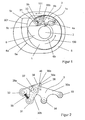
- FIG. 1 and FIG. 2 show a first inventive embodiment of a transport cylinder with a movably mounted in a recess 1 a gripper device 3 or an end view detail of a gripper device 3.
- the rotatable mounted about its axis 2 in a printing press cylinder 1 has for this purpose a recess 1 a, in which the gripper device 3 is movably mounted.
- the gripper device 3 in this case has respective side plates 30a, which e.g. are connected to each other via a gripper shaft 37 and / or the support elements 38.
- On the gripper shaft 37 are a number of gripper elements 36 e.g. fastened by fastening elements 36a such that they are rotatable about the axis of the gripper shaft 37 and can be rotated, for example, via a control arm 30b fastened to the fastening elements 36a so that the front edge 36b of the gripper element 36 rests on a support element 38 in a first position and in a second position is lifted from this.
- the gripper elements or the support elements corresponding stops 40 for the leading edge of the sheet to be held, so that they can be clamped in a defined position of the grippers 36 between the leading edges 36 b and the support pieces 38.
- the control of the gripper elements for opening and closing the gripper can for example take place in that the control arm 30b at its end facing away from the gripper shaft has a roller 31 which rolls, for example, along the control cam 6a of a cam 6, wherein a further attached to the side plate 3 caster 32 acts as an abutment and this rolls along a cam 5a of a cam 5.
- this can be correspondingly shortened or extended, whereby the gripper elements 36 are either closed or opened.
- a mechanical bias for example via a spring 35 prevents an uncontrolled state of the gripper.
- a compression spring 35 the shaft 37 remote from the end of the control arm 30b with the roller 31 resiliently supported on a region of the side plate 3 with the roller 32.
- the side parts 30a each have further rollers 33, 34 which run in corresponding mounted on the transport cylinder 1 KurvenausEnglishept or slide rails 4a, 4b and depending on their design and shape, a rotation and / or tilting of the gripper device 3 about a parallel to the cylinder axis. 2 allow extending axis of rotation.
- the shape of the control cams 5a, 6a of the cams 5, 6 further cause the gripper device 3 is moved out of the recess 1 a either by rotation of the transport cylinder 1 about its axis 2 in the direction 100 depending on the rotational position of the transport cylinder 1 or moved into this is or remains in this for a certain rotation angle range.
- the gripper device 3 is continuously moved out of the recess 1a.
- rollers 33, 34 are moved in the slide rails 4a, 4b, which can be done depending on the shape and design, a continuous rotation and / or tilting of the gripper device, so as for example the leading edge of the bow support 38 and gripper tip 36b clamped sheet in a to move rectilinear movement direction 101.
- the rolling on the cam 5a roller 32 reaches the area 5c of the control cam 5a and on the Control cam 6a rolling roller 31, the area 6c of the control cam 6, whereby the effective distance of the rollers 31, 32 is increased to each other so that the gripper 36 opens and thus releases the sheet while the gripper device 3 from the linear direction of movement 101 substantially in the direction 100 is moved away and thus the sheet can be freely moved in the direction 101 by a subsequent transport means, not shown.
- the hook tip moves on a path which is represented by the dashed line 301.
- FIGS. 3a to 3f To illustrate the movements show the FIGS. 3a to 3f the rotation of a transport cylinder in different positions.
- FIG. 3a in this case shows a transport cylinder 1 with a spanned on its lateral surface sheet 200, the front edge 201 is clamped by the front edge 36b of the gripper 36 of the gripper device 3. At this time, the gripper device 3 is in the recess 1 a of the transport cylinder below the outer surface surface of the cylinder, so that a rollover by a pressure cylinder 10 is easily possible.
- the leading edge 201 of the sheet 200 in the defined by the distance of the transport cylinder 1 and the printing cylinder 10 printing gap 11 so that a printing of the sheet 200 can be done via the printing cylinder 11.
- the roller 32 passes into the region 5b of the control cam 5 whereby the gripper device 3 is continuously moved out of the recess 1a of the transport cylinder 1 in a further rotation of the transport cylinder 1 in the direction 100.
- the gripper device 3 is rotated and / or tilted so that the support surface 38a of the gripper pad 38 is always parallel to the direction of movement 101 and along to this, so that the leading edge of the gripper device 33 along the guide rollers 4a, 4b along the guide rollers 4a, 4b 201 of the sheet 200 performs a rectilinear motion along the direction 101, as in FIGS FIGS. 3b and 3c shown.
- the moving out thus takes place in the tangential direction to the transport cylinder.
- After another rotation angle as in 3d figure finally shows the roller 32 in the region 5c of the control cam 5 and the roller 31 in the region 6c of the control cam 6, whereby the gripper 36 opens and the front edge 210 of the sheet 200 releases.
- the gripper device 3 is pivoted out of the sheet transport direction 101 in the direction 100 by the rotation of the transport cylinder 1, so that the sheet can easily be transported away in the direction 101 by means of a subsequent transport device, as in FIG. 3e shown.
- a subsequent transport device as in FIG. 3e shown.
- FIG. 4 shows a further arrangement of a transport cylinder 1 according to the invention with two gripper devices 3a, 3b in a printing press.
- the sheets 200 to be processed are transferred from an upstream transport cylinder 12 to the transport cylinder 1 according to the invention in its point of contact, wherein the peripheral speeds 100, 112 of both cylinders in the transfer point have the same direction and are adapted to each other that a positionally accurate and easy transfer take place can.
- one or more impression cylinders 10 are arranged on the transport cylinder 1, whereby the sheet located on the transport cylinder can be printed or painted.
- the direction of rotation 110 and the speed of the printing cylinder is the Direction of rotation and speed of the transport cylinder 1 adjusted so that a register-accurate and easy printing or painting of the sheet can be done.
- the transport cylinder acts in this example additionally as impression cylinder.
- a conveyor belt 13 is attached to the transport cylinder 1 according to the invention that a printed or painted sheet by means of the movable gripper device 3a, 3b as far as can be pulled onto the conveyor belt 13 that the sheet at least can be fixed in its front region by, for example, located on the conveyor belt 13 gripper devices or a vacuum suction device and can be transported safely from the conveyor belt 13.
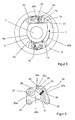
- FIG. 5 and FIG. 6 show a further embodiment of the invention a transport cylinder 1 with two movably mounted in a respective recess gripper devices 3a, 3b and an end view detail of one of the gripper devices 3a, 3b.
- the gripper devices 3a, 3b in each case have side plates 30a, which are connected to one another via a gripper shaft 37.
- a number of gripper elements 36 are fastened via fasteners 36a so that they are rotatable about the axis of the gripper shaft 37 and can be rotated, for example via a attached to the fasteners 36a control arm 30b so that the leading edge 36b of the gripper element 36 in a first position rests on a support piece 38 and is lifted in a second position of this.
- the gripper elements have corresponding stops 40 for the leading edge of the sheet to be held, so that it can be clamped in a defined position by the grippers 36 between the leading edges 36b and the support pieces 38.
- Each gripper device 3a, 3b also has in a similar manner as already described on each rollers 33, 34, which run in corresponding mounted on the transport cylinder 1 KurvenausEnglishept or slide rails 4a, 4b and depending on their design and shape, a rotation and / or tilting of the gripper device 3 allow a parallel to the cylinder axis 2 extending axis of rotation.
- the Kurvenausnaturalened 4a, 4b are further designed so that the gripper device 3a, 3b can be moved out of its respective recess 1 a, 1b that the respective gripper pad 38 within a certain angular range travels a tangential to the outer surface of the transport cylinder travel, the Distance is substantially centered to the cylinder axis.
- the shape and design of the curve recesses 4a, 4b are designed so that a rotation and / or tilting of the gripper device can take place simultaneously, whereby it is possible to guide the support surface 38a of the gripper support 38 within the tangential path parallel to it a sheet leading edge held between gripper pad 38 and gripper leading edge 36b does not undergo buckling.
- rollers 31, 32 are respectively provided on the gripper device 3a, 3b, which, as already described, for example, roll along a respective running surface 5a, 6a of stationary cam disks 5, 6.
- the gripper devices 3a, 3b at certain rotational angular positions of the transport cylinder 1 from their respective recess 1 a, 1 b move out or move into this, so that within a certain Rotation angle range of the transport cylinder 1 and a rectilinear motion at least a rectilinear movement of the support surface 38a of the gripper device 3a, 3b is achieved.
- roller 31 always on the running surface 5a and the roller 32 always roll on the running surface 6a of the respective cam discs 5, 6 results between the rollers 31, 32 a rotation angle dependent effective distance, which by the shape of the cam at certain positions so can be made smaller that the gripper members 36 are opened via the lever 30 b, for example, to grab or release the leading edge of a sheet 200.
- FIGS. 7a to 7c show schematically three different positions of a second embodiment of a transport cylinder according to the invention.
- a first position of the gripper device 3a as in Figure 7a the gripper device 3a is thus moved out of the recess 1a of the transport cylinder 1 over the lateral surface of the transport cylinder and rotated accordingly and / or tilted that the leading edge of a supplied by an unillustrated transport system upstream sheet 200 can be detected by the hook tip 36b.
- the gripping device 3a can again be completely immersed in its associated recess 1a, so that, for example, a printing of the sheet can take place with a pressure roller (not shown).
- a third position like in FIG. 7c shown schematically, the gripper device 3a in turn out of the associated recess 1 a moved out and rotated accordingly and / or tilted that the transported sheet to a not shown downstream transport device can be handed over.
- the sheet is continuously moved further in a rectilinear movement direction 101 by means of the transport cylinder and, in particular, the front edge of the sheet 200 gripped by the gripper elements 36 undergoes no kinking.
Landscapes
- Feeding Of Articles By Means Other Than Belts Or Rollers (AREA)
- Supply, Installation And Extraction Of Printed Sheets Or Plates (AREA)
Applications Claiming Priority (1)
| Application Number | Priority Date | Filing Date | Title |
|---|---|---|---|
| DE102007061556A DE102007061556B4 (de) | 2007-12-18 | 2007-12-18 | Transportzylinder, mit beweglicher Greifervorrichtung und Verfahren zum Transportieren von Bögen |
Publications (2)
| Publication Number | Publication Date |
|---|---|
| EP2072254A2 true EP2072254A2 (fr) | 2009-06-24 |
| EP2072254A3 EP2072254A3 (fr) | 2011-06-22 |
Family
ID=40532603
Family Applications (1)
| Application Number | Title | Priority Date | Filing Date |
|---|---|---|---|
| EP08021511A Withdrawn EP2072254A3 (fr) | 2007-12-18 | 2008-12-11 | Cylindre de transport doté d'un dispositif de préhension mobile |
Country Status (4)
| Country | Link |
|---|---|
| US (1) | US20090152808A1 (fr) |
| EP (1) | EP2072254A3 (fr) |
| CN (1) | CN101481052A (fr) |
| DE (1) | DE102007061556B4 (fr) |
Cited By (1)
| Publication number | Priority date | Publication date | Assignee | Title |
|---|---|---|---|---|
| DE102015017169B4 (de) | 2015-11-23 | 2024-12-12 | Koenig & Bauer Ag | Vorrichtung zur Bearbeitung von Substraten |
Families Citing this family (7)
| Publication number | Priority date | Publication date | Assignee | Title |
|---|---|---|---|---|
| EP2701918B1 (fr) * | 2011-04-28 | 2015-06-03 | Hewlett-Packard Development Company, L.P. | Agencement de préhension de médias imprimés |
| EP3694717B1 (fr) * | 2017-10-13 | 2021-12-01 | Koenig & Bauer AG | Machine de traitement de feuilles dotée d'un dispositif de transport de feuilles et procédé de transport de feuilles d'un cylindre de guidage de feuilles vers un système de transport de feuilles |
| DE102020209465B3 (de) * | 2020-07-28 | 2021-07-15 | Heidelberger Druckmaschinen Aktiengesellschaft | Druckplatten-Greifsystem |
| CN113022099B (zh) * | 2021-02-26 | 2022-08-26 | 重庆市金利药包材料有限公司 | 一种药用包装袋生产装置 |
| CN114474969B (zh) * | 2022-03-11 | 2025-10-24 | 新乡李印机械科技有限公司 | 咬纸牙机构及旋转丝网印刷机 |
| CN114653549B (zh) * | 2022-04-22 | 2025-12-30 | 广州钇鑫包装机械有限公司 | 一种辊印印刷品在线二次涂布机 |
| CN117735304A (zh) * | 2023-12-21 | 2024-03-22 | 杭州爱科自动化技术有限公司 | 一种瓦楞纸送纸设备及送纸方法 |
Citations (1)
| Publication number | Priority date | Publication date | Assignee | Title |
|---|---|---|---|---|
| DE1954559A1 (de) | 1969-10-30 | 1971-05-06 | Karl Raes | Vorrichtung zur Bogenuebergabe an rotierende Druckzylinder |
Family Cites Families (18)
| Publication number | Priority date | Publication date | Assignee | Title |
|---|---|---|---|---|
| DE366370C (de) * | 1921-01-29 | 1923-01-04 | Bautzner Ind Akt Ges | Greifervorrichtung mit veraenderlicher Geschwindigkeit des Greifers in Richtung des Zylinderumfanges fuer Maschinen mit umlaufendem Druckzylinder |
| FR2130961A5 (fr) * | 1971-03-29 | 1972-11-10 | Carnaud & Forges | |
| DE2557866B2 (de) * | 1975-12-22 | 1977-11-03 | Heidelberger Druckmaschinen Ag, 6900 Heidelberg | Rotierende vorgreifertrommel |
| US4132403A (en) * | 1977-07-07 | 1979-01-02 | Veb Polygraph Leipzig Kombinat Fuer Polygraphische Maschinen Und Ausruestungen | Sheet transfer apparatus for printing machine |
| DD142694A1 (de) * | 1979-04-02 | 1980-07-09 | Guenter Weisbach | Bogenrotationsdruckmaschine mit einem von unten arbeitenden vorgreifer |
| DE3311196A1 (de) * | 1983-03-26 | 1984-10-04 | Heidelberger Druckmaschinen Ag, 6900 Heidelberg | Verfahren zur fliessenden anlage von boegen |
| DE3621384A1 (de) * | 1986-06-26 | 1988-01-14 | Roland Man Druckmasch | Vorrichtung zum antrieb eines schwingenden vorgreifers einer druckmaschine |
| US4858910A (en) * | 1987-01-22 | 1989-08-22 | M.A.N. Roland Druckmaschinen | Conveyor for a sheet-fed rotary press |
| DE3836544A1 (de) * | 1988-10-27 | 1990-05-03 | Rotaprint Gmbh | Gegendruckzylinder mit greifersystem |
| DE4139667C2 (de) * | 1991-12-02 | 1997-02-06 | Kba Planeta Ag | Antrieb für ein Schwingsystem in einem Bogenführungszylinder einer Bogenrotationsdruckmaschine |
| DE4210327A1 (de) * | 1992-03-30 | 1993-10-07 | Koenig & Bauer Ag | Bogenwendeeinrichtung in einer Rotationsdruckmaschine |
| DE4230218C2 (de) * | 1992-09-10 | 1999-06-10 | Heidelberger Druckmasch Ag | Vorgreifer einer Bogendruckmaschine |
| US5762333A (en) * | 1994-08-31 | 1998-06-09 | Komori Corporation | Sheet reversing apparatus for sheet-fed rotary press with reversing mechanism |
| DE19617492C2 (de) * | 1996-05-02 | 2001-02-01 | Koenig & Bauer Ag | Antrieb für Greifer in Wendetrommeln |
| DE19833903A1 (de) * | 1998-07-28 | 2000-02-03 | Heidelberger Druckmasch Ag | Verfahren zur Übernahme einer Bogenhinterkante von einem vorgeordneten Zylinder einer Bogenrotationsdruckmaschine |
| DE10156800B4 (de) * | 2000-12-19 | 2014-12-24 | Heidelberger Druckmaschinen Ag | Druckwerk |
| DE10122227B4 (de) * | 2001-05-08 | 2012-03-01 | Koenig & Bauer Aktiengesellschaft | Speichertrommel in Wendeeinrichtungen von Bogendruckmaschinen |
| DE10310375B4 (de) * | 2002-03-09 | 2012-04-05 | Kba-Meprint Ag | Bogenzuführtrommel |
-
2007
- 2007-12-18 DE DE102007061556A patent/DE102007061556B4/de not_active Expired - Fee Related
-
2008
- 2008-12-10 US US12/331,714 patent/US20090152808A1/en not_active Abandoned
- 2008-12-11 EP EP08021511A patent/EP2072254A3/fr not_active Withdrawn
- 2008-12-18 CN CNA2008101909694A patent/CN101481052A/zh active Pending
Patent Citations (1)
| Publication number | Priority date | Publication date | Assignee | Title |
|---|---|---|---|---|
| DE1954559A1 (de) | 1969-10-30 | 1971-05-06 | Karl Raes | Vorrichtung zur Bogenuebergabe an rotierende Druckzylinder |
Cited By (1)
| Publication number | Priority date | Publication date | Assignee | Title |
|---|---|---|---|---|
| DE102015017169B4 (de) | 2015-11-23 | 2024-12-12 | Koenig & Bauer Ag | Vorrichtung zur Bearbeitung von Substraten |
Also Published As
| Publication number | Publication date |
|---|---|
| DE102007061556B4 (de) | 2011-06-09 |
| DE102007061556A1 (de) | 2009-07-02 |
| US20090152808A1 (en) | 2009-06-18 |
| EP2072254A3 (fr) | 2011-06-22 |
| CN101481052A (zh) | 2009-07-15 |
Similar Documents
| Publication | Publication Date | Title |
|---|---|---|
| DE102007061556B4 (de) | Transportzylinder, mit beweglicher Greifervorrichtung und Verfahren zum Transportieren von Bögen | |
| EP2869991B1 (fr) | Dispositif de transport et procédé de transport de feuilles imprimées, notamment de feuilles rigides | |
| EP1136263A2 (fr) | Dispositif pour transporter une feuille pour une machine d'impression rotative | |
| DE102017111309A1 (de) | Bogenübernahme in Anlegeeinheit | |
| DE102015208915B4 (de) | Maschine zur mehrstufigen Be- und/oder Verarbeitung von bogenförmigen Bedruckstoffen sowie Anlage und Verfahren zur Herstellung von Druckprodukten | |
| EP2869993A1 (fr) | Dispositif de transport et procédé destinés à transporter des feuilles en matière imprimée en assurant un mouvement d'avance souple | |
| DE941484C (de) | Greifvorrichtung fuer Druckmaschinen | |
| DE102008031500A1 (de) | Einzelblatt-Druckmaschine | |
| DE102013226315B4 (de) | Bogenverarbeitende Maschine mit einem Bearbeitungswerk und einer Auslage | |
| EP0968821A2 (fr) | Cylindre à transport des feuilles dans une presse à feuilles rotative | |
| EP3694719B1 (fr) | Machine de traitement de feuilles dotée d'un dispositif de transport de feuilles, et procédé pour transporter des feuilles, d'un cylindre de guidage de feuilles à un système convoyeur de feuilles | |
| DE102017218407B4 (de) | Bogentransportvorrichtung und Verfahren zum Transportieren von Bogen von einem Bogenführungszylinder an ein Bogenfördersystem | |
| DE102008014811B4 (de) | Vorrichtung zum Fördern eines Bogens durch eine bogenverarbeitende Maschine | |
| EP3694717B1 (fr) | Machine de traitement de feuilles dotée d'un dispositif de transport de feuilles et procédé de transport de feuilles d'un cylindre de guidage de feuilles vers un système de transport de feuilles | |
| EP3694718B1 (fr) | Machine de traitement de feuilles dotée d'un dispositif de transport de feuilles et procédé de transport de feuilles d'un cylindre de guidage de feuilles vers un système de transport de feuilles | |
| DE102013217097B4 (de) | Auslagevorrichtung für eine bogenverarbeitende Maschine mit einem ersten Fördersystem für Bogenvorderkanten und einem zweiten Fördersystem für Bogenhinterkanten, Verfahren zum Transportieren von Bogen und Verwendung einer Aufpressbewegung zur Saugluftsteuerung | |
| DE102017218410A1 (de) | Bogentransportvorrichtung und Verfahren zum Transportieren von Bogen von einem Bogenführungszylinder an ein Bogenfördersystem | |
| DE102013220052B4 (de) | Auslagevorrichtung einer bogenverarbeitenden Maschine mit einem Bogenfördersystem zum Transport von Bogen zu einem Bogenstapel und Verfahren zum Transport von Bogen | |
| DE102017204913A1 (de) | Verfahren zum Aufziehen einer Platte sowie eine Druckmaschine zur Durchführung des Verfahrens | |
| DE102024119614A1 (de) | Auslage und Verfahren zum Betreiben einer Auslage | |
| DE102013223755B4 (de) | Falzapparat für eine in unterschiedlichen Produktionen unterschiedliche Druckerzeugnisse produzierende Rollendruckmaschine | |
| DE102017012198B4 (de) | Bogentransportvorrichtung und Verfahren zum Transportieren von Bogen von einem Bogenführungszylinder an ein Bogenfördersystem | |
| DE102017218411B4 (de) | Bogentransportvorrichtung und Verfahren zum Transportieren von Bogen von einem Bogenführungszylinder an ein Bogenfördersystem | |
| WO2025163052A1 (fr) | Dispositif dans une presse d'impression offset de feuilles pour une impression sur des feuilles imprimées | |
| DE102024102839A1 (de) | Vorrichtung in einer Bogenoffsetdruckmaschine zum Eindrucken in unbedruckte oder bedruckte Druckbogen |
Legal Events
| Date | Code | Title | Description |
|---|---|---|---|
| PUAI | Public reference made under article 153(3) epc to a published international application that has entered the european phase |
Free format text: ORIGINAL CODE: 0009012 |
|
| AK | Designated contracting states |
Kind code of ref document: A2 Designated state(s): AT BE BG CH CY CZ DE DK EE ES FI FR GB GR HR HU IE IS IT LI LT LU LV MC MT NL NO PL PT RO SE SI SK TR |
|
| AX | Request for extension of the european patent |
Extension state: AL BA MK RS |
|
| RAP1 | Party data changed (applicant data changed or rights of an application transferred) |
Owner name: KBA-METROPRINT AG |
|
| PUAL | Search report despatched |
Free format text: ORIGINAL CODE: 0009013 |
|
| AK | Designated contracting states |
Kind code of ref document: A3 Designated state(s): AT BE BG CH CY CZ DE DK EE ES FI FR GB GR HR HU IE IS IT LI LT LU LV MC MT NL NO PL PT RO SE SI SK TR |
|
| AX | Request for extension of the european patent |
Extension state: AL BA MK RS |
|
| 17P | Request for examination filed |
Effective date: 20110701 |
|
| GRAP | Despatch of communication of intention to grant a patent |
Free format text: ORIGINAL CODE: EPIDOSNIGR1 |
|
| AKX | Designation fees paid |
Designated state(s): AT BE BG CH CY CZ DE DK EE ES FI FR GB GR HR HU IE IS IT LI LT LU LV MC MT NL NO PL PT RO SE SI SK TR |
|
| STAA | Information on the status of an ep patent application or granted ep patent |
Free format text: STATUS: THE APPLICATION IS DEEMED TO BE WITHDRAWN |
|
| 18D | Application deemed to be withdrawn |
Effective date: 20120306 |