EP2072316A2 - System und Verfahren zur Unterstützung beim Einhalten eines Abstands zwischen Fahrzeugen - Google Patents
System und Verfahren zur Unterstützung beim Einhalten eines Abstands zwischen Fahrzeugen Download PDFInfo
- Publication number
- EP2072316A2 EP2072316A2 EP08172058A EP08172058A EP2072316A2 EP 2072316 A2 EP2072316 A2 EP 2072316A2 EP 08172058 A EP08172058 A EP 08172058A EP 08172058 A EP08172058 A EP 08172058A EP 2072316 A2 EP2072316 A2 EP 2072316A2
- Authority
- EP
- European Patent Office
- Prior art keywords
- confidence factor
- inter
- obstacle
- host vehicle
- vehicle
- Prior art date
- Legal status (The legal status is an assumption and is not a legal conclusion. Google has not performed a legal analysis and makes no representation as to the accuracy of the status listed.)
- Granted
Links
Images


Classifications
-
- B—PERFORMING OPERATIONS; TRANSPORTING
- B60—VEHICLES IN GENERAL
- B60K—ARRANGEMENT OR MOUNTING OF PROPULSION UNITS OR OF TRANSMISSIONS IN VEHICLES; ARRANGEMENT OR MOUNTING OF PLURAL DIVERSE PRIME-MOVERS IN VEHICLES; AUXILIARY DRIVES FOR VEHICLES; INSTRUMENTATION OR DASHBOARDS FOR VEHICLES; ARRANGEMENTS IN CONNECTION WITH COOLING, AIR INTAKE, GAS EXHAUST OR FUEL SUPPLY OF PROPULSION UNITS IN VEHICLES
- B60K31/00—Vehicle fittings, acting on a single sub-unit only, for automatically controlling vehicle speed, i.e. preventing speed from exceeding an arbitrarily established velocity or maintaining speed at a particular velocity, as selected by the vehicle operator
- B60K31/0008—Vehicle fittings, acting on a single sub-unit only, for automatically controlling vehicle speed, i.e. preventing speed from exceeding an arbitrarily established velocity or maintaining speed at a particular velocity, as selected by the vehicle operator including means for detecting potential obstacles in vehicle path
-
- B—PERFORMING OPERATIONS; TRANSPORTING
- B60—VEHICLES IN GENERAL
- B60W—CONJOINT CONTROL OF VEHICLE SUB-UNITS OF DIFFERENT TYPE OR DIFFERENT FUNCTION; CONTROL SYSTEMS SPECIALLY ADAPTED FOR HYBRID VEHICLES; ROAD VEHICLE DRIVE CONTROL SYSTEMS FOR PURPOSES NOT RELATED TO THE CONTROL OF A PARTICULAR SUB-UNIT
- B60W30/00—Purposes of road vehicle drive control systems not related to the control of a particular sub-unit, e.g. of systems using conjoint control of vehicle sub-units
- B60W30/08—Active safety systems predicting or avoiding probable or impending collision or attempting to minimise its consequences
- B60W30/095—Predicting travel path or likelihood of collision
-
- B—PERFORMING OPERATIONS; TRANSPORTING
- B60—VEHICLES IN GENERAL
- B60W—CONJOINT CONTROL OF VEHICLE SUB-UNITS OF DIFFERENT TYPE OR DIFFERENT FUNCTION; CONTROL SYSTEMS SPECIALLY ADAPTED FOR HYBRID VEHICLES; ROAD VEHICLE DRIVE CONTROL SYSTEMS FOR PURPOSES NOT RELATED TO THE CONTROL OF A PARTICULAR SUB-UNIT
- B60W30/00—Purposes of road vehicle drive control systems not related to the control of a particular sub-unit, e.g. of systems using conjoint control of vehicle sub-units
- B60W30/14—Adaptive cruise control
- B60W30/16—Control of distance between vehicles, e.g. keeping a distance to preceding vehicle
-
- B—PERFORMING OPERATIONS; TRANSPORTING
- B60—VEHICLES IN GENERAL
- B60W—CONJOINT CONTROL OF VEHICLE SUB-UNITS OF DIFFERENT TYPE OR DIFFERENT FUNCTION; CONTROL SYSTEMS SPECIALLY ADAPTED FOR HYBRID VEHICLES; ROAD VEHICLE DRIVE CONTROL SYSTEMS FOR PURPOSES NOT RELATED TO THE CONTROL OF A PARTICULAR SUB-UNIT
- B60W50/00—Details of control systems for road vehicle drive control not related to the control of a particular sub-unit, e.g. process diagnostic or vehicle driver interfaces
- B60W50/0097—Predicting future conditions
-
- B—PERFORMING OPERATIONS; TRANSPORTING
- B60—VEHICLES IN GENERAL
- B60W—CONJOINT CONTROL OF VEHICLE SUB-UNITS OF DIFFERENT TYPE OR DIFFERENT FUNCTION; CONTROL SYSTEMS SPECIALLY ADAPTED FOR HYBRID VEHICLES; ROAD VEHICLE DRIVE CONTROL SYSTEMS FOR PURPOSES NOT RELATED TO THE CONTROL OF A PARTICULAR SUB-UNIT
- B60W50/00—Details of control systems for road vehicle drive control not related to the control of a particular sub-unit, e.g. process diagnostic or vehicle driver interfaces
- B60W50/08—Interaction between the driver and the control system
- B60W50/14—Means for informing the driver, warning the driver or prompting a driver intervention
- B60W50/16—Tactile feedback to the driver, e.g. vibration or force feedback to the driver on the steering wheel or the accelerator pedal
-
- B—PERFORMING OPERATIONS; TRANSPORTING
- B60—VEHICLES IN GENERAL
- B60W—CONJOINT CONTROL OF VEHICLE SUB-UNITS OF DIFFERENT TYPE OR DIFFERENT FUNCTION; CONTROL SYSTEMS SPECIALLY ADAPTED FOR HYBRID VEHICLES; ROAD VEHICLE DRIVE CONTROL SYSTEMS FOR PURPOSES NOT RELATED TO THE CONTROL OF A PARTICULAR SUB-UNIT
- B60W2520/00—Input parameters relating to overall vehicle dynamics
- B60W2520/10—Longitudinal speed
-
- B—PERFORMING OPERATIONS; TRANSPORTING
- B60—VEHICLES IN GENERAL
- B60W—CONJOINT CONTROL OF VEHICLE SUB-UNITS OF DIFFERENT TYPE OR DIFFERENT FUNCTION; CONTROL SYSTEMS SPECIALLY ADAPTED FOR HYBRID VEHICLES; ROAD VEHICLE DRIVE CONTROL SYSTEMS FOR PURPOSES NOT RELATED TO THE CONTROL OF A PARTICULAR SUB-UNIT
- B60W2520/00—Input parameters relating to overall vehicle dynamics
- B60W2520/14—Yaw
-
- B—PERFORMING OPERATIONS; TRANSPORTING
- B60—VEHICLES IN GENERAL
- B60W—CONJOINT CONTROL OF VEHICLE SUB-UNITS OF DIFFERENT TYPE OR DIFFERENT FUNCTION; CONTROL SYSTEMS SPECIALLY ADAPTED FOR HYBRID VEHICLES; ROAD VEHICLE DRIVE CONTROL SYSTEMS FOR PURPOSES NOT RELATED TO THE CONTROL OF A PARTICULAR SUB-UNIT
- B60W2540/00—Input parameters relating to occupants
- B60W2540/10—Accelerator pedal position
- B60W2540/103—Accelerator thresholds, e.g. kickdown
-
- B—PERFORMING OPERATIONS; TRANSPORTING
- B60—VEHICLES IN GENERAL
- B60W—CONJOINT CONTROL OF VEHICLE SUB-UNITS OF DIFFERENT TYPE OR DIFFERENT FUNCTION; CONTROL SYSTEMS SPECIALLY ADAPTED FOR HYBRID VEHICLES; ROAD VEHICLE DRIVE CONTROL SYSTEMS FOR PURPOSES NOT RELATED TO THE CONTROL OF A PARTICULAR SUB-UNIT
- B60W2552/00—Input parameters relating to infrastructure
- B60W2552/15—Road slope, i.e. the inclination of a road segment in the longitudinal direction
-
- B—PERFORMING OPERATIONS; TRANSPORTING
- B60—VEHICLES IN GENERAL
- B60W—CONJOINT CONTROL OF VEHICLE SUB-UNITS OF DIFFERENT TYPE OR DIFFERENT FUNCTION; CONTROL SYSTEMS SPECIALLY ADAPTED FOR HYBRID VEHICLES; ROAD VEHICLE DRIVE CONTROL SYSTEMS FOR PURPOSES NOT RELATED TO THE CONTROL OF A PARTICULAR SUB-UNIT
- B60W2554/00—Input parameters relating to objects
- B60W2554/40—Dynamic objects, e.g. animals, windblown objects
- B60W2554/404—Characteristics
- B60W2554/4041—Position
-
- B—PERFORMING OPERATIONS; TRANSPORTING
- B60—VEHICLES IN GENERAL
- B60W—CONJOINT CONTROL OF VEHICLE SUB-UNITS OF DIFFERENT TYPE OR DIFFERENT FUNCTION; CONTROL SYSTEMS SPECIALLY ADAPTED FOR HYBRID VEHICLES; ROAD VEHICLE DRIVE CONTROL SYSTEMS FOR PURPOSES NOT RELATED TO THE CONTROL OF A PARTICULAR SUB-UNIT
- B60W2554/00—Input parameters relating to objects
- B60W2554/80—Spatial relation or speed relative to objects
- B60W2554/801—Lateral distance
-
- B—PERFORMING OPERATIONS; TRANSPORTING
- B60—VEHICLES IN GENERAL
- B60W—CONJOINT CONTROL OF VEHICLE SUB-UNITS OF DIFFERENT TYPE OR DIFFERENT FUNCTION; CONTROL SYSTEMS SPECIALLY ADAPTED FOR HYBRID VEHICLES; ROAD VEHICLE DRIVE CONTROL SYSTEMS FOR PURPOSES NOT RELATED TO THE CONTROL OF A PARTICULAR SUB-UNIT
- B60W2710/00—Output or target parameters relating to a particular sub-units
- B60W2710/06—Combustion engines, Gas turbines
- B60W2710/0666—Engine torque
Definitions
- the present invention relates to an inter-vehicle distance maintenance supporting system and an inter-vehicle distance maintenance supporting method. Aspects of the invention relate to an apparatus, to a system, to a method and to a vehicle.
- Japanese Kokai Patent Application No. 2004-249891 describes an auxiliary device for driving vehicles. With this device, based on a confidence factor of false recognition and a confidence factor that an object is not present, a risk potential is computed and, corresponding to the risk potential, a pattern of change in the reaction force generated in the vehicle equipment is corrected, so that the reaction force characteristics are taken to be good characteristics when the obstacle is not an object for reaction force control.
- Embodiments of the invention may provide an apparatus, a system or a method which can prevent such a feeling of discomfort.
- Other aims and advantages of the invention will become apparent from the following description, claims and drawings.
- an inter-vehicle distance maintenance supporting system for a host vehicle comprising an obstacle detector configured to detect an obstacle ahead of the host vehicle, an inter-vehicle distance detector configured to detect an inter-vehicle distance between the host vehicle and the obstacle, a confidence factor computing device configured to compute a confidence factor for treating the obstacle as a preceding vehicle ahead of the host vehicle based on a state of the obstacle detected by the obstacle detector, a confidence factor correcting part configured to correct the confidence factor based on a relative-position relationship between the host vehicle and the obstacle, and a reaction force controller configured to apply a reaction force on an accelerator pedal of the host vehicle based on the inter-vehicle distance detected by the inter-vehicle distance detector and the confidence factor corrected by the confidence factor correcting part.
- the system may comprise an accelerator pedal depression detector configured to detect depression of the accelerator pedal.
- the confidence factor correcting part is configured to reduce the confidence factor when the accelerator pedal depression detector detects the depression of the accelerator pedal.
- the confidence factor correcting part is configured to reduce the confidence factor as the inter-vehicle distance becomes smaller.
- the system may comprise a yaw rate detector configured to detect a yaw rate of the host vehicle.
- the confidence factor computing device is configured to use the yaw rate detected by the yaw rate detector to compute a predicted path of the host vehicle, and compute the confidence factor from a relative position of the obstacle with respect to the predicted path.
- the confidence factor correcting part is configured to correct the confidence factor by filtering of the yaw rate.
- the confidence factor correcting part is configured to increase a cutoff frequency used in the filtering as the inter-vehicle distance becomes smaller.
- the confidence factor correcting part is configured to compute the relative position of the obstacle after a prescribed time with respect to the predicted path, and to use the relative position of the obstacle after the prescribed time to compute the confidence factor.
- the confidence factor correcting part is configured to increase the prescribed time as the inter-vehicle distance becomes smaller.
- the confidence factor correcting part is configured to change a coefficient used in computing the confidence factor based on the inter-vehicle distance.
- the confidence factor correcting part is configured to increase an absolute value of the coefficient as inter-vehicle distances becomes shorter.
- the confidence factor correcting part is configured to reduce the confidence factor when the accelerator pedal depression detector detects depression of the accelerator pedal, and to continue to reduce the confidence factor for a prescribed time after depression of the accelerator pedal is ended.
- the reaction force controller is configured to increase the reaction force as the confidence factor corrected by the confidence factor correcting part becomes larger.
- an inter-vehicle distance maintenance supporting system for a host vehicle comprising an obstacle detector configured to detect an obstacle ahead of the host vehicle, an inter-vehicle distance detector configured to detect an inter-vehicle distance between the host vehicle and the obstacle, a confidence factor computing device configured to compute a confidence factor for treating the obstacle as a preceding vehicle ahead of the host vehicle based on a state of the obstacle detected by the obstacle detector, an accelerator pedal depression detector configured to detect depression of an accelerator pedal, a confidence factor correcting part configured to correct the confidence factor based on the depression of the accelerator pedal and a reaction force controller configured to apply a reaction force on the accelerator pedal based on the inter-vehicle distance detected by the inter-vehicle distance detector and the confidence factor corrected by the confidence factor correcting part.
- an inter-vehicle distance maintenance supporting method for a host vehicle comprising detecting an obstacle ahead of the host vehicle, detecting an inter-vehicle distance between the host vehicle and the obstacle, computing a confidence factor for treating the obstacle as a preceding vehicle of the host vehicle based on a detected obstacle state, correcting the confidence factor based on a relative-position relationship between the host vehicle and the obstacle and applying a reaction force based on the inter-vehicle distance and the corrected confidence factor.
- an inter-vehicle distance maintenance supporting method for a host vehicle comprising detecting an obstacle ahead of the host vehicle, detecting an inter-vehicle distance between the host vehicle and the obstacle, computing a confidence factor for treating the obstacle as a preceding vehicle of the host vehicle based on a detected obstacle state, detecting a depression of an accelerator pedal, correcting the confidence factor based on the depression of the accelerator pedal, and applying a reaction force based on the inter-vehicle distance and the corrected confidence factor.
- an inter-vehicle distance maintenance supporting system for a host vehicle comprising an obstacle detecting means for detecting an obstacle ahead of the host vehicle, an inter-vehicle distance detecting means for detecting an inter-vehicle distance between the host vehicle and the obstacle, a confidence factor computing means for computing a confidence factor for treating the obstacle as a preceding vehicle ahead of the host vehicle based on a state of the obstacle detected by the obstacle detecting means, a confidence factor correcting means for correcting the confidence factor based on a relative-position relationship between the host vehicle and the obstacle and a reaction force controlling means for applying a reaction force on an accelerator pedal based on the inter-vehicle distance detected by the inter-vehicle distance detecting means and the confidence factor corrected by the confidence factor correcting means.
- an inter-vehicle distance maintenance supporting system for a host vehicle comprising an obstacle detecting means for detecting an obstacle ahead of the host vehicle, an inter-vehicle distance detecting means for detecting an inter-vehicle distance between the host vehicle and the obstacle, a confidence factor computing means for computing a confidence factor for treating the obstacle as a preceding vehicle ahead of the host vehicle based on a state of the obstacle detected by the obstacle detecting means, an accelerator pedal depression detecting means for detecting depression of an accelerator pedal, a confidence factor correcting means for correcting the confidence factor based on the depression of the accelerator pedal, and a reaction force controlling means for applying a reaction force on the accelerator pedal based on the inter-vehicle distance detected by the inter-vehicle distance detecting means and the confidence factor corrected by the confidence factor correcting means.
- an inter-vehicle distance maintenance supporting system for a host vehicle may include an obstacle detector configured to detect an obstacle ahead of the host vehicle, an inter-vehicle distance detector configured to detect an inter-vehicle distance between the host vehicle and the obstacle, a confidence factor computing device configured to compute a confidence factor for treating the obstacle as a preceding vehicle ahead of the host vehicle based on a state of the obstacle detected by the obstacle detector, a confidence factor correcting part configured to correct the confidence factor based on a relative-position relationship between the host vehicle and the obstacle, and a reaction force controller configured to apply a reaction force on an accelerator pedal based on the inter-vehicle distance detected by the inter-vehicle distance detector and the confidence factor corrected by the confidence factor correcting part.
- An inter-vehicle distance maintenance supporting system for a host vehicle may include an obstacle detector configured to detect an obstacle ahead of the host vehicle, an inter-vehicle distance detector configured to detect an inter-vehicle distance between the host vehicle and the obstacle, a confidence factor computing device configured to compute a confidence factor for treating the obstacle as a preceding vehicle ahead of the host vehicle based on a state of the obstacle detected by the obstacle detector, an accelerator pedal depression detector configured to detect depression of an accelerator pedal, a confidence factor correcting part configured to correct the confidence factor based on the depression of the accelerator pedal, and a reaction force controller configured to apply a reaction force on the accelerator pedal based on the inter-vehicle distance detected by the inter-vehicle distance detector and the confidence factor corrected by the confidence factor correcting part.
- an inter-vehicle distance maintenance supporting method for a host vehicle may include detecting an obstacle ahead of the host vehicle, detecting an inter-vehicle distance between the host vehicle and the obstacle, computing a confidence factor for treating the obstacle as a preceding vehicle of the host vehicle based on a detected obstacle state, correcting the confidence factor based on a relative-position relationship between the host vehicle and the obstacle, and applying a reaction force based on the inter-vehicle distance and the corrected confidence factor.
- An inter-vehicle distance maintenance supporting method for a host vehicle may include detecting an obstacle ahead of the host vehicle, detecting an inter-vehicle distance between the host vehicle and the obstacle, computing a confidence factor for treating the obstacle as a preceding vehicle of the host vehicle based on a detected obstacle state, detecting a depression of an accelerator pedal, correcting the confidence factor based on the depression of the accelerator pedal, and applying a reaction force based on the inter-vehicle distance and the corrected confidence factor.
- an inter-vehicle distance maintenance supporting system for a host vehicle may include an obstacle detecting means for detecting an obstacle ahead of the host vehicle, an inter-vehicle distance detecting means for detecting an inter-vehicle distance between the host vehicle and the obstacle, a confidence factor computing means for computing a confidence factor for treating the obstacle as a preceding vehicle ahead of the host vehicle based on a state of the obstacle detected by the obstacle detecting means, a confidence factor correcting means for correcting the confidence factor based on a relative-position relationship between the host vehicle and the obstacle, and a reaction force controlling means for applying a reaction force on an accelerator pedal based on the inter-vehicle distance detected by the inter-vehicle distance detecting means and the confidence factor corrected by the confidence factor correcting means.
- An inter-vehicle distance maintenance supporting system for a host vehicle may include an obstacle detecting means for detecting an obstacle ahead of the host vehicle, an inter-vehicle distance detecting means for detecting an inter-vehicle distance between the host vehicle and the obstacle, a confidence factor computing means for computing a confidence factor for treating the obstacle as a preceding vehicle ahead of the host vehicle based on a state of the obstacle detected by the obstacle detecting means, an accelerator pedal depression detecting means for detecting depression of an accelerator pedal, a confidence factor correcting means for correcting the confidence factor based on the depression of the accelerator pedal, and a reaction force controlling means for applying a reaction force on the accelerator pedal based on the inter-vehicle distance detected by the inter-vehicle distance detecting means and the confidence factor corrected by the confidence factor correcting means.
- Figure 1 is a system diagram illustrating the inter-vehicle distance maintenance supporting system 1 of Embodiment 1 of the present invention.
- Figure 2 is a diagram illustrating the vehicle using inter-vehicle distance maintenance supporting system 1.
- laser radar 10 is installed on the front grill or bumper of the vehicle. It emits IR light pulses in the horizontal direction to scan the region ahead of the vehicle. Laser radar 10 measures the reflected waves of IR light pulses reflected from plural reflective objects (usually the rear end of the preceding vehicle) ahead of the host vehicle, and, from the arrival time of the reflected waves, it detects the individual inter-vehicle distances of plural preceding vehicles and their direction. The detected inter-vehicle distance and the direction are output to controller 50.
- the direction of the object ahead of the vehicle can be represented by the relative angle with respect to the host vehicle.
- the laser radar 10 scans about ⁇ 60° of the front region with respect to the normal direction of the front of the host vehicle, and objects ahead of the host vehicle present in the range can be detected.
- vehicle speed sensor 20 detects the speed of the host vehicle by measuring the rotational velocity of the wheels and the rotational velocity from the transmission, and it outputs the detected host vehicle speed to controller 50.
- yaw rate sensor 30 detects the yaw rate of the vehicle, that is, the vehicle turning speed, and it outputs the detected yaw rate to controller 50.
- Controller 50 comprises a CPU as well as ROM, RAM and other CPU peripheral devices. It performs overall control of inter-vehicle distance maintenance supporting system 1. Controller 50 uses the distance information input from laser radar 10 and the host vehicle speed input from vehicle speed sensor 20 to recognize the state of obstacles around the host vehicle, such as the relative distance and the relative speed between the host vehicle and each obstacle as the running state with respect to the obstacle. Based on the obstacle state, controller 50 computes the confidence factor for the obstacle ahead of the host vehicle, the first inter-vehicle distance threshold and the second inter-vehicle distance threshold. Then, it performs the following control based on the computed confidence factor, the first inter-vehicle distance threshold and the second inter-vehicle distance threshold.
- Inter-vehicle distance maintenance supporting system 1 controls the reaction force generated when accelerator pedal 72 is depressed, so that the driver is notified of the surrounding environment, and the inter-vehicle distance maintenance supporting system can thus appropriately assist the driver, especially in maintaining an appropriate inter-vehicle distance with an obstacle ahead of the host vehicle. Also, by controlling the output amount of the engine torque with respect to the depression amount of accelerator pedal 72, in the case of tracking mode, where the obstacle ahead of the host vehicle is tracked, it is possible to reduce operations performed by the driver in correcting accelerator pedal 72 and thus to reduce the physical load on the driver. At the same time, as the depression amount of accelerator pedal 72 is usually larger than that in the related art, by controlling the operation reaction force, it is easier to inform the driver of the operation reaction force generated at accelerator pedal 72.
- Inter-vehicle distance maintenance supporting system 1 also corrects the accelerator pedal operation reaction force and the engine torque output amount corresponding to the confidence factor that there is an obstacle ahead of the host vehicle.
- the confidence factor of the obstacle ahead of the host vehicle is defined as the value indicating the confidence of the presence of an obstacle ahead of the host vehicle, that is, the confidence of the presence of an obstacle ahead of the host vehicle that becomes the object related to control of the operation reaction force and the engine torque. That is, it is defined as the value that represents the confidence of the ability to judge that an obstacle ahead of the host vehicle is indeed a preceding vehicle ahead of the host vehicle.
- control can be released at an earlier time, so that the feeling of discomfort of the driver can be reduced.
- controller 50 computes the confidence factor for the obstacle ahead of the host vehicle from the relationship in lateral position (left/right direction) between the host vehicle and the obstacle ahead of the host vehicle. Then, based on the first inter-vehicle distance threshold for the obstacle ahead of the host vehicle, the target accelerator pedal reaction force is computed, and the computed target accelerator pedal reaction force is corrected corresponding to the confidence factor. The computed target correction value of the accelerator pedal reaction force is output to accelerator pedal reaction force controller 70.
- controller 50 computes the target accelerator opening based on the second inter-vehicle distance threshold with respect to the obstacle ahead of the host vehicle and the accelerator pedal depression amount by the driver. Then, the computed target accelerator opening is corrected corresponding to the confidence factor, and the corrected target accelerator opening is output to engine controller 74. Also, based on the accelerator pedal depression amount by the driver detected by accelerator pedal depression amount detecting part 73, controller 50 judges whether the depression accelerator pedal 72 is depressed. When the target accelerator opening is reset to the accelerator pedal depression amount by the driver, controller 50 outputs the result of the target accelerator opening resetting treatment based on the determined accelerator pedal depression to engine controller 74.
- accelerator pedal reaction force controller 70 controls the torque generated by servo motor 71 assembled in the link mechanism of accelerator pedal 72.
- Servo motor 71 controls the reaction force generated corresponding to the instruction value from accelerator pedal reaction force controller 70, and it can control the depression force generated when the driver depresses accelerator pedal 72 at will.
- accelerator pedal depression amount detecting part 73 is connected via a link mechanism to accelerator pedal 72. Accelerator pedal depression amount detecting part 73 detects the depression amount (operation amount) of accelerator pedal 72 converted to the rotating angle of servo motor 71 via a link mechanism, and outputs it to controller 50.
- the accelerator pedal reaction force when the accelerator pedal reaction force is not controlled, for example, the accelerator pedal reaction force is set to be greater when the operation amount of accelerator pedal 72 is greater.
- the conventional accelerator pedal reaction force characteristics can be realized by means of, for example, the elastic force of a torsion spring (not shown in the figure) set to the rotating center of accelerator pedal 72.
- Engine controller 74 controls the generated engine torque to correspond to the target accelerator opening output from controller 50.
- Engine controller 74 presets a relationship of the engine torque generation amount corresponding to the accelerator pedal depression amount.
- engine controller 74 controls the engine torque by determining the engine torque generation amount based on the target accelerator opening output from controller 50 instead of the actual accelerator pedal depression amount due to depression by the driver, and adjusting the degree of opening of, for example, a throttle valve. That is, the target accelerator opening is the control instruction value of the engine torque.
- FIG. 3 is a block diagram illustrating an arrangement of controller 50.
- controller 50 may comprise the following parts depending on the CPU software: obstacle recognition part 51, confidence factor computing part 52, first inter-vehicle distance threshold computing part 53, accelerator pedal reaction force determining part 54, driver operation judgment part 55, accelerator pedal reaction force correcting part 56, predicted slope value computing part 57, second inter-vehicle distance threshold computing part 58, target accelerator opening computing part 59, accelerator pedal depression operation detecting part 60, and target accelerator opening resetting part 61.
- Obstacle recognition part 51 computes the inter-vehicle distance and relative speed to an obstacle, such as the preceding vehicle, ahead of the host vehicle based on the signal input from laser radar 10. In addition, it detects the state of the obstacle ahead of the host vehicle from the inter-vehicle distance, the relative speed, and the host vehicle speed input from vehicle speed sensor 20. Confidence factor computing part 52 computes the confidence factor of the obstacle preset ahead of the host vehicle based on the yaw rate of the host vehicle input from yaw rate sensor 30.
- First inter-vehicle distance threshold computing part 53 computes the first inter-vehicle distance threshold with respect to the obstacle ahead of the host vehicle based on the obstacle state input from obstacle recognition part 51.
- Accelerator pedal reaction force determining part 54 determines the accelerator pedal reaction force applied on accelerator pedal 72 based on the first inter-vehicle distance threshold computed by first inter-vehicle distance threshold computing part 53 and the inter-vehicle distance input from obstacle recognition part 51.
- Driver operation judgment part 55 judges whether the driver is depressing accelerator pedal 72 based on the accelerator pedal depression amount input from accelerator pedal depression amount detecting part 73 and the confidence factor computed by confidence factor computing part 52.
- Accelerator pedal reaction force correcting part 56 uses the judgment result of driver operation judgment part 55 and the confidence factor computed by confidence factor computing part 52 to correct the accelerator pedal reaction force computed by accelerator pedal reaction force determining part 54, and outputs the corrected accelerator pedal reaction force to accelerator pedal reaction force controller 70.
- Second inter-vehicle distance threshold computing part 58 computes the second inter-vehicle distance threshold with respect to the obstacle ahead of the host vehicle based on the state of the obstacle input from obstacle recognition part 51.
- target accelerator opening computing part 59 computes the target accelerator opening (final value of the target accelerator opening) for use as the control instruction value of the engine torque to be finally realized.
- accelerator pedal depression operation detecting part 60 detects the accelerator pedal depression operation by the driver.
- target accelerator opening resetting part 61 resets the final value of the target accelerator opening computed by target accelerator opening computing part 59, and it re-computes the target accelerator opening.
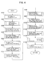
- FIG. 4 is a flow chart illustrating the procedure of the inter-vehicle distance maintenance control operation in controller 50 as an embodiment. This operation is performed consecutively once every prescribed interval, for example, 50 msec.
- the running state refers to information pertaining to the running state of the host vehicle including the state of the obstacle ahead of the host vehicle.
- the inter-vehicle distance to the obstacle ahead of the host vehicle and the direction of the obstacle ahead of the host vehicle, such as a preceding vehicle, detected by laser radar 10 and the host vehicle speed detected by vehicle speed sensor 20 are read.
- step S200 based on the running state data read and recognized in step S100, the state of the obstacle ahead of the host vehicle is recognized.
- the current relative position and its movement direction/movement speed of the obstacle with respect to the host vehicle are recognized. Then, it recognizes where the obstacle with respect to running of the host vehicle is set and how it moves in relation.
- step S300 as the value representing the confidence that the obstacle ahead of the host vehicle and as the object for the operation reaction force control and engine torque control will remain present as the control object ahead of the host vehicle, the confidence factor of the obstacle is computed.
- the confidence factor may also be taken as the value that represents the probability of the obstacle ahead of the host vehicle being present in the road to be travelled by the host vehicle (predicted running path).
- the predicted running path can be predicted based on the yaw rate detected by yaw rate sensor 30 and the host vehicle speed detected by vehicle speed sensor 20. In this case, when the predicted running path is determined, filtering is performed for the yaw rate detected by yaw rate sensor 30 such that there is no variation in the predicted running path due to small variations in the yaw rate.
- This filter can be realized by, for example, a low-pass filter.
- the response property slows. Consequently, for example, when the host vehicle changes lanes to pass the obstacle ahead of the host vehicle, the predicted running path determined based on the yaw rate cannot quickly respond to the motion of the host vehicle, especially turning of the steering wheel. As a result, it treats the obstacle ahead of the host vehicle to be passed as remaining in the predicted running path, so that the operation reaction force control and the engine torque control continues with the obstacle ahead of the host vehicle are taken as the object. As a result, the driver feels a braking-like discomfort when the host vehicle passes the obstacle ahead of the host vehicle.
- Embodiment 1 when the driver depresses accelerator pedal 72 to pass the obstacle ahead of the host vehicle, the cutoff frequency in the filtering with respect to the yaw rate detected by yaw rate sensor 30 is corrected, and the mode changes to light filtering. As a result, a predicted running path that corresponds swiftly to the steering wheel operation by the driver is sought.
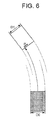
- Figure 6 is a schematic diagram illustrating the relative positional relationship between the host vehicle and an obstacle when it appears ahead of the host vehicle while the host vehicle travels a curve in the road. As shown in Figure 6 , when deviation occurs in the lateral direction between the center of the host vehicle and the center of the obstacle, this lateral deviation is computed as offset value ⁇ , and, from the computed lateral offset value ⁇ , the confidence factor is computed.
- step S301 whether accelerator pedal 72 is depressed down is detected.
- step S3011 by performing differential computation for accelerator pedal depression amount APO by the driver detected by accelerator pedal depression amount detecting part 73, and the depression speed of accelerator pedal 72, that is, accelerator opening speed dAPO, is computed.
- step S3012 it is determined whether the accelerator opening speed dAPO exceeds a prescribed accelerator opening speed threshold dAPO1
- dAPO ⁇ dAPO1 it is determined that the driver is depressing accelerator pedal 72, so that the process goes to step S3013 to set accelerator depression operation flag Flg_APO to 1.
- dAPO ⁇ dAPO1 it is determined that the driver is not stepping down accelerator pedal 72, that is, accelerator pedal 72 is maintained or reset, or accelerator pedal 72 is released, so that the process goes to step S3014, and accelerator depression operation flag Flg_APO is set at 0, that is, it is cleared.
- step S302 it is determined whether accelerator pedal 72 is depressed down based on the result of detection of the accelerator pedal depression operation in step S301.
- the process goes to step S308.
- the process goes to step S303.
- step S303 filtering is performed with respect to yaw rate ⁇ detected by yaw rate sensor 30, and yaw rate filter value ⁇ 1 is computed.
- yaw rate filter value ⁇ 1 can be computed using the following Formula 1 from cutoff frequency f1.
- ⁇ ⁇ 1 ⁇ ⁇ 2 ⁇ ⁇ f ⁇ 1 / S + 2 ⁇ ⁇ f ⁇ 1
- S represents a Laplace operator
- step 304 host vehicle speed V detected by vehicle speed sensor 20 is read.
- step S305 the turning radius (predicted turning radius) R of the predicted running path is computed from yaw rate filter value ⁇ 1 computed in step S303 and host vehicle speed V read in step S304.
- step S306 the position of the obstacle ahead of the host vehicle is computed.
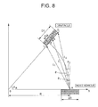
- the position of the center of the curved road is taken as O, and the central angle between the host vehicle and the obstacle is taken as ⁇ R.
- the position of the center of the host vehicle when the host vehicle reaches the current position of the obstacle is taken as E, and the distance between position E and obstacle center position B is taken as ⁇ .
- R represents the turning radius of the curved road, and the predicted turning radius computed in step S305 is adopted as is.
- obstacle width D1 can be computed using the following formula (Formula 12).
- D 1 2 L 1 2 + L 2 2 - 2 ⁇ L 1 ⁇ L 2 cos ⁇ 1 - ⁇ 2 ⁇
- D 1 L 1 2 + L 2 2 - 2 ⁇ L 1 ⁇ L 2 cos ⁇ 1 - ⁇ 2
- Obstacle width D1 can be used to compute distance L to the center of the obstacle using Formula (13).
- step S307 lateral offset value ⁇ between the host vehicle and the obstacle is computed. If the angle in the front-left direction of the host vehicle is positive, the offset value ⁇ can be computed by the following Formulas 16, 17.
- step S302 if it is determined that accelerator pedal 72 is depressed, the process goes to step S308, and the cutoff frequency is corrected to change the filtering with respect to yaw rate ⁇ detected by yaw rate sensor 30 to light filtering.
- cutoff frequency correction value f' is set based on inter-vehicle distance L between the host vehicle and the obstacle ahead of the host vehicle. By correcting the cutoff frequency in this way, it is possible to correct the confidence factor, which is to be explained later.
- Figure 9 is a diagram illustrating the relationship between inter-vehicle distance L and cutoff frequency correction value f'.
- cutoff frequency correction value f' is fixed at minimum value f1 to remove the noise and drift of the detected value of the yaw rate.
- minimum value f1 refers to the cutoff frequency adopted in the filtering performed when accelerator pedal 72 is depressed down.
- cutoff frequency correction value f' is gradually increased.
- cutoff frequency correction value f' is fixed at maximum value f2.
- cutoff frequency correction value f' computed in step S308 is used to compute yaw rate correction value ⁇ 2 after filtering (yaw rate filter correction value).
- the yaw rate correction value ⁇ 2 is computed using the following Formula 18.
- ⁇ ⁇ 2 ⁇ ⁇ 2 ⁇ ⁇ f ⁇ / S + 2 ⁇ ⁇ f ⁇
- step S310 host vehicle speed V detected by vehicle speed sensor 20 is read.
- step S311 predicted turning radius R is computed.
- predicted turning radius R can be computed using the following Formula 19 from yaw rate correction value ⁇ 2 computed in step S309 and host vehicle speed V.
- R V / ⁇ ⁇ 2
- step S312 Formulas 3-15 above are used to detect the position of the obstacle ahead of the host vehicle.
- step S313 Formulas 16 and 17 above are used to compute lateral offset value ⁇ between the host vehicle and the obstacle.
- step S314 lateral offset value ⁇ computed in step S307 or S313 is used to compute confidence factor Prob of the obstacle.
- Figure 10 is a diagram illustrating the relationship between the lateral offset value ⁇ and confidence factor Prob.
- a larger lateral offset value ⁇ means higher that there is a possibility that the obstacle ahead of the host vehicle will not remain as an obstacle ahead of the host vehicle. In this case, confidence factor Prob that the current obstacle ahead of the host vehicle will remain to be an object for control is gradually reduced.
- ⁇ > (DO/2 + D1/2) or ⁇ ⁇ (DO/2 - D1/2) the superposing amount between the host vehicle and the obstacle ahead of the host vehicle in the lateral direction disappears, and confidence factor Prob equals 0.
- step S400 the first inter-vehicle distance threshold with respect to the obstacle ahead of the host vehicle for use in the accelerator pedal reaction force control is computed.
- inter-vehicle distance threshold (steady-state value) Lh1* is computed.
- the inter-vehicle distance threshold (steady-state value) Lh1* corresponds to the inter-vehicle distance threshold when it is assumed that the vehicle speed of the obstacle, such as a preceding vehicle, is constant in the formula for computing the first inter-vehicle distance threshold for the obstacle ahead of the host vehicle.
- preceding vehicle speed Va is computed using Formula 20 based on host vehicle speed VSP and relative speed Vr.
- step S403 the following Formula 21 is used to compute acceleration/deceleration ⁇ a of the preceding vehicle.
- Aa d Va / dt
- step S404 it is determined whether parameter Tr1 for inter-vehicle distance threshold (transient value) for computing inter-vehicle distance threshold (transient value) Lr1* is computed/refreshed.
- prescribed level ⁇ 0 is a threshold for judging whether the preceding vehicle is decelerating, and it is preset to an appropriate value.
- the acceleration/deceleration ⁇ a of the preceding vehicle and deceleration judgment threshold ⁇ 0 are taken to have positive values in acceleration, and negative values in deceleration.
- step S406 when it is determined that the preceding vehicle is decelerating, the following formula (Formula 22) is used to compute and refresh parameter Tr1 for the inter-vehicle distance threshold (transient value).
- Tr1 the inter-vehicle distance threshold
- the parameter Tr1 for the inter-vehicle distance threshold represents the portion (L-Lh1*) corresponding to the tolerable distance of real inter-vehicle distance L with respect to inter-vehicle distance threshold (steady-state value) Lh1* when the preceding vehicle starts decelerating at a relative speed coefficient.
- step S408 the following formula (Formula 23) is used to compute inter-vehicle distance threshold (transient value) Lr1*.
- Lr ⁇ 1 * Tr ⁇ 1 ⁇ Vr
- inter-vehicle distance threshold (transient value) Lr1* corresponds to the inter-vehicle distance threshold when it is assumed that the obstacle ahead of the host vehicle, such as a preceding vehicle, is decelerating in the formula for computing the first inter-vehicle distance threshold.
- first inter-vehicle distance threshold L1* is computed using inter-vehicle distance threshold (steady-state value) Lh1* computed in step S401 and the inter-vehicle distance threshold computed in step S408.
- the following formula (Formula 24) is used to compute first inter-vehicle distance threshold L1* as the sum of the inter-vehicle distance threshold (steady-state value) Lh1* and the inter-vehicle distance threshold (transient value) Lr1*.
- L ⁇ 1 * Lh ⁇ 1 * + Lr ⁇ 1 *
- step S600 based on the first inter-vehicle distance threshold L1*, target accelerator pedal reaction force FA* for applying on accelerator pedal 72 is determined.
- difference (deviation in inter-vehicle distance) ⁇ L1 between first inter-vehicle distance threshold L1* and actual inter-vehicle distance L is computed using the following formula (Formula 25).
- ⁇ L ⁇ 1 L ⁇ 1 * - 1
- Kp represents the gain for computing target accelerator pedal reaction force FA* from inter-vehicle distance deviation ⁇ L1, and it is set based on confidence factor Prob of the obstacle computed in step S300.
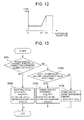
- Figure 12 is a diagram illustrating the relationship between confidence factor Prob and gain Kp. As shown in Figure 12 , a smaller confidence factor Prob, means lower a gain Kp.
- target accelerator pedal reaction force FA* is computed such that it is larger when actual inter-vehicle distance L decreases with respect to first inter-vehicle distance threshold L1*, and it is smaller when gain Kp computed based on confidence factor Prob is less.
- confidence factor Prob 1.
- confidence factor Prob 0.8.
- confidence factor Prob 0.6.
- step S600 target accelerator pedal reaction force FA* is computed in step S600. Then, the process goes to step S700. In step S700, it is determined whether the operator has further depressed accelerator pedal 72. In the following, an explanation will be given regarding the operation carried out in this case with reference to the flow chart shown in Figure 13 .
- step S703 it is determined whether accelerator pedal depression amount APO detected by accelerator pedal depression amount detecting part 73 is less than accelerator opening retention value Acch.
- accelerator pedal depression amount APO is less than accelerator opening retention value Acch, the process goes to step S704.
- accelerator pedal depression amount APO is greater than accelerator opening retention value Acch, the process goes to step S705.
- step S700 After determination of driver action in step S700, that is, after determination of whether the driver has depressed down accelerator pedal 72, the process goes to step S800.
- step S800 based on depression by the driver determined in step S700, target accelerator pedal reaction force FA* computed in step S600 is corrected.
- step S801 based on accelerator depression increment ⁇ Acc computed in step S700, target pedal reaction force correction coefficient K_fa for correcting target accelerator pedal reaction force FA* is computed according to the following formula (Formula 28).
- K_fa 100 - ⁇ Acc ⁇ Kacc
- Kacc is the gain for computing target pedal reaction force correction coefficient K_fa from accelerator depression increment ⁇ Acc, and it is set based on confidence factor Prob of the obstacle computed in step S300.
- Figure 15 is a diagram illustrating the relationship between confidence factor Prob and gain Kacc. As shown in Figure 15 , when confidence factor Prob approaches one, gain Kacc is set to the minimum value, such a the smaller confidence factor Prob results in a higher gain Kacc.
- the maximum value of target pedal reaction force correction coefficient K_fa is 100, and the minimum is 0.
- target accelerator pedal reaction force correction value FA*corr is computed by means of the following formula (Formula 29) from target pedal reaction force correction coefficient K_fa computed in step S801 and target accelerator pedal reaction force FA* computed in step S600.
- FA * corr K_fa ⁇ FA * / 100
- a smaller confidence factor Prob results in a larger gain Kacc, and larger correction amount of target accelerator pedal reaction force FA* with respect to accelerator depression increment ⁇ Acc. That is, in this case, target accelerator pedal reaction force correction value FA*corr decreases and accelerator pedal 72 can be depressed down more easily. Also, a larger accelerator depression increment ⁇ Acc results in a smaller target pedal reaction force correction coefficient K_fa, and smaller the target accelerator pedal reaction force correction value FA*corr.
- step S800 After target accelerator pedal reaction force correction value FA* corr is computed in step S800, the process goes to step S900.
- step S900 the second inter-vehicle distance threshold for the obstacle for the engine torque control is computed.
- the computing of the second inter-vehicle distance threshold with reference to the flow chart shown in Figure 16 .
- step S910 the slope of the road the host vehicle is travelling is determined.
- the torque amplification rate of the engine torque converter is Rt
- the automatic transmission gear ratio is Rat
- the differential gear ratio is Rdef
- the relationship between driving shaft torque Tw and engine torque Te can be represented by the following formula (Formula 3).
- Tw Rt ⁇ Rat ⁇ Rdef ⁇ Te
- ⁇ a represents the aerodynamic resistivity
- Sv represents the front projection area
- ⁇ r represents the rotary resistivity
- Mv represents weight of the vehicle
- g represents the acceleration of gravity
- VSP represents the host vehicle speed.
- s represents a Laplace operator
- Rw represents the coefficient used in computing the slope
- step S920 second inter-vehicle distance threshold L2* with respect to the obstacle ahead of the host vehicle is computed.
- L2* the second inter-vehicle distance threshold
- preceding-vehicle-speed-dependent reference distance Lh2* is computed.
- Figure 18 is a diagram illustrating the relationship between preceding vehicle speed Va and preceding-vehicle-speed-dependent reference distance Lh2*.
- the preceding-vehicle-speed-dependent reference distance Lh2* is set such that it is increased slowly from minimum value L2min so that a higher preceding vehicle speed Va means a farther distance at which the output amount of the engine torque with respect to accelerator pedal depression amount APO is controlled.
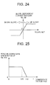
- slope-dependent correction time T_slp is computed based on slope SLP of the road the host vehicle is travelling.
- Figure 19 is a diagram illustrating the relationship between slope SLP and slope-dependent correction time T_slp.
- slope SLP when slope SLP is positive, that is, when the vehicle travels up a slope, slope-dependent correction time T_slp is set to a negative value.
- slope-dependent correction time T_slp when the slope SLP is negative, that is, when the vehicle travels down a slope, slope-dependent correction time T_slp is set to a positive value, such that a larger absolute value of the slope SLP means a larger absolute value of slope-dependent correction time T_slp.
- the absolute value of slope SLP exceeds a prescribed level, the absolute value of slope-dependent correction time T_slp is fixed at a prescribed value.
- step S924 second inter-vehicle distance threshold L2* is computed. From preceding-vehicle-speed-dependent reference distance Lh2* computed in step S921 and relative-speed-dependent correction distance Lr2* computed in step S923, second inter-vehicle distance threshold L2* is computed using the following formula (Formula 36).
- L ⁇ 2 * Lh ⁇ 2 * + Lr ⁇ 2 *
- step S920 After second inter-vehicle distance threshold L2* is computed in step S920, in step S930, inter-vehicle distance deviation ⁇ L2 is computed from actual inter-vehicle distance L and second inter-vehicle distance threshold L2*.
- ⁇ L2 inter-vehicle distance deviation
- step S931 When it is determined that L>L2* in step S931, the process goes to step S933, and inter-vehicle distance deviation ⁇ L2 is set to 0, that is, it is cleared.
- step S1000 after computing the second inter-vehicle distance threshold in step S900, the process goes to step S1000.
- step S1000 from second inter-vehicle distance threshold L2* computed in step S900 as well as inter-vehicle distance deviation ⁇ L2, target accelerator pedal opening final value APO0* for controlling the output amount of the engine torque with respect to accelerator pedal depression amount APO by the driver is computed.
- target accelerator pedal opening final value APO0* for controlling the output amount of the engine torque with respect to accelerator pedal depression amount APO by the driver is computed.
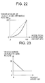
- step S1010 target accelerator opening minimum value APO_min with respect to accelerator pedal depression amount APO is computed.
- Figure 22 is a diagram illustrating the relationship between accelerator pedal depression amount APO and target accelerator opening minimum value APO_min. As indicated by the solid line in Figure 22 , the target accelerator opening minimum value APO_min is set such that it is determined uniquely with respect to accelerator pedal depression amount APO; a larger accelerator pedal depression amount APO means a larger target accelerator opening minimum value APO_min.
- step S1020 torque down gain Ka0 is computed using the following formula (Formula 38) from vehicle-speed-dependent gain K v and inter-vehicle distance deviation ⁇ L2 computed in step S930 and inter-vehicle distance deviation ⁇ L2.
- Ka ⁇ 0 100 - ⁇ L ⁇ 2 ⁇ Kv
- vehicle-speed-dependent gain Kv is the amount of change of torque down gain Ka0 with respect to inter-vehicle distance deviation ⁇ L2, and it is computed from the plot shown in Figure 23 .
- the vehicle-speed-dependent gain Kv gradually decreases, so that the amount of change of torque down gain Ka0 with respect to inter-vehicle distance deviation ⁇ L2 is decreased.
- vehicle-speed-dependent gain Kv is fixed at a prescribed value.
- step S1030 torque down gain Ka0 computed in step S1020 is corrected corresponding to slope SLP of the road the host vehicle is travelling.
- slope-dependent corrected gain Ka_slp is computed.
- slope SLP is positive, that is, when the vehicle travels up a slope
- slope-dependent corrected gain Ka_slp is set to a positive value.
- slope SLP is negative, that is, when the vehicle travels down a slope
- slope-dependent corrected gain Ka_slp is set to a negative value.
- a larger absolute value of slope SLP means a larger absolute value of slope-dependent corrected gain Ka_slp.
- the absolute value of slope SLP exceeds a prescribed level, the absolute value of slope-dependent corrected gain Ka_slp is fixed at a prescribed value.
- torque down gain Ka1 has a maximum value of 100 and minimum value of 0.
- step S1040 based on confidence factor Prob computed in step S300, torque down gain Ka1 computed in step S1030 is corrected.
- torque down gain minimum value Ka_min is computed corresponding to confidence factor Prob.
- a smaller confidence factor Prob of the obstacle means a larger torque down gain minimum value Ka_min.
- final torque down gain Ka is computed. More specifically, by means of select a high torque down gain Ka1 and torque down gain minimum value Ka_min as shown in the following (Formula 40), torque down gain Ka is computed.
- Ka max Ka ⁇ 1 , Ka_min
- target accelerator pedal opening final value APO0* is computed. As shown in the following formula (Formula 41), target accelerator pedal opening final value APO0* is computed by interior-dividing target accelerator opening minimum value APO_min computed in step S1010 and accelerator pedal depression amount APO of the driver in torque down gain Ka computed in step S1040.
- APO ⁇ 0 * APO ⁇ Ka 100 + APO _min ⁇ 100 - Ka 100
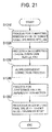
- step S1100 the operation for detecting the accelerator pedal depression operation is carried out.
- an explanation will be given regarding the operation carried out in step S1100 with reference to the flow chart shown in Figure 26 .
- step S1101 by differential computation for accelerator pedal step-down amount APO by the driver detected by accelerator pedal step-down amount detecting part 73, the depression speed of accelerator pedal 72, that is, accelerator pedal opening speed dAPO, is computed.
- step S1102 it is determined whether an obstacle exists ahead of the host vehicle.
- accelerator opening speed threshold dAP01 computed based on confidence factor Prob is set in accelerator opening speed threshold dAPO0 as the threshold for judging the depression operation of accelerator pedal 72.
- Figure 27 is a diagram illustrating the relationship between confidence factor Prob of the obstacle and accelerator opening speed threshold dAPO1 As shown in Figure 27 , the larger the confidence factor Prob, the larger accelerator opening speed threshold dAPO1 When confidence factor Prob is smaller, accelerator opening speed threshold dAPO1 is set smaller. Consequently, the smaller the confidence factor Prob of the obstacle, the earlier the depression by the driver on the accelerator pedal can be detected.
- step S1102 When it is determined that no obstacle exists ahead of the host vehicle in step S1102, the process goes to step 1104, and preset value dAPO2 is set as accelerator opening speed threshold dAPO0
- value dAPO2 when there no obstacle exists ahead of the host vehicle corresponds to the minimum value of accelerator opening speed threshold dAPO1 in the plot of confidence factor Prob and accelerator opening speed threshold dAPO1 shown in Figure 27 .
- step S1105 it is determined whether accelerator opening speed dAPO computed in step S1101 exceeds accelerator opening speed threshold dAPO0 set in step S1103 or S1104. If dAPO ⁇ dAPO0, it is determined that accelerator pedal 72 is depressed down, and the process goes to step S1106, and accelerator step-down operation flag Flg-APO is set to 1. On the other hand, when dAPO ⁇ dAPO0, it is determined that the driver is not stepping down accelerator pedal 72, that is, accelerator pedal 72 is maintained or reset, or accelerator pedal 72 is released. Then, the process goes to step S1107, and accelerator step-down operation flag Flg-APO is set to 0, that is, it is cleared.
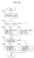
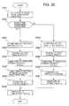
- step S1200 the target accelerator opening is reset.
- step S1201 it is determined whether an obstacle exists ahead of the host vehicle.
- the process goes to step S1202, and it is determined whether torque down gain Ka computed in step S1040 is smaller than the previous-cycle value of the torque down gain output value Ka_out_z. If Ka ⁇ Ka_out_z, the process goes to step S1203, and the change rate limiter for torque down gain Ka is set.
- limiter Ka_up for increasing torque down gain Ka and limiter Ka_dn for decreasing it are set, respectively.
- limiter Ka_up for increasing the torque down gain is set to zero
- limiter Ka_dn for decreasing the torque down gain are set to preset value Ka_dn1.
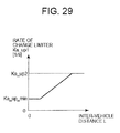
- step S1205 as limiter Ka_up for increasing the torque down gain, value Ka_up1 is set based on inter-vehicle distance L between the host vehicle and the obstacle ahead of the host vehicle, while limiter Ka_dn for decreasing the torque down gain is set to zero.
- Figure 29 is a diagram illustrating the relationship between inter-vehicle distance L and limiter Ka_up1 for increasing the torque down gain. As shown in Figure 29 , with the minimum value of Ka_up_min and the maximum value of Ka_up2, the limiter Ka_up1 for increasing the torque down gain is set such that it is increased slowly as inter-vehicle distance L increases.
- step S1210 the change rate limiter process is performed using limiter Ka_up for increasing the torque down gain and limiter Ka_dn for decreasing the torque down gain for torque down gain Ka computed in step S1040 to compute torque down gain output value Ka_out.
- step S1211 based on torque down gain output value Ka_out computed in step S1210, target accelerator opening APO* for use as the instruction value to engine controller 74 is computed.
- step S1300 target accelerator pedal opening APO* computed in step S1200 is output to engine controller 74, and, at the same time, target accelerator pedal reaction force correction value FA*corr computed in step S800 is output to accelerator pedal reaction force controller 70.
- Engine controller 74 controls the engine torque generation amount according to target accelerator opening APO* to perform engine torque control.
- Accelerator pedal reaction force controller 70 controls the accelerator pedal depression reaction force generated on accelerator pedal 72 corresponding to the target accelerator pedal reaction force correction value FA*corr. At this point, the current cycle ends.
- Embodiment 2 of the present invention.
- the basic configuration of the inter-vehicle distance maintenance supporting system in Embodiment 2 is the same as that of Embodiment 1 above.
- an explanation will be given mainly regarding the points of difference from Embodiment 1 above.
- Embodiment 2 the future position of the obstacle ahead of the host vehicle with respect to the host vehicle is predicted, and the predicted position of the obstacle ahead of the host vehicle is used to compute confidence factor Prob.
- prediction time t indicating the time in seconds to be predicted for the future position is set using inter-vehicle distance L between the host vehicle and the obstacle ahead of the host vehicle.
- Step S300 of the flow chart shown in Figure 4 This is executed in step S300 of the flow chart shown in Figure 4 .
- Steps S301-S307 are the same as that shown in the flow chart of Figure 5 , so an explanation is omitted.
- step S321 Formula 1 above is used to compute yaw rate filter value ⁇ 1.
- step S322 host vehicle speed V is read, and, in step S323, predicted turning radius R is computed from Formula 2 above.
- step S324 the position of the obstacle ahead of the host vehicle after prediction time t is computed.
- Figure 31 shows the relationship between inter-vehicle distance L and prediction time t.
- inter-vehicle distance L is greater than prescribed inter-vehicle distance L1
- prediction time t is gradually increased.
- prediction time t is fixed at the maximum value t1.
- D1 represents the inter-vehicle distance between the host vehicle and the obstacle ahead of the host vehicle at the present time
- X1 represents the lateral position of the obstacle ahead of the host vehicle with respect to the host vehicle.
- inter-vehicle distance D1 and lateral position X1 correspond to distance L and offset value ⁇ in Figure 8 , respectively.
- the position of the obstacle ahead of the host vehicle at prediction time t later has the longitudinal position (inter-vehicle distance) of (D1 + t x vVy) and the lateral position (offset value) of (X1 + t x vVx).
- step S325 the position of the obstacle ahead of the host vehicle after the prediction time computed in step S324 is used to compute offset value ⁇ , and, in step S326, confidence factor Prob is computed.
- accelerator pedal step-down amount APO of accelerator pedal 72 may be used, and a greater the accelerator pedal step-down amount APO, a greater prediction time t is set.
- Embodiment 3 The basic configuration of the inter-vehicle distance maintenance supporting system in Embodiment 3 is the same as that in Embodiment 1. In the following, an explanation will be given mainly on the points of difference from Embodiment 1.
- Embodiment 1 by changing the response of filtering with respect to yaw rate ⁇ detected by yaw rate sensor 30, confidence factor Prob is decreased in an earlier stage when passing the obstacle ahead of the host vehicle. In Embodiment 3, confidence factor Prob computed based on offset value ⁇ is directly corrected.
- step S331 the above formula (Formula 1) is used to compute yaw rate filter value ⁇ 1.
- step S332 host vehicle speed V is read.
- step S333 predicted turning radius R is computed from the above formula (Formula 2).
- step S334 the Formulas 3-15 are used to compute the position of the obstacle ahead of the host vehicle.
- step S335, Formulas 16 and 17 are used to compute offset value ⁇ .
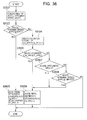
- step S336 the confidence factor correction coefficient for correcting the confidence factor is computed. More specifically, the slope of the confidence factor computing formula (confidence factor correction coefficient) is changed to correspond to inter-vehicle distance L between the host vehicle and the obstacle ahead of the host vehicle, and the formula for computing confidence factor Prob is changed. In the following, an explanation will be given regarding this case with reference to the flow chart shown in Figure 34 .
- step S3361 preset constant Da and confidence factor change amount ⁇ Prob are used to set the first confidence factor computing formula represented by the following formula (Formula 44).
- ProbA 1 - ⁇ Prob ⁇ ⁇ / Da
- step S3362 preset constant Db and confidence factor change amount ⁇ Prob are used to set the second confidence factor computing formula represented by the following formula (Formula 45).
- ProbB 1 - ⁇ Prob ⁇ ⁇ / Db
- Figure 35 is a diagram illustrating the relationship between the confidence factors ProbA, ProbB and offset value ⁇ . As shown in Figure 35 , when the absolute value of offset value ⁇ is increased, the confidence factors ProbA, ProbB are gradually reduced from 1. Here, the slope of confidence factor ProbB is set steeper than that of confidence factor ProbA.
- step S3365 If the judgment result in step S3365 is NO, the process goes to step S3367, and Formula 46 is used to set the confidence factor computing formula.
- Prob ProbB ⁇ L - L ⁇ 2 / L ⁇ 1 - L ⁇ 2 + ProbB ⁇ L ⁇ 1 - L / L ⁇ 1 - L ⁇ 2
- Formula 46 is for interior-dividing confidence factor ProbA and confidence factor ProbB in inter-vehicle distance L, and it corresponds to the intermediate region between ProbA and ProbB shown in Figure 35 .
- the prescribed inter-vehicle distances L1, L2 are preset to appropriate values.
- the first inter-vehicle distance threshold L1* and second inter-vehicle distance threshold L2* may also be used as the prescribed inter-vehicle distances L1, L2, respectively.
- step S337 confidence factor Prob is computed using the computing formula determined in step S336. Also, when it is determined in step S302 that accelerator pedal 72 is not depressed, the first confidence factor computing formula as Formula 44 is used to compute confidence factor Prob.
- Embodiment 4 of the inter-vehicle distance maintenance supporting system of the present invention.
- the basic configuration of Embodiment 4 is the same as that of Embodiment 1. Consequently, in the following, an explanation will be given mainly regarding the points of difference from Embodiment 1.
- Embodiment 1 when accelerator pedal 72 is depressed, the filtering for yaw rate ⁇ is changed to a light filtering.
- the operator may lift accelerator pedal 72 before the host vehicle has fully passed the obstacle ahead of the host vehicle, that is, before the current obstacle ahead of the host vehicle is fully cancelled as an object for control. Consequently, in Embodiment 4, even after accelerator pedal 72 is no longer depressed, the light filtering is continued to compute confidence factor Prob for a prescribed time, so that the obstacle ahead of the host vehicle is reliably cancelled as an object for control.
- step S301 of the flow chart of the confidence factor computing shown in Figure 5 This is executed in step S301 of the flow chart of the confidence factor computing shown in Figure 5 .
- step S3021 accelerator opening speed dAPO is computed.
- step S3022 it is determined whether accelerator opening speed dAPO exceeds accelerator opening speed threshold dAPO1 that has been preset. If dAPO ⁇ dAPO1 the process goes to step S3023, and accelerator step-down operation flag Flg_APO is set to 1. In addition, delay counter Cnt_APO is set to 0.
- step S3022 if it is found that dAPO ⁇ dAPO1 it is determined that the driver is not depressing accelerator pedal 72, that is, accelerator pedal 72 is held constant or reset, or accelerator pedal 72 is released. It then goes to step S3024, and delay counter Cnt_APO is counted up. In step S3025, it is determined whether delay counter Cnt_APO exceeds a preset time T_APO (say, 1 sec). If delay counter Cnt_APO is greater than prescribed time T_APO, the process goes to step S3026, and accelerator step-down operation flag Flg_APO is set to 0, that is, it is cleared.
- T_APO preset time
- step S3027 it is determined whether accelerator pedal step-down amount APO is zero. If accelerator pedal step-down amount APO is zero, it is determined that the driver has lifted his foot from accelerator pedal 72, and it then goes to step S3026. Then, accelerator step-down operation flag Flg_APO is set to 0, that is, it is cleared.
- step S3027 if it is determined that accelerator pedal step-down amount APO is non-zero, the process goes to step S3028, and it is determined whether accelerator opening speed dAPO is less than preset accelerator opening speed threshold dAPO2. If accelerator opening speed dAPO is less than preset accelerator opening speed threshold dAPO2, it is determined that the driver is resetting accelerator pedal 72 at a speed higher than the prescribed operation speed, so that the process goes to step S3026, and accelerator step-down operation flag Flg_APO is set to zero, that is, it is cleared. Also, accelerator opening speed dAPO has a positive value when accelerator pedal 72 is depressed, and it has a negative value when accelerator pedal 72 is reset.
- step S3028 when it is determined that accelerator opening speed dAPO is greater than preset accelerator opening speed threshold dAPO2, it is determined that the driver is resetting accelerator pedal 72 at a speed lower than a prescribed speed, or the driver is keeping the depression amount of accelerator pedal 72 nearly constant. It is finished as is.
- detecting of the depression operation of accelerator pedal 72 may be performed along with Embodiment 2 or 3.
- Embodiment 4 in addition to the effects of Embodiments 1-3, the following operation effects can be displayed.
- Embodiments 1-4 the device that perform control of the accelerator pedal reaction force and control of the engine torque has been explained based on inter-vehicle distance L between the host vehicle and the obstacle ahead of the host vehicle.
- the present invention is not limited to this case.
- One may also adopt a scheme in which correction of the confidence factor is performed in a device that controls only the accelerator pedal reaction force corresponding to inter-vehicle distance L.
- correction is performed on target accelerator pedal reaction force FA* and target accelerator opening APO* corresponding to confidence factor Prob.
- the configuration may also be such that only one of them is corrected.
- Figure 9 is a diagram illustrating the relationship between inter-vehicle distance L and cutoff frequency correction value f'.
- Figure 31 shows the relationship between inter-vehicle distance L and prediction time t. It may be set such that the shorter the inter-vehicle distance L, the larger the cutoff frequency correction value f' or the longer the prediction time t, and it is not restricted to the characteristics shown in Figure 9 or 31 .
- laser radar 10 and yaw rate sensor 30 function as obstacle detecting means; laser radar 10 functions as the inter-vehicle distance detecting means; accelerator pedal reaction force controller 70 functions as the accelerator pedal reaction force control means; and confidence factor computing part 52 functions as the confidence factor computing means and the confidence factor correcting means.
- confidence factor computing part 52 can function as the confidence factor computing means and the confidence factor correcting means even when accelerator pedal 72 is not depressed down.
- Yaw rate sensor 30 functions as the yaw rate detecting means; accelerator pedal step-down operation detecting part 60 functions as the accelerator pedal depression detecting means, and accelerator pedal reaction force correcting part 56 can function as the accelerator pedal reaction force correcting means.
- the present invention is not limited to the aforementioned scheme.
- the obstacle detecting means instead of laser radar 10, one may make use of a millimetre wave radar as another scheme, and the state of the obstacle can also be detected by inter-vehicle communication or the like.
- a millimetre wave radar as another scheme, and the state of the obstacle can also be detected by inter-vehicle communication or the like.
Landscapes
- Engineering & Computer Science (AREA)
- Transportation (AREA)
- Mechanical Engineering (AREA)
- Automation & Control Theory (AREA)
- Human Computer Interaction (AREA)
- Chemical & Material Sciences (AREA)
- Combustion & Propulsion (AREA)
- Control Of Driving Devices And Active Controlling Of Vehicle (AREA)
- Traffic Control Systems (AREA)
- Length Measuring Devices By Optical Means (AREA)
Applications Claiming Priority (2)
| Application Number | Priority Date | Filing Date | Title |
|---|---|---|---|
| JP2007327068 | 2007-12-19 | ||
| JP2008205852A JP5309778B2 (ja) | 2007-12-19 | 2008-08-08 | 車間維持支援装置および車間維持支援方法 |
Publications (3)
| Publication Number | Publication Date |
|---|---|
| EP2072316A2 true EP2072316A2 (de) | 2009-06-24 |
| EP2072316A3 EP2072316A3 (de) | 2010-12-15 |
| EP2072316B1 EP2072316B1 (de) | 2016-08-31 |
Family
ID=40254447
Family Applications (1)
| Application Number | Title | Priority Date | Filing Date |
|---|---|---|---|
| EP08172058.3A Not-in-force EP2072316B1 (de) | 2007-12-19 | 2008-12-18 | System und Verfahren zur Unterstützung beim Einhalten eines Abstands zwischen Fahrzeugen |
Country Status (2)
| Country | Link |
|---|---|
| US (1) | US8996294B2 (de) |
| EP (1) | EP2072316B1 (de) |
Cited By (7)
| Publication number | Priority date | Publication date | Assignee | Title |
|---|---|---|---|---|
| WO2014039200A1 (en) * | 2012-09-05 | 2014-03-13 | Google Inc. | Construction zone detection using a plurality of information sources |
| US8996228B1 (en) | 2012-09-05 | 2015-03-31 | Google Inc. | Construction zone object detection using light detection and ranging |
| CN104554214A (zh) * | 2015-01-23 | 2015-04-29 | 无锡卓信信息科技有限公司 | 根据交通灯状态控制电动交通工具运行的系统及方法 |
| US9056395B1 (en) | 2012-09-05 | 2015-06-16 | Google Inc. | Construction zone sign detection using light detection and ranging |
| US9195914B2 (en) | 2012-09-05 | 2015-11-24 | Google Inc. | Construction zone sign detection |
| WO2016122383A1 (en) * | 2015-01-28 | 2016-08-04 | Scania Cv Ab | Method and control unit for adjusting a time gap |
| EP3279050A1 (de) * | 2016-08-01 | 2018-02-07 | Lucas Automotive GmbH | Steuerungs-system und steuerungs-verfahren zur auswahl und verfolgung eines kraftfahrzeugs |
Families Citing this family (17)
| Publication number | Priority date | Publication date | Assignee | Title |
|---|---|---|---|---|
| WO2011125168A1 (ja) * | 2010-04-05 | 2011-10-13 | トヨタ自動車株式会社 | 車両の衝突判定装置 |
| US8948954B1 (en) * | 2012-03-15 | 2015-02-03 | Google Inc. | Modifying vehicle behavior based on confidence in lane estimation |
| US9063548B1 (en) | 2012-12-19 | 2015-06-23 | Google Inc. | Use of previous detections for lane marker detection |
| US9081385B1 (en) | 2012-12-21 | 2015-07-14 | Google Inc. | Lane boundary detection using images |
| JP5852036B2 (ja) * | 2013-03-27 | 2016-02-03 | 株式会社日本自動車部品総合研究所 | 車載装置 |
| JP6237580B2 (ja) * | 2014-11-13 | 2017-11-29 | 株式会社デンソー | モータ制御装置 |
| MX358047B (es) | 2015-01-05 | 2018-08-03 | Nissan Motor | Dispositivo de generacion de ruta objetivo y dispositivo de control de conduccion. |
| CA2973111C (en) | 2015-01-05 | 2019-09-10 | Nissan Motor Co., Ltd. | Target vehicle speed generation device and drive control device |
| US20160297438A1 (en) * | 2015-04-13 | 2016-10-13 | Mando Corporation | Active cruise control system in vehicle and method thereof |
| JP6436116B2 (ja) * | 2016-03-08 | 2018-12-12 | トヨタ自動車株式会社 | 運転支援装置 |
| JP6773215B2 (ja) * | 2017-04-14 | 2020-10-21 | 日産自動車株式会社 | 車両制御方法及び車両制御装置 |
| US20180354362A1 (en) * | 2017-06-09 | 2018-12-13 | Honda Motor Co., Ltd. | Vehicle accelerator pedal force system, and methods of use and manufacture thereof |
| US10683002B2 (en) | 2017-06-27 | 2020-06-16 | Toyota Motor Engineering & Manufacturing North America, Inc. | Efficient acceleration from surrounding vehicles |
| KR102496654B1 (ko) * | 2018-02-21 | 2023-02-07 | 현대자동차주식회사 | 차량의 주행모드 전환 제어 장치 및 방법, 그리고 차량 시스템 |
| JP7151566B2 (ja) * | 2019-03-14 | 2022-10-12 | トヨタ自動車株式会社 | 車両走行制御装置 |
| US11623640B2 (en) | 2021-02-22 | 2023-04-11 | Ford Global Technologies, Llc | Methods and systems for assistive action of a vehicle |
| US11398153B1 (en) * | 2021-03-02 | 2022-07-26 | Here Global B.V. | System and method for determining a driving direction |
Citations (3)
| Publication number | Priority date | Publication date | Assignee | Title |
|---|---|---|---|---|
| JP2004249891A (ja) | 2003-02-21 | 2004-09-09 | Nissan Motor Co Ltd | 車両用運転操作補助装置およびその装置を備える車両 |
| JP2007327068A (ja) | 1997-03-25 | 2007-12-20 | Huntsman Internatl Llc | 軟質ポリウレタン発泡体の製造用プレポリマー組成物 |
| JP2008205852A (ja) | 2007-02-20 | 2008-09-04 | Canon Inc | 撮像装置 |
Family Cites Families (18)
| Publication number | Priority date | Publication date | Assignee | Title |
|---|---|---|---|---|
| JPS5733048A (en) * | 1980-08-04 | 1982-02-23 | Honda Motor Co Ltd | Throttle reaction control device of car |
| DE4314827A1 (de) * | 1993-05-05 | 1994-11-10 | Porsche Ag | Verfahren zur Bestimmung der Gierwinkelgeschwindigkeit eines Fahrzeuges |
| JP3330313B2 (ja) * | 1997-12-12 | 2002-09-30 | 本田技研工業株式会社 | 物体検知手段を備える車両の制御装置 |
| US6268803B1 (en) * | 1998-08-06 | 2001-07-31 | Altra Technologies Incorporated | System and method of avoiding collisions |
| JP3864406B2 (ja) * | 1999-01-26 | 2006-12-27 | マツダ株式会社 | 車両の表示装置 |
| DE10149146A1 (de) * | 2001-10-05 | 2003-04-17 | Bosch Gmbh Robert | Geschwindigkeitsregler mit Abstandsregelfunktion |
| US7039551B2 (en) * | 2002-02-04 | 2006-05-02 | Hrl Laboratories, Llc | Method and apparatus for calculating an operator distraction level |
| US6577947B1 (en) * | 2002-03-01 | 2003-06-10 | Rockwell Collins, Inc. | Method and apparatus for identification of hazards along an intended travel route |
| US7821422B2 (en) * | 2003-08-18 | 2010-10-26 | Light Vision Systems, Inc. | Traffic light signal system using radar-based target detection and tracking |
| DE10343174A1 (de) * | 2003-09-18 | 2005-04-14 | Robert Bosch Gmbh | Vorrichtung und Verfahren zur Regelung der Geschwindigkeit eines Fahrzeugs beim Rangieren/Einparken des Fahrzeugs |
| JP4229051B2 (ja) | 2004-11-26 | 2009-02-25 | 日産自動車株式会社 | 運転意図推定装置、車両用運転操作補助装置および車両用運転操作補助装置を備えた車両 |
| JP4114682B2 (ja) * | 2005-07-14 | 2008-07-09 | 日産自動車株式会社 | 車両用運転操作補助装置および車両用運転操作補助装置を備えた車両 |
| JP4788611B2 (ja) * | 2006-03-10 | 2011-10-05 | 日産自動車株式会社 | 車間維持支援装置および車間維持支援方法 |
| JP4434179B2 (ja) * | 2006-06-28 | 2010-03-17 | 日産自動車株式会社 | 車両用運転操作補助装置および車両用運転操作補助装置を備えた車両 |
| JP4254821B2 (ja) * | 2006-08-15 | 2009-04-15 | トヨタ自動車株式会社 | 制動制御装置 |
| JP4648282B2 (ja) * | 2006-10-06 | 2011-03-09 | 本田技研工業株式会社 | 車両用走行制御装置 |
| JP2008191781A (ja) * | 2007-02-01 | 2008-08-21 | Hitachi Ltd | 衝突回避システム |
| JP4759547B2 (ja) * | 2007-09-27 | 2011-08-31 | 日立オートモティブシステムズ株式会社 | 走行支援装置 |
-
2008
- 2008-12-17 US US12/337,397 patent/US8996294B2/en not_active Expired - Fee Related
- 2008-12-18 EP EP08172058.3A patent/EP2072316B1/de not_active Not-in-force
Patent Citations (3)
| Publication number | Priority date | Publication date | Assignee | Title |
|---|---|---|---|---|
| JP2007327068A (ja) | 1997-03-25 | 2007-12-20 | Huntsman Internatl Llc | 軟質ポリウレタン発泡体の製造用プレポリマー組成物 |
| JP2004249891A (ja) | 2003-02-21 | 2004-09-09 | Nissan Motor Co Ltd | 車両用運転操作補助装置およびその装置を備える車両 |
| JP2008205852A (ja) | 2007-02-20 | 2008-09-04 | Canon Inc | 撮像装置 |
Cited By (16)
| Publication number | Priority date | Publication date | Assignee | Title |
|---|---|---|---|---|
| USRE48322E1 (en) | 2012-09-05 | 2020-11-24 | Waymo Llc | Construction zone sign detection |
| US8996228B1 (en) | 2012-09-05 | 2015-03-31 | Google Inc. | Construction zone object detection using light detection and ranging |
| US9056395B1 (en) | 2012-09-05 | 2015-06-16 | Google Inc. | Construction zone sign detection using light detection and ranging |
| US9193355B2 (en) | 2012-09-05 | 2015-11-24 | Google Inc. | Construction zone sign detection using light detection and ranging |
| US9195914B2 (en) | 2012-09-05 | 2015-11-24 | Google Inc. | Construction zone sign detection |
| US9199641B2 (en) | 2012-09-05 | 2015-12-01 | Google Inc. | Construction zone object detection using light detection and ranging |
| US9221461B2 (en) | 2012-09-05 | 2015-12-29 | Google Inc. | Construction zone detection using a plurality of information sources |
| WO2014039200A1 (en) * | 2012-09-05 | 2014-03-13 | Google Inc. | Construction zone detection using a plurality of information sources |
| US9489601B2 (en) | 2012-09-05 | 2016-11-08 | X Development Llc | Construction zone sign detection |
| CN104554214A (zh) * | 2015-01-23 | 2015-04-29 | 无锡卓信信息科技有限公司 | 根据交通灯状态控制电动交通工具运行的系统及方法 |
| CN104554214B (zh) * | 2015-01-23 | 2017-12-05 | 无锡卓信信息科技有限公司 | 根据交通灯状态控制电动交通工具运行的系统及方法 |
| WO2016122383A1 (en) * | 2015-01-28 | 2016-08-04 | Scania Cv Ab | Method and control unit for adjusting a time gap |
| US10293821B2 (en) | 2015-01-28 | 2019-05-21 | Scania Cv Ab | Method and control unit for adjusting a time gap |
| CN107672595A (zh) * | 2016-08-01 | 2018-02-09 | 卢卡斯汽车股份有限公司 | 用于选择和跟踪机动车辆的控制系统和控制方法 |
| EP3279050A1 (de) * | 2016-08-01 | 2018-02-07 | Lucas Automotive GmbH | Steuerungs-system und steuerungs-verfahren zur auswahl und verfolgung eines kraftfahrzeugs |
| CN107672595B (zh) * | 2016-08-01 | 2022-04-15 | 采埃孚主动安全股份有限公司 | 用于选择和跟踪机动车辆的控制系统和控制方法 |
Also Published As
| Publication number | Publication date |
|---|---|
| EP2072316A3 (de) | 2010-12-15 |
| US8996294B2 (en) | 2015-03-31 |
| US20090164080A1 (en) | 2009-06-25 |
| EP2072316B1 (de) | 2016-08-31 |
Similar Documents
| Publication | Publication Date | Title |
|---|---|---|
| EP2072316B1 (de) | System und Verfahren zur Unterstützung beim Einhalten eines Abstands zwischen Fahrzeugen | |
| EP2072317B1 (de) | System und Verfahren zur Unterstützung beim Einhalten eines Abstands zwischen Fahrzeugen | |
| JP3197307B2 (ja) | 移動車の走行制御装置 | |
| US9771070B2 (en) | Method and system for controlling a host vehicle | |
| JP5056220B2 (ja) | 走行制御装置 | |
| EP1908660B1 (de) | Steuerungsvorrichtung für Hindernisvermeidung | |
| EP3663153A1 (de) | Fahrzeugsteuerungsvorrichtung | |
| US20090143951A1 (en) | Forward Collision Avoidance Assistance System | |
| US8103424B2 (en) | Inter-vehicle distance control apparatus and method for controlling inter-vehicle distance | |
| EP2712780B1 (de) | Verfahren und Vorrichtung zur Fahrunterstützung | |
| WO2019159725A1 (ja) | 車両制御装置 | |
| US20200353918A1 (en) | Vehicle control device | |
| JP6647681B2 (ja) | 車両制御装置 | |
| EP1720726A1 (de) | Verfahren und system zur unterstützung eines fahrzeugfahrers, der ein auf einer strasse fahrendes fahrzeug betätigt | |
| JP5772651B2 (ja) | 運転支援装置 | |
| JP7408458B2 (ja) | 走行経路生成システム及び車両運転支援システム | |
| JP6572949B2 (ja) | 車両制御装置 | |
| JP5380951B2 (ja) | 車間維持支援装置および車間維持支援方法 | |
| JP5309778B2 (ja) | 車間維持支援装置および車間維持支援方法 | |
| JP2021160659A (ja) | 車両制御装置 | |
| JP4973086B2 (ja) | 車両用運転支援装置および方法 | |
| JP7054047B2 (ja) | 車両制御装置 | |
| JP7185191B2 (ja) | 車両制御装置 | |
| JP7186952B2 (ja) | 車両制御装置 | |
| JP4349066B2 (ja) | 車両用運転操作補助装置および車両用運転操作補助装置を備えた車両 |
Legal Events
| Date | Code | Title | Description |
|---|---|---|---|
| PUAI | Public reference made under article 153(3) epc to a published international application that has entered the european phase |
Free format text: ORIGINAL CODE: 0009012 |
|
| AK | Designated contracting states |
Kind code of ref document: A2 Designated state(s): AT BE BG CH CY CZ DE DK EE ES FI FR GB GR HR HU IE IS IT LI LT LU LV MC MT NL NO PL PT RO SE SI SK TR |
|
| AX | Request for extension of the european patent |
Extension state: AL BA MK RS |
|
| PUAL | Search report despatched |
Free format text: ORIGINAL CODE: 0009013 |
|
| AK | Designated contracting states |
Kind code of ref document: A3 Designated state(s): AT BE BG CH CY CZ DE DK EE ES FI FR GB GR HR HU IE IS IT LI LT LU LV MC MT NL NO PL PT RO SE SI SK TR |
|
| AX | Request for extension of the european patent |
Extension state: AL BA MK RS |
|
| 17P | Request for examination filed |
Effective date: 20110606 |
|
| AKX | Designation fees paid |
Designated state(s): DE FR GB |
|
| 17Q | First examination report despatched |
Effective date: 20110825 |
|
| GRAP | Despatch of communication of intention to grant a patent |
Free format text: ORIGINAL CODE: EPIDOSNIGR1 |
|
| INTG | Intention to grant announced |
Effective date: 20160527 |
|
| RIN1 | Information on inventor provided before grant (corrected) |
Inventor name: KURATA, KAZUNORI Inventor name: ETORI, NARIAKI |
|
| GRAS | Grant fee paid |
Free format text: ORIGINAL CODE: EPIDOSNIGR3 |
|
| GRAA | (expected) grant |
Free format text: ORIGINAL CODE: 0009210 |
|
| AK | Designated contracting states |
Kind code of ref document: B1 Designated state(s): DE FR GB |
|
| REG | Reference to a national code |
Ref country code: GB Ref legal event code: FG4D |
|
| REG | Reference to a national code |
Ref country code: DE Ref legal event code: R096 Ref document number: 602008045966 Country of ref document: DE |
|
| REG | Reference to a national code |
Ref country code: FR Ref legal event code: PLFP Year of fee payment: 9 |
|
| REG | Reference to a national code |
Ref country code: DE Ref legal event code: R097 Ref document number: 602008045966 Country of ref document: DE |
|
| PLBE | No opposition filed within time limit |
Free format text: ORIGINAL CODE: 0009261 |
|
| STAA | Information on the status of an ep patent application or granted ep patent |
Free format text: STATUS: NO OPPOSITION FILED WITHIN TIME LIMIT |
|
| 26N | No opposition filed |
Effective date: 20170601 |
|
| REG | Reference to a national code |
Ref country code: FR Ref legal event code: PLFP Year of fee payment: 10 |
|
| PGFP | Annual fee paid to national office [announced via postgrant information from national office to epo] |
Ref country code: DE Payment date: 20191203 Year of fee payment: 12 |
|
| PGFP | Annual fee paid to national office [announced via postgrant information from national office to epo] |
Ref country code: FR Payment date: 20191115 Year of fee payment: 12 |
|
| PGFP | Annual fee paid to national office [announced via postgrant information from national office to epo] |
Ref country code: GB Payment date: 20191219 Year of fee payment: 12 |
|
| REG | Reference to a national code |
Ref country code: DE Ref legal event code: R119 Ref document number: 602008045966 Country of ref document: DE |
|
| GBPC | Gb: european patent ceased through non-payment of renewal fee |
Effective date: 20201218 |
|
| PG25 | Lapsed in a contracting state [announced via postgrant information from national office to epo] |
Ref country code: FR Free format text: LAPSE BECAUSE OF NON-PAYMENT OF DUE FEES Effective date: 20201231 |
|
| PG25 | Lapsed in a contracting state [announced via postgrant information from national office to epo] |
Ref country code: DE Free format text: LAPSE BECAUSE OF NON-PAYMENT OF DUE FEES Effective date: 20210701 Ref country code: GB Free format text: LAPSE BECAUSE OF NON-PAYMENT OF DUE FEES Effective date: 20201218 |