EP2072331A2 - Dispositif de fixation pour une unité d'éclairage et procédé de changement de moyen d'éclairage - Google Patents
Dispositif de fixation pour une unité d'éclairage et procédé de changement de moyen d'éclairage Download PDFInfo
- Publication number
- EP2072331A2 EP2072331A2 EP08019451A EP08019451A EP2072331A2 EP 2072331 A2 EP2072331 A2 EP 2072331A2 EP 08019451 A EP08019451 A EP 08019451A EP 08019451 A EP08019451 A EP 08019451A EP 2072331 A2 EP2072331 A2 EP 2072331A2
- Authority
- EP
- European Patent Office
- Prior art keywords
- lighting unit
- unit
- end position
- receiving
- fastening device
- Prior art date
- Legal status (The legal status is an assumption and is not a legal conclusion. Google has not performed a legal analysis and makes no representation as to the accuracy of the status listed.)
- Granted
Links
- 238000000034 method Methods 0.000 title claims abstract description 11
- 230000001154 acute effect Effects 0.000 claims description 4
- 230000000295 complement effect Effects 0.000 claims description 2
- 238000003780 insertion Methods 0.000 description 6
- 230000037431 insertion Effects 0.000 description 6
- 238000006073 displacement reaction Methods 0.000 description 2
Images

Classifications
-
- B—PERFORMING OPERATIONS; TRANSPORTING
- B60—VEHICLES IN GENERAL
- B60Q—ARRANGEMENT OF SIGNALLING OR LIGHTING DEVICES, THE MOUNTING OR SUPPORTING THEREOF OR CIRCUITS THEREFOR, FOR VEHICLES IN GENERAL
- B60Q1/00—Arrangement of optical signalling or lighting devices, the mounting or supporting thereof or circuits therefor
- B60Q1/02—Arrangement of optical signalling or lighting devices, the mounting or supporting thereof or circuits therefor the devices being primarily intended to illuminate the way ahead or to illuminate other areas of way or environments
- B60Q1/04—Arrangement of optical signalling or lighting devices, the mounting or supporting thereof or circuits therefor the devices being primarily intended to illuminate the way ahead or to illuminate other areas of way or environments the devices being headlights
- B60Q1/0408—Arrangement of optical signalling or lighting devices, the mounting or supporting thereof or circuits therefor the devices being primarily intended to illuminate the way ahead or to illuminate other areas of way or environments the devices being headlights built into the vehicle body, e.g. details concerning the mounting of the headlamps on the vehicle body
- B60Q1/0416—Arrangement of optical signalling or lighting devices, the mounting or supporting thereof or circuits therefor the devices being primarily intended to illuminate the way ahead or to illuminate other areas of way or environments the devices being headlights built into the vehicle body, e.g. details concerning the mounting of the headlamps on the vehicle body the housing being mounted on the vehicle body using rails
-
- B—PERFORMING OPERATIONS; TRANSPORTING
- B60—VEHICLES IN GENERAL
- B60Q—ARRANGEMENT OF SIGNALLING OR LIGHTING DEVICES, THE MOUNTING OR SUPPORTING THEREOF OR CIRCUITS THEREFOR, FOR VEHICLES IN GENERAL
- B60Q1/00—Arrangement of optical signalling or lighting devices, the mounting or supporting thereof or circuits therefor
- B60Q1/0064—Arrangement of optical signalling or lighting devices, the mounting or supporting thereof or circuits therefor with provision for maintenance, e.g. changing the light bulb
-
- B—PERFORMING OPERATIONS; TRANSPORTING
- B60—VEHICLES IN GENERAL
- B60Q—ARRANGEMENT OF SIGNALLING OR LIGHTING DEVICES, THE MOUNTING OR SUPPORTING THEREOF OR CIRCUITS THEREFOR, FOR VEHICLES IN GENERAL
- B60Q1/00—Arrangement of optical signalling or lighting devices, the mounting or supporting thereof or circuits therefor
- B60Q1/02—Arrangement of optical signalling or lighting devices, the mounting or supporting thereof or circuits therefor the devices being primarily intended to illuminate the way ahead or to illuminate other areas of way or environments
- B60Q1/04—Arrangement of optical signalling or lighting devices, the mounting or supporting thereof or circuits therefor the devices being primarily intended to illuminate the way ahead or to illuminate other areas of way or environments the devices being headlights
- B60Q1/0408—Arrangement of optical signalling or lighting devices, the mounting or supporting thereof or circuits therefor the devices being primarily intended to illuminate the way ahead or to illuminate other areas of way or environments the devices being headlights built into the vehicle body, e.g. details concerning the mounting of the headlamps on the vehicle body
- B60Q1/0425—Arrangement of optical signalling or lighting devices, the mounting or supporting thereof or circuits therefor the devices being primarily intended to illuminate the way ahead or to illuminate other areas of way or environments the devices being headlights built into the vehicle body, e.g. details concerning the mounting of the headlamps on the vehicle body the housing being swivel mounted on the vehicle body
-
- B—PERFORMING OPERATIONS; TRANSPORTING
- B60—VEHICLES IN GENERAL
- B60Q—ARRANGEMENT OF SIGNALLING OR LIGHTING DEVICES, THE MOUNTING OR SUPPORTING THEREOF OR CIRCUITS THEREFOR, FOR VEHICLES IN GENERAL
- B60Q1/00—Arrangement of optical signalling or lighting devices, the mounting or supporting thereof or circuits therefor
- B60Q1/02—Arrangement of optical signalling or lighting devices, the mounting or supporting thereof or circuits therefor the devices being primarily intended to illuminate the way ahead or to illuminate other areas of way or environments
- B60Q1/04—Arrangement of optical signalling or lighting devices, the mounting or supporting thereof or circuits therefor the devices being primarily intended to illuminate the way ahead or to illuminate other areas of way or environments the devices being headlights
- B60Q1/0408—Arrangement of optical signalling or lighting devices, the mounting or supporting thereof or circuits therefor the devices being primarily intended to illuminate the way ahead or to illuminate other areas of way or environments the devices being headlights built into the vehicle body, e.g. details concerning the mounting of the headlamps on the vehicle body
- B60Q1/0441—Arrangement of optical signalling or lighting devices, the mounting or supporting thereof or circuits therefor the devices being primarily intended to illuminate the way ahead or to illuminate other areas of way or environments the devices being headlights built into the vehicle body, e.g. details concerning the mounting of the headlamps on the vehicle body the housing being fastened onto the vehicle body using means other than screws
Definitions
- the invention relates to a fastening device for a lighting unit to a body opening of a vehicle having a mountable on the body of the vehicle and a receiving trough receiving means comprising guide means for guiding the lighting unit along a translational trajectory between located within the receiving trough inner end position and a essentially located outside of the receiving trough outer end position thereof, with locking means for moving the located in the inner end position light unit from an unlocked state to a locked state and vice versa.
- the invention relates to a method for changing the light source of a lamp unit mounted in a body recess of a vehicle, wherein a housing of the lighting unit is unlocked in the body recess and along a translational guide track is moved from an inner end position.
- a fastening device for a lighting unit by means of which the lighting unit can be fastened in a body opening of a motor vehicle.
- the fastening device comprises, on the one hand, guide means, so that a housing of the lighting unit can be moved to an opening edge of the body opening along a translatory guide track into an end position within the body opening after attachment thereof.
- the fastening device comprises locking means, so that the housing of the lighting unit is held in the end position latching.
- a disadvantage of the known fastening device is that for disassembly of the lighting unit, the locking means must be actuated by a tool with the application of a force.
- a fastening device for lighting units is known, by means of which lighting units can be inserted into a body opening of a vehicle or removed again.
- the fastening device has as a guide means on a guide link, which is integrally formed on a receiving unit the light unit.
- the guide slot has two mutually perpendicular route sections, so that the lighting unit is moved by engaging a pin in the groove of the guide slot from an outer insertion position in which the lighting unit is arranged substantially in front of the body opening in an inner end position. In the inner end position of the lighting unit this is formed by a trained as a fastening screw locking means on a flange of the receiving device attached.
- Object of the present invention is therefore to provide a fastening device for a light unit and a method for attaching a light unit to a body opening such that the assembly and disassembly of the light unit is facilitated to change bulbs, without the aid of a tool is required.
- the fastening device in conjunction with the preamble of claim 1, characterized in that the receiving device as a guide means in the region of an edge of the receiving trough has a tilting unit, such that the lighting unit arranged inclined in the outer end position, exposing a rear side thereof is.
- the particular advantage of the invention is that the light unit for changing the light source does not have to be completely removed from the receiving device by the tilting unit integrated in the receiving device. Instead, the lighting unit is arranged in an outer end position in a tilted position, in which a rear side of the lighting unit is accessible for changing the lighting means.
- the lighting unit is arranged in an outer end position in a tilted position, in which a rear side of the lighting unit is accessible for changing the lighting means.
- no complete disassembly of the lighting unit for changing the light source is not required. The light source change can thus be done relatively quickly and easy to use.
- the tilting unit is formed by a hinge unit, wherein a hinge element of the lighting unit cooperates with a hinge element of the receiving device, so that the lighting unit can be moved out of the receiving recess into an intermediate position after translational movement outwards, in which the hinge element engage and pivot allow the lighting unit.
- the hinge elements are designed such that the lighting unit is pivoted to form an acute angle between a longitudinal axis of the lighting unit and a longitudinal axis of the receiving trough and held self-supporting in the outer end position.
- the hinge elements of the lighting unit on the one hand and the receiving device on the other hand in the inner end position spaced from each other.
- the hinge unit is thus effective only when the lighting unit has been moved out by a displacement from the receiving trough. Since now a front area of the lighting unit is arranged outside the body opening, the pivoting process can thus take place without wall parts of the receiving trough standing in the way.
- the hinge element of the lighting unit on the one hand and the receiving device on the other hand are complementary to each other.
- the hinge element of the lighting unit is fork-shaped, which surrounds the cylindrically shaped hinge element of the receiving device in the hinge position.
- the locking means are formed by a sliding / latching unit, which is arranged on a rear side of the receiving device.
- the light unit can be spent without the aid of tools from an unlocked position into a locking position and vice versa.
- the slider is slidably mounted at an angle to the vehicle longitudinal axis, preferably perpendicular to the vehicle longitudinal axis, the slide can be operated easy to use. He preferably has a resilient clamping element which is connected in the locking position latching with the pin of the light unit. As a result, a secure fixation of the lighting unit is given in the inner end position.
- the slide cooperates with a fixed element of the receiving device, so that the clamping element is clamped in the unlocked position.
- the slider can be advantageously held in a releasing the light unit position, so that the lamp unit is movable to expose the pin in the inner end position or from the inner end position for lamp replacement.
- the ejection movement of the lighting unit can thus be independent of the transverse movement of the slider.
- the method according to the invention in conjunction with the preamble of claim 12 is characterized in that the lighting unit is moved along the translational guide track to an intermediate position, and that the lighting unit then by a vertical pivoted to the translational guide track pivot axis is pivoted into an outer end position in which a rear side of the lighting unit is exposed.
- the particular advantage of the method according to the invention is that a light source change is made possible without the light unit having to be removed from the body opening.
- the light unit is brought while pushing it out of the body opening along the translational guide track in a tilted position in which a rear side of the lighting unit is freely accessible for lamp replacement.
- the tilting unit can be used for simplified mounting of the lighting unit.
- the lighting unit can be attached to the edge of the tilting unit and then moved by pivoting into the insertion position, in which the lighting unit is moved translationally into the inner end position.
- the assembly of the headlamp can be simplified as a result, since a defined attachment position is created by the tilting unit.
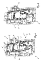
- a receiving device 1 can be designed as a front-end module, which can be fastened to a body of the motor vehicle via mounting brackets. Alternatively, the receiving device 1 may also be part of the body of the vehicle.
- the receiving device 1 has a receiving trough 2 for releasably securing a lighting unit 3. Like from the Figures 1 and 2 it can be seen, the receiving device 1 has an upper receiving trough 2 (body recess) for receiving a designed as a main headlamp light unit 3 and a lower receiving trough 2 'for receiving a designed as an additional headlamp light unit 3. In the following, only the attachment of the upper lighting unit 3 will be discussed.
- the fastening device has, on the one hand, a sliding / latching unit 4, which is arranged on a rear side 5 of the receiving device 1.
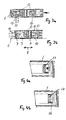
- the sliding / latching unit 4 has a rectilinear slide 6 which is mounted so as to be longitudinally displaceable in a slot formed by lugs 7 formed on the rear side 5 of the receiving device 1.
- the slider 6 is along a arranged perpendicular to a vehicle longitudinal axis extending sliding path 8 linearly movable.
- the slider 6 has at least one slot 9 and two spaced along the slider 6 to each other arranged clamping elements 10.
- the clamping elements 10 are designed as spring elements which have two spring arms 11, which are arranged transversely to the extension of the slider 6 resiliently. In accordance with FIG. 1 illustrated locking position of the slider 6 engage around the spring arms 11 latching a projecting from a rear side 12 of the light unit 3 pin 13, so that the light unit 3 is fixed in the receiving trough 2.
- a cross member 16 of the slider 6 is a fixed element 17 associated with the receiving device 1, so that the slider 6 can be fixed in the unlocked position. This ensures that during the insertion process of the lighting unit 3 into the receiving trough 2, the pin 13 can engage freely in the slot 9.
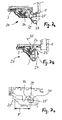
- a tilting unit 20 by means of which the lighting unit 3 after unlocking while moving along the translational guide track 14 about a pivot axis 21 along a rotary guide track 22 in an outer end position 23 is movable.
- the lighting unit 3 is held inclined at the edge 18 of the receiving opening 19, wherein the rear side 12 of the lighting unit 3 is accessible for making a change of light source.
- the tilting unit 20 forms a hinge unit, wherein a fork-shaped hinge element 24 of the lighting unit 3 engages around a cylindrical hinge element 25 of the receiving device 1 in the hinge position of the receiving device 1.
- the longitudinal axis of the hinge element 25 thus forms the pivot axis 21, which is skewed or perpendicular to the translational guide track 14 and perpendicular to the vehicle longitudinal axis.
- the hinge element 24 of the lighting unit 3 is arranged at a distance F to the hinge element 25 of the receiving device 1. This distance F corresponds to the length of the translatory guide track 14.
- the cylindrical hinge element 25 may also be formed on the extension 26 of the lighting unit 3 and the fork-shaped hinge element 24 on the receiving unit 1.
- the hinge element 24 of the lighting unit 3 extends at the end of an extension 26 of the lighting unit 3, which protrudes substantially below a housing of the lighting unit 3 at an angle from an underside.
- the hinge elements 25 of the receiving device 1 are arranged integrated in an attachable to the receiving device 1 insert member 27.
- the insert member 27 has a flat support threshold 28, so that the ends of the extension 6 are supported.
- the hinge element 25 of the receiving device 1 is shaped such that the lighting unit 3 can be pivoted about an acute or obtuse angle along the rotational trajectory 22, preferably 75 °. In an inclined outer end position of the lighting unit 3 abuts one end of a hinge arm 29 on a stop surface 30 of the hinge 25 at. In this outer end position 23, the lighting unit 3 is supported solely by the receiving device 1.
- the slider 6 is first moved from the locked position to an unlocked position.
- the lighting unit 3 can now be moved from the inner end position into an intermediate position 31, the lighting unit 3 being guided along a translatory guide track 14.
- the receiving device 1 on side walls elongated ribs 32 on which lugs 33 of the light unit 3 slide along.
- the lighting unit 3 By applying one in the axial direction the light unit 3 acting force the light unit 3 is now pivoted about the pivot axis 21 so far until it has reached the outer end position 23.
- the lighting means By opening a cap arranged on the back side of the lighting unit 3, the lighting means can now be exchanged.
- the hinge unit is designed so stable that the lighting unit 3 can be kept in the tilted state.
- this can be done by a light source change in a comfortable height of the light unit 3. It is ensured that the lighting unit 3 can not be removed automatically from the receiving device 1.
- the lighting unit 3 After changing the light source, the lighting unit 3 is pivoted back out of the outer end position 23 into the intermediate position 31 and subsequently moved along the translatory guide track 14 into the inner end position. By subsequently locking the slider 8, the lighting unit 3 is fixed again in the receiving trough 2.
- the receptacles may be formed as perforations or recesses, which allow a defined relative position of the lighting unit 3 to the receiving device 1.
- the lighting unit 3 For mounting the lighting unit 3, this can be applied by engaging the corresponding hinge elements 24 of the lighting unit 3 and the hinge elements 25 of the receiving device 1.
- the lighting unit 3 thus has a defined insertion position to the receiving device 1.
- the following can - as in the Lamp change - the lighting unit 3 are spent by pivoting along the rotary guideway 22 and subsequent displacement along the translational guide track in the inner end position, in which by locking means the locking of the light unit 3 takes place.
- two fastening tabs 40 are mounted on the back 5 of the receiving device 1 by means of screw 41.
- the elongate attachment tabs 40 extend substantially in the vertical direction or at a relatively small acute angle to a vertical plane.
- two fastening tabs 40 are provided, which are arranged at a distance from each other.
Landscapes
- Engineering & Computer Science (AREA)
- Mechanical Engineering (AREA)
- Lighting Device Outwards From Vehicle And Optical Signal (AREA)
Applications Claiming Priority (1)
| Application Number | Priority Date | Filing Date | Title |
|---|---|---|---|
| DE102007062434A DE102007062434A1 (de) | 2007-12-20 | 2007-12-20 | Befestigungsvorrichtung für eine Leuchteinheit und Verfahren zum Leuchtmittelwechsel |
Publications (3)
| Publication Number | Publication Date |
|---|---|
| EP2072331A2 true EP2072331A2 (fr) | 2009-06-24 |
| EP2072331A3 EP2072331A3 (fr) | 2009-09-30 |
| EP2072331B1 EP2072331B1 (fr) | 2015-02-11 |
Family
ID=40474686
Family Applications (1)
| Application Number | Title | Priority Date | Filing Date |
|---|---|---|---|
| EP08019451.7A Not-in-force EP2072331B1 (fr) | 2007-12-20 | 2008-11-06 | Dispositif de fixation pour une unité d'éclairage et procédé de changement de moyen d'éclairage |
Country Status (2)
| Country | Link |
|---|---|
| EP (1) | EP2072331B1 (fr) |
| DE (1) | DE102007062434A1 (fr) |
Cited By (2)
| Publication number | Priority date | Publication date | Assignee | Title |
|---|---|---|---|---|
| DE102010021567A1 (de) * | 2010-05-26 | 2011-12-01 | Gm Global Technology Operations Llc (N.D.Ges.D. Staates Delaware) | Scheinwerferanordnung für ein Kraftfahrzeug |
| US10400977B2 (en) | 2017-02-27 | 2019-09-03 | Motor Coach Industries Limited | Quick adjust vehicle headlight assembly |
Families Citing this family (3)
| Publication number | Priority date | Publication date | Assignee | Title |
|---|---|---|---|---|
| DE102011011701A1 (de) * | 2011-02-18 | 2012-08-23 | Gm Global Technology Operations, Llc | Montageträger für Frontscheinwerfer |
| DE102011115797A1 (de) * | 2011-10-11 | 2013-04-11 | Gm Global Technology Operations, Llc | Scheinwerferbaueinheit eines Fahrzeugs mit Scheinwerferbefestigungsvorrichtung |
| DE102022202836A1 (de) | 2022-03-23 | 2023-09-28 | Psa Automobiles Sa | Karosserieteil zum Aufnehmen einer Außenleuchtvorrichtung eines Fahrzeugs sowie die Außenleuchtvorrichtung und ein Verfahren zur Montage der Außenleuchtvorrichtung |
Citations (5)
| Publication number | Priority date | Publication date | Assignee | Title |
|---|---|---|---|---|
| US5428511A (en) | 1994-09-29 | 1995-06-27 | General Motors Corporation | Quick release vehicle headlamp arrangement |
| DE4133002C3 (de) | 1991-10-04 | 1996-02-15 | Bayerische Motoren Werke Ag | Befestigungsvorrichtung für eine Kraftfahrzeug-Scheinwerfer-Baueinheit |
| EP1103417A1 (fr) | 1999-11-29 | 2001-05-30 | Valeo Vision | Véhicule à dispositif d'éclairage et/ou de signalisation monté mobile |
| EP1231107A1 (fr) | 2001-02-08 | 2002-08-14 | Faurecia Industries | Bloc optique de véhicule comportant des moyens de fixation de projecteurs améliorés |
| DE19741522C2 (de) | 1997-09-20 | 2002-08-22 | Bosch Gmbh Robert | Vormontierbare Baueinheit |
Family Cites Families (14)
| Publication number | Priority date | Publication date | Assignee | Title |
|---|---|---|---|---|
| JPH0329232Y2 (fr) * | 1985-07-19 | 1991-06-21 | ||
| IT1232138B (it) * | 1989-07-07 | 1992-01-23 | Carello Spa | Proiettore incassato, particolarmente per autoveicoli |
| DE4127716C1 (en) * | 1991-08-22 | 1992-06-17 | Mercedes-Benz Aktiengesellschaft, 7000 Stuttgart, De | Motor vehicle headlamp mounted above bumper - has hinged lever allowing pivoting outwards from bodywork recess for changing bulb |
| JPH06107060A (ja) * | 1992-09-30 | 1994-04-19 | Mazda Motor Corp | ヘッドランプ取付構造 |
| DE4311419C2 (de) * | 1993-04-07 | 1995-09-07 | Porsche Ag | Befestigungsvorrichtung für einen Schweinwerfer |
| US5420762A (en) * | 1993-09-24 | 1995-05-30 | Trw Inc. | Automotive headlamp assembly fastening system |
| DE4334721B4 (de) * | 1993-10-12 | 2005-06-23 | Automotive Lighting Reutlingen Gmbh | Scheinwerfer für Fahrzeuge |
| DE19741605B4 (de) * | 1996-09-27 | 2006-06-29 | Volkswagen Ag | Befestigungsvorrichtung für einen Scheinwerfer an einem Kraftfahrzeug |
| JP3443598B2 (ja) * | 1997-10-22 | 2003-09-02 | 日野自動車株式会社 | 車両用フロント灯火装置の取付構造 |
| FR2785037B1 (fr) * | 1998-10-21 | 2001-03-23 | Valeo Vision | Dispositif d'eclairage ou de signalisation pour vehicule automobile, en particulier projecteur, equipe de nouveaux moyens d'acces a une lampe |
| JP3891007B2 (ja) * | 2001-04-23 | 2007-03-07 | 日産自動車株式会社 | 自動車の車体前部構造及び車体前部の組付方法 |
| FR2833661B1 (fr) * | 2001-12-19 | 2004-08-13 | Renault | Dispositif de fixation d'accessoire notamment automobile, en particulier feu de signalisation |
| JP2004314873A (ja) * | 2003-04-18 | 2004-11-11 | Toyota Motor Corp | 車両用ランプ取付構造 |
| DE102006017166A1 (de) * | 2006-04-12 | 2007-10-18 | Hella Kgaa Hueck & Co. | Verfahren zur Montage eines Scheinwerfers und Befestigungsvorrichtung |
-
2007
- 2007-12-20 DE DE102007062434A patent/DE102007062434A1/de not_active Withdrawn
-
2008
- 2008-11-06 EP EP08019451.7A patent/EP2072331B1/fr not_active Not-in-force
Patent Citations (5)
| Publication number | Priority date | Publication date | Assignee | Title |
|---|---|---|---|---|
| DE4133002C3 (de) | 1991-10-04 | 1996-02-15 | Bayerische Motoren Werke Ag | Befestigungsvorrichtung für eine Kraftfahrzeug-Scheinwerfer-Baueinheit |
| US5428511A (en) | 1994-09-29 | 1995-06-27 | General Motors Corporation | Quick release vehicle headlamp arrangement |
| DE19741522C2 (de) | 1997-09-20 | 2002-08-22 | Bosch Gmbh Robert | Vormontierbare Baueinheit |
| EP1103417A1 (fr) | 1999-11-29 | 2001-05-30 | Valeo Vision | Véhicule à dispositif d'éclairage et/ou de signalisation monté mobile |
| EP1231107A1 (fr) | 2001-02-08 | 2002-08-14 | Faurecia Industries | Bloc optique de véhicule comportant des moyens de fixation de projecteurs améliorés |
Cited By (2)
| Publication number | Priority date | Publication date | Assignee | Title |
|---|---|---|---|---|
| DE102010021567A1 (de) * | 2010-05-26 | 2011-12-01 | Gm Global Technology Operations Llc (N.D.Ges.D. Staates Delaware) | Scheinwerferanordnung für ein Kraftfahrzeug |
| US10400977B2 (en) | 2017-02-27 | 2019-09-03 | Motor Coach Industries Limited | Quick adjust vehicle headlight assembly |
Also Published As
| Publication number | Publication date |
|---|---|
| DE102007062434A1 (de) | 2009-06-25 |
| EP2072331B1 (fr) | 2015-02-11 |
| EP2072331A3 (fr) | 2009-09-30 |
Similar Documents
| Publication | Publication Date | Title |
|---|---|---|
| EP2152542B1 (fr) | Module d'extrémité avant pour véhicules | |
| DE4311419C2 (de) | Befestigungsvorrichtung für einen Schweinwerfer | |
| DE2847908C3 (de) | Blinkleuchte-Scheinwerfer-Befestigung in Kraftfahrzeugkarosserien | |
| EP2072331B1 (fr) | Dispositif de fixation pour une unité d'éclairage et procédé de changement de moyen d'éclairage | |
| DE102009011708B4 (de) | Fahrzeugleuchte | |
| EP2762390A1 (fr) | Dispositif de fixation et procédé d'orientation pour des accessoires de véhicules | |
| EP1780086B1 (fr) | Dispositif pour fixer en position exacte un pare-chocs | |
| DE102012109940A1 (de) | Vorrichtung zur Einstellung einer Fuge zwischen Anbauteilen | |
| EP1912827B1 (fr) | Dispositif de fixation reglable d'un phare | |
| DE2353322A1 (de) | Scheinwerfer fuer kraftfahrzeuge | |
| EP1871644B1 (fr) | Phare de vehicule comprenant un composant amovible une fois monte | |
| DE19745928C2 (de) | Türfeststeller an einer Kraftfahrzeugtür | |
| DE102012200004B4 (de) | Verstellvorrichtung für Scheinwerfer | |
| DE102006027460A1 (de) | Vorrichtung und Verfahren zum Befestigen und Ausrichten einer Leuchteinheit | |
| DE102007062435B4 (de) | Befestigungsvorrichtung für eine Leuchteinheit | |
| DE102006018305B4 (de) | Scheinwerfer für Fahrzeuge | |
| DE9312695U1 (de) | Einstellanordnung für die Verschwenkbarkeit eines Reflektors eines Kraftfahrzeugscheinwerfers | |
| EP1384622A1 (fr) | Ensemble d'eclairage et procede de fixation d'un ensemble d'eclairage | |
| EP1710122B1 (fr) | Projecteur pour véhicules | |
| EP4382708A2 (fr) | Dispositif de guidage pour guider au moins une partie de meuble mobile | |
| DE102008011716A1 (de) | Scheinwerferanordnung mit einem verbesserten Einstellsystem | |
| DE69005673T2 (de) | Scheinwerfer mit einstellbarem Lichtstrahlwinkel. | |
| DE102007026262A1 (de) | Leuchteinheit für Fahrzeuge | |
| DE102007024558A1 (de) | Scheinwerfer für Fahrzeuge | |
| DE102011000557B4 (de) | Verstellvorrichtung für Scheinwerfer |
Legal Events
| Date | Code | Title | Description |
|---|---|---|---|
| PUAI | Public reference made under article 153(3) epc to a published international application that has entered the european phase |
Free format text: ORIGINAL CODE: 0009012 |
|
| AK | Designated contracting states |
Kind code of ref document: A2 Designated state(s): AT BE BG CH CY CZ DE DK EE ES FI FR GB GR HR HU IE IS IT LI LT LU LV MC MT NL NO PL PT RO SE SI SK TR |
|
| AX | Request for extension of the european patent |
Extension state: AL BA MK RS |
|
| PUAL | Search report despatched |
Free format text: ORIGINAL CODE: 0009013 |
|
| AK | Designated contracting states |
Kind code of ref document: A3 Designated state(s): AT BE BG CH CY CZ DE DK EE ES FI FR GB GR HR HU IE IS IT LI LT LU LV MC MT NL NO PL PT RO SE SI SK TR |
|
| AX | Request for extension of the european patent |
Extension state: AL BA MK RS |
|
| 17P | Request for examination filed |
Effective date: 20100315 |
|
| 17Q | First examination report despatched |
Effective date: 20100412 |
|
| AKX | Designation fees paid |
Designated state(s): AT BE BG CH CY CZ DE DK EE ES FI FR GB GR HR HU IE IS IT LI LT LU LV MC MT NL NO PL PT RO SE SI SK TR |
|
| GRAP | Despatch of communication of intention to grant a patent |
Free format text: ORIGINAL CODE: EPIDOSNIGR1 |
|
| INTG | Intention to grant announced |
Effective date: 20140915 |
|
| GRAS | Grant fee paid |
Free format text: ORIGINAL CODE: EPIDOSNIGR3 |
|
| GRAA | (expected) grant |
Free format text: ORIGINAL CODE: 0009210 |
|
| AK | Designated contracting states |
Kind code of ref document: B1 Designated state(s): AT BE BG CH CY CZ DE DK EE ES FI FR GB GR HR HU IE IS IT LI LT LU LV MC MT NL NO PL PT RO SE SI SK TR |
|
| REG | Reference to a national code |
Ref country code: GB Ref legal event code: FG4D Free format text: NOT ENGLISH |
|
| REG | Reference to a national code |
Ref country code: CH Ref legal event code: EP |
|
| REG | Reference to a national code |
Ref country code: IE Ref legal event code: FG4D Free format text: LANGUAGE OF EP DOCUMENT: GERMAN |
|
| REG | Reference to a national code |
Ref country code: AT Ref legal event code: REF Ref document number: 709808 Country of ref document: AT Kind code of ref document: T Effective date: 20150315 |
|
| REG | Reference to a national code |
Ref country code: DE Ref legal event code: R096 Ref document number: 502008012658 Country of ref document: DE Effective date: 20150326 |
|
| REG | Reference to a national code |
Ref country code: DE Ref legal event code: R081 Ref document number: 502008012658 Country of ref document: DE Owner name: HELLA KGAA HUECK & CO., DE Free format text: FORMER OWNER: HELLA AUTOTECHNIK SPOL. S.R.O., HELLA KGAA HUECK & CO., , CZ Ref country code: DE Ref legal event code: R081 Ref document number: 502008012658 Country of ref document: DE Owner name: HELLA AUTOTECHNIK NOVA, S.R.O., CZ Free format text: FORMER OWNER: HELLA AUTOTECHNIK SPOL. S.R.O., HELLA KGAA HUECK & CO., , CZ Ref country code: DE Ref legal event code: R081 Ref document number: 502008012658 Country of ref document: DE Owner name: HELLA AUTOTECHNIK NOVA, S.R.O., CZ Free format text: FORMER OWNERS: HELLA AUTOTECHNIK SPOL. S.R.O., MOHELNICE, CZ; HELLA KGAA HUECK & CO., 59557 LIPPSTADT, DE Ref country code: DE Ref legal event code: R081 Ref document number: 502008012658 Country of ref document: DE Owner name: HELLA KGAA HUECK & CO., DE Free format text: FORMER OWNERS: HELLA AUTOTECHNIK SPOL. S.R.O., MOHELNICE, CZ; HELLA KGAA HUECK & CO., 59557 LIPPSTADT, DE Ref country code: DE Ref legal event code: R081 Ref document number: 502008012658 Country of ref document: DE Owner name: HELLA GMBH & CO. KGAA, DE Free format text: FORMER OWNERS: HELLA AUTOTECHNIK SPOL. S.R.O., MOHELNICE, CZ; HELLA KGAA HUECK & CO., 59557 LIPPSTADT, DE |
|
| REG | Reference to a national code |
Ref country code: NL Ref legal event code: VDEP Effective date: 20150211 |
|
| RAP2 | Party data changed (patent owner data changed or rights of a patent transferred) |
Owner name: HELLA AUTOTECHNIK NOVA, S.R.O. Owner name: HELLA KGAA HUECK & CO. |
|
| REG | Reference to a national code |
Ref country code: LT Ref legal event code: MG4D |
|
| PG25 | Lapsed in a contracting state [announced via postgrant information from national office to epo] |
Ref country code: HR Free format text: LAPSE BECAUSE OF FAILURE TO SUBMIT A TRANSLATION OF THE DESCRIPTION OR TO PAY THE FEE WITHIN THE PRESCRIBED TIME-LIMIT Effective date: 20150211 Ref country code: SE Free format text: LAPSE BECAUSE OF FAILURE TO SUBMIT A TRANSLATION OF THE DESCRIPTION OR TO PAY THE FEE WITHIN THE PRESCRIBED TIME-LIMIT Effective date: 20150211 Ref country code: NO Free format text: LAPSE BECAUSE OF FAILURE TO SUBMIT A TRANSLATION OF THE DESCRIPTION OR TO PAY THE FEE WITHIN THE PRESCRIBED TIME-LIMIT Effective date: 20150511 Ref country code: ES Free format text: LAPSE BECAUSE OF FAILURE TO SUBMIT A TRANSLATION OF THE DESCRIPTION OR TO PAY THE FEE WITHIN THE PRESCRIBED TIME-LIMIT Effective date: 20150211 Ref country code: LT Free format text: LAPSE BECAUSE OF FAILURE TO SUBMIT A TRANSLATION OF THE DESCRIPTION OR TO PAY THE FEE WITHIN THE PRESCRIBED TIME-LIMIT Effective date: 20150211 Ref country code: FI Free format text: LAPSE BECAUSE OF FAILURE TO SUBMIT A TRANSLATION OF THE DESCRIPTION OR TO PAY THE FEE WITHIN THE PRESCRIBED TIME-LIMIT Effective date: 20150211 |
|
| PG25 | Lapsed in a contracting state [announced via postgrant information from national office to epo] |
Ref country code: IS Free format text: LAPSE BECAUSE OF FAILURE TO SUBMIT A TRANSLATION OF THE DESCRIPTION OR TO PAY THE FEE WITHIN THE PRESCRIBED TIME-LIMIT Effective date: 20150611 Ref country code: NL Free format text: LAPSE BECAUSE OF FAILURE TO SUBMIT A TRANSLATION OF THE DESCRIPTION OR TO PAY THE FEE WITHIN THE PRESCRIBED TIME-LIMIT Effective date: 20150211 Ref country code: GR Free format text: LAPSE BECAUSE OF FAILURE TO SUBMIT A TRANSLATION OF THE DESCRIPTION OR TO PAY THE FEE WITHIN THE PRESCRIBED TIME-LIMIT Effective date: 20150512 Ref country code: LV Free format text: LAPSE BECAUSE OF FAILURE TO SUBMIT A TRANSLATION OF THE DESCRIPTION OR TO PAY THE FEE WITHIN THE PRESCRIBED TIME-LIMIT Effective date: 20150211 |
|
| PG25 | Lapsed in a contracting state [announced via postgrant information from national office to epo] |
Ref country code: DK Free format text: LAPSE BECAUSE OF FAILURE TO SUBMIT A TRANSLATION OF THE DESCRIPTION OR TO PAY THE FEE WITHIN THE PRESCRIBED TIME-LIMIT Effective date: 20150211 Ref country code: EE Free format text: LAPSE BECAUSE OF FAILURE TO SUBMIT A TRANSLATION OF THE DESCRIPTION OR TO PAY THE FEE WITHIN THE PRESCRIBED TIME-LIMIT Effective date: 20150211 Ref country code: RO Free format text: LAPSE BECAUSE OF FAILURE TO SUBMIT A TRANSLATION OF THE DESCRIPTION OR TO PAY THE FEE WITHIN THE PRESCRIBED TIME-LIMIT Effective date: 20150211 Ref country code: SK Free format text: LAPSE BECAUSE OF FAILURE TO SUBMIT A TRANSLATION OF THE DESCRIPTION OR TO PAY THE FEE WITHIN THE PRESCRIBED TIME-LIMIT Effective date: 20150211 |
|
| REG | Reference to a national code |
Ref country code: DE Ref legal event code: R097 Ref document number: 502008012658 Country of ref document: DE |
|
| REG | Reference to a national code |
Ref country code: FR Ref legal event code: PLFP Year of fee payment: 8 |
|
| PG25 | Lapsed in a contracting state [announced via postgrant information from national office to epo] |
Ref country code: PL Free format text: LAPSE BECAUSE OF FAILURE TO SUBMIT A TRANSLATION OF THE DESCRIPTION OR TO PAY THE FEE WITHIN THE PRESCRIBED TIME-LIMIT Effective date: 20150211 |
|
| PLBE | No opposition filed within time limit |
Free format text: ORIGINAL CODE: 0009261 |
|
| STAA | Information on the status of an ep patent application or granted ep patent |
Free format text: STATUS: NO OPPOSITION FILED WITHIN TIME LIMIT |
|
| PG25 | Lapsed in a contracting state [announced via postgrant information from national office to epo] |
Ref country code: IT Free format text: LAPSE BECAUSE OF FAILURE TO SUBMIT A TRANSLATION OF THE DESCRIPTION OR TO PAY THE FEE WITHIN THE PRESCRIBED TIME-LIMIT Effective date: 20150211 |
|
| 26N | No opposition filed |
Effective date: 20151112 |
|
| PGFP | Annual fee paid to national office [announced via postgrant information from national office to epo] |
Ref country code: GB Payment date: 20151123 Year of fee payment: 8 |
|
| PG25 | Lapsed in a contracting state [announced via postgrant information from national office to epo] |
Ref country code: SI Free format text: LAPSE BECAUSE OF FAILURE TO SUBMIT A TRANSLATION OF THE DESCRIPTION OR TO PAY THE FEE WITHIN THE PRESCRIBED TIME-LIMIT Effective date: 20150211 |
|
| PG25 | Lapsed in a contracting state [announced via postgrant information from national office to epo] |
Ref country code: LU Free format text: LAPSE BECAUSE OF FAILURE TO SUBMIT A TRANSLATION OF THE DESCRIPTION OR TO PAY THE FEE WITHIN THE PRESCRIBED TIME-LIMIT Effective date: 20151106 Ref country code: MC Free format text: LAPSE BECAUSE OF FAILURE TO SUBMIT A TRANSLATION OF THE DESCRIPTION OR TO PAY THE FEE WITHIN THE PRESCRIBED TIME-LIMIT Effective date: 20150211 |
|
| REG | Reference to a national code |
Ref country code: CH Ref legal event code: PL |
|
| PG25 | Lapsed in a contracting state [announced via postgrant information from national office to epo] |
Ref country code: LI Free format text: LAPSE BECAUSE OF NON-PAYMENT OF DUE FEES Effective date: 20151130 Ref country code: CH Free format text: LAPSE BECAUSE OF NON-PAYMENT OF DUE FEES Effective date: 20151130 |
|
| REG | Reference to a national code |
Ref country code: IE Ref legal event code: MM4A |
|
| PG25 | Lapsed in a contracting state [announced via postgrant information from national office to epo] |
Ref country code: IE Free format text: LAPSE BECAUSE OF NON-PAYMENT OF DUE FEES Effective date: 20151106 |
|
| REG | Reference to a national code |
Ref country code: FR Ref legal event code: PLFP Year of fee payment: 9 |
|
| REG | Reference to a national code |
Ref country code: AT Ref legal event code: PC Ref document number: 709808 Country of ref document: AT Kind code of ref document: T Owner name: HELLA AUTOTECHNIK NOVA. S.R.O., CZ Effective date: 20161018 Ref country code: AT Ref legal event code: PC Ref document number: 709808 Country of ref document: AT Kind code of ref document: T Owner name: HELLA KGAA HUECK & CO., DE Effective date: 20161018 |
|
| PGFP | Annual fee paid to national office [announced via postgrant information from national office to epo] |
Ref country code: CZ Payment date: 20161026 Year of fee payment: 9 Ref country code: FR Payment date: 20161124 Year of fee payment: 9 Ref country code: DE Payment date: 20161110 Year of fee payment: 9 |
|
| PGFP | Annual fee paid to national office [announced via postgrant information from national office to epo] |
Ref country code: AT Payment date: 20161122 Year of fee payment: 9 |
|
| PG25 | Lapsed in a contracting state [announced via postgrant information from national office to epo] |
Ref country code: HU Free format text: LAPSE BECAUSE OF FAILURE TO SUBMIT A TRANSLATION OF THE DESCRIPTION OR TO PAY THE FEE WITHIN THE PRESCRIBED TIME-LIMIT; INVALID AB INITIO Effective date: 20081106 Ref country code: BG Free format text: LAPSE BECAUSE OF FAILURE TO SUBMIT A TRANSLATION OF THE DESCRIPTION OR TO PAY THE FEE WITHIN THE PRESCRIBED TIME-LIMIT Effective date: 20150211 |
|
| PG25 | Lapsed in a contracting state [announced via postgrant information from national office to epo] |
Ref country code: CY Free format text: LAPSE BECAUSE OF FAILURE TO SUBMIT A TRANSLATION OF THE DESCRIPTION OR TO PAY THE FEE WITHIN THE PRESCRIBED TIME-LIMIT Effective date: 20150211 |
|
| GBPC | Gb: european patent ceased through non-payment of renewal fee |
Effective date: 20161106 |
|
| PG25 | Lapsed in a contracting state [announced via postgrant information from national office to epo] |
Ref country code: BE Free format text: LAPSE BECAUSE OF NON-PAYMENT OF DUE FEES Effective date: 20151130 |
|
| PG25 | Lapsed in a contracting state [announced via postgrant information from national office to epo] |
Ref country code: MT Free format text: LAPSE BECAUSE OF FAILURE TO SUBMIT A TRANSLATION OF THE DESCRIPTION OR TO PAY THE FEE WITHIN THE PRESCRIBED TIME-LIMIT Effective date: 20150211 Ref country code: TR Free format text: LAPSE BECAUSE OF FAILURE TO SUBMIT A TRANSLATION OF THE DESCRIPTION OR TO PAY THE FEE WITHIN THE PRESCRIBED TIME-LIMIT Effective date: 20150211 |
|
| PG25 | Lapsed in a contracting state [announced via postgrant information from national office to epo] |
Ref country code: GB Free format text: LAPSE BECAUSE OF NON-PAYMENT OF DUE FEES Effective date: 20161106 |
|
| REG | Reference to a national code |
Ref country code: DE Ref legal event code: R082 Ref document number: 502008012658 Country of ref document: DE Representative=s name: PATENTANWAELTE FIEDLER, OSTERMANN & SCHNEIDER, DE Ref country code: DE Ref legal event code: R081 Ref document number: 502008012658 Country of ref document: DE Owner name: HELLA GMBH & CO. KGAA, DE Free format text: FORMER OWNERS: HELLA AUTOTECHNIK NOVA, S.R.O., MOHELNICE, CZ; HELLA KGAA HUECK & CO., 59557 LIPPSTADT, DE Ref country code: DE Ref legal event code: R081 Ref document number: 502008012658 Country of ref document: DE Owner name: HELLA AUTOTECHNIK NOVA, S.R.O., CZ Free format text: FORMER OWNERS: HELLA AUTOTECHNIK NOVA, S.R.O., MOHELNICE, CZ; HELLA KGAA HUECK & CO., 59557 LIPPSTADT, DE |
|
| REG | Reference to a national code |
Ref country code: DE Ref legal event code: R119 Ref document number: 502008012658 Country of ref document: DE |
|
| PG25 | Lapsed in a contracting state [announced via postgrant information from national office to epo] |
Ref country code: PT Free format text: LAPSE BECAUSE OF FAILURE TO SUBMIT A TRANSLATION OF THE DESCRIPTION OR TO PAY THE FEE WITHIN THE PRESCRIBED TIME-LIMIT Effective date: 20150211 |
|
| REG | Reference to a national code |
Ref country code: AT Ref legal event code: MM01 Ref document number: 709808 Country of ref document: AT Kind code of ref document: T Effective date: 20171106 |
|
| PG25 | Lapsed in a contracting state [announced via postgrant information from national office to epo] |
Ref country code: CZ Free format text: LAPSE BECAUSE OF NON-PAYMENT OF DUE FEES Effective date: 20171106 |
|
| PG25 | Lapsed in a contracting state [announced via postgrant information from national office to epo] |
Ref country code: AT Free format text: LAPSE BECAUSE OF NON-PAYMENT OF DUE FEES Effective date: 20171106 |
|
| REG | Reference to a national code |
Ref country code: FR Ref legal event code: ST Effective date: 20180731 |
|
| PG25 | Lapsed in a contracting state [announced via postgrant information from national office to epo] |
Ref country code: FR Free format text: LAPSE BECAUSE OF NON-PAYMENT OF DUE FEES Effective date: 20171130 Ref country code: DE Free format text: LAPSE BECAUSE OF NON-PAYMENT OF DUE FEES Effective date: 20180602 |