EP2072361A1 - Vorrichtung zur hydraulischen Steuerung eines Hauptbremszylinders - Google Patents
Vorrichtung zur hydraulischen Steuerung eines Hauptbremszylinders Download PDFInfo
- Publication number
- EP2072361A1 EP2072361A1 EP08171916A EP08171916A EP2072361A1 EP 2072361 A1 EP2072361 A1 EP 2072361A1 EP 08171916 A EP08171916 A EP 08171916A EP 08171916 A EP08171916 A EP 08171916A EP 2072361 A1 EP2072361 A1 EP 2072361A1
- Authority
- EP
- European Patent Office
- Prior art keywords
- brake
- chamber
- control
- piston
- master cylinder
- Prior art date
- Legal status (The legal status is an assumption and is not a legal conclusion. Google has not performed a legal analysis and makes no representation as to the accuracy of the status listed.)
- Granted
Links
- 239000012530 fluid Substances 0.000 claims description 38
- 238000006073 displacement reaction Methods 0.000 claims description 15
- 238000002955 isolation Methods 0.000 claims description 3
- 238000004088 simulation Methods 0.000 description 11
- 230000005540 biological transmission Effects 0.000 description 3
- LRUUNMYPIBZBQH-UHFFFAOYSA-N Methazole Chemical compound O=C1N(C)C(=O)ON1C1=CC=C(Cl)C(Cl)=C1 LRUUNMYPIBZBQH-UHFFFAOYSA-N 0.000 description 2
- 238000001514 detection method Methods 0.000 description 2
- 230000000903 blocking effect Effects 0.000 description 1
- 229940082150 encore Drugs 0.000 description 1
- 239000000523 sample Substances 0.000 description 1
Images


Classifications
-
- B—PERFORMING OPERATIONS; TRANSPORTING
- B60—VEHICLES IN GENERAL
- B60T—VEHICLE BRAKE CONTROL SYSTEMS OR PARTS THEREOF; BRAKE CONTROL SYSTEMS OR PARTS THEREOF, IN GENERAL; ARRANGEMENT OF BRAKING ELEMENTS ON VEHICLES IN GENERAL; PORTABLE DEVICES FOR PREVENTING UNWANTED MOVEMENT OF VEHICLES; VEHICLE MODIFICATIONS TO FACILITATE COOLING OF BRAKES
- B60T13/00—Transmitting braking action from initiating means to ultimate brake actuator with power assistance or drive; Brake systems incorporating such transmitting means, e.g. air-pressure brake systems
- B60T13/10—Transmitting braking action from initiating means to ultimate brake actuator with power assistance or drive; Brake systems incorporating such transmitting means, e.g. air-pressure brake systems with fluid assistance, drive, or release
- B60T13/24—Transmitting braking action from initiating means to ultimate brake actuator with power assistance or drive; Brake systems incorporating such transmitting means, e.g. air-pressure brake systems with fluid assistance, drive, or release the fluid being gaseous
- B60T13/46—Vacuum systems
- B60T13/52—Vacuum systems indirect, i.e. vacuum booster units
-
- B—PERFORMING OPERATIONS; TRANSPORTING
- B60—VEHICLES IN GENERAL
- B60T—VEHICLE BRAKE CONTROL SYSTEMS OR PARTS THEREOF; BRAKE CONTROL SYSTEMS OR PARTS THEREOF, IN GENERAL; ARRANGEMENT OF BRAKING ELEMENTS ON VEHICLES IN GENERAL; PORTABLE DEVICES FOR PREVENTING UNWANTED MOVEMENT OF VEHICLES; VEHICLE MODIFICATIONS TO FACILITATE COOLING OF BRAKES
- B60T13/00—Transmitting braking action from initiating means to ultimate brake actuator with power assistance or drive; Brake systems incorporating such transmitting means, e.g. air-pressure brake systems
- B60T13/10—Transmitting braking action from initiating means to ultimate brake actuator with power assistance or drive; Brake systems incorporating such transmitting means, e.g. air-pressure brake systems with fluid assistance, drive, or release
- B60T13/24—Transmitting braking action from initiating means to ultimate brake actuator with power assistance or drive; Brake systems incorporating such transmitting means, e.g. air-pressure brake systems with fluid assistance, drive, or release the fluid being gaseous
- B60T13/241—Differential pressure systems
- B60T13/242—The control valve is provided as one unit with the servomotor cylinder
- B60T13/245—Hydraulic command of the control valve, hydraulic transmission to the brake
Definitions
- the invention relates to a brake control system and more particularly to a system for controlling a hydraulic braking system for a motor vehicle.
- Hydraulic brake systems commonly used in motor vehicles currently include a brake master cylinder which is controlled by a pneumatic brake booster, which is actuated by the driver with the brake pedal.
- the brake assist servomotor is usually located in the front compartment of the vehicle, which is usually the engine compartment.
- the servomotor comprises a housing which is sealed with a cover. Inside this housing are two chambers separated by a piston. One room is empty, the other room is empty or atmospheric pressure. The difference in pressure between the two chambers provides the assistance and makes it possible to actuate the piston as is known in the art, and to retransmit forces transmitted by a control rod to a push rod which communicates the forces to the master cylinder. brakes
- Part of the servomotor passes through the deck including the control rod so that it can be controlled by the brake pedal when it is actuated by the driver.
- a wall of the actuator housing is fixed by means of screw and nut devices.
- the position of the braking assistance servomotor and the brake master cylinder is therefore determined by the position of the pedal.
- the braking assistance servomotor and the master cylinder constitute a relatively bulky assembly and its location near the brake pedal is a constraint for the designer of the motor vehicle.
- the attachment of the master cylinder on the brake booster drives the design of a relatively robust servomotor.
- WO 2007 042413 discloses a braking system comprising a control simulator of a pneumatic servomotor driving a hydraulic piston of a first assist master cylinder generating a boost pressure supplied to a thrust chamber of a second master cylinder.
- the invention provides a solution for freeing oneself from these constraints.
- the invention thus relates to a brake control system of a vehicle comprising a brake master cylinder and a brake assist actuator actuated by a control member such as a brake pedal.
- the servomotor is hydraulically coupled to the brake master cylinder and is not mechanically coupled to the primary piston of the master cylinder.
- the system of the invention comprises an auxiliary pressure device which is controlled by the control member and which makes it possible to control the brake booster.
- the invention relates to a brake control system characterized in that a source of pressurized hydraulic fluid is connected on command of the auxiliary pressure device to a thrust chamber of the master cylinder.
- the invention also relates to a brake control system characterized in that the isolation valve closed at rest, the auxiliary pressure source is controlled by the control member and the servomotor assistance.
- the auxiliary pressure device comprises a chamber filled with a fluid and a piston which slides in this chamber under the control of the control member. This enclosure is then connected by a first pipe to a control valve of the brake booster.
- the master brake cylinder has a control chamber for controlling the primary piston of the master brake cylinder, this control chamber being located on the opposite side to the primary chamber relative to the primary piston and it provides that the servomotor comprises a high pressure output connected to this control chamber by a second pipe to induce a pressure in the control chamber and control the primary piston.
- the brake booster is a hydraulic servomotor and advantageously comprises a hydraulic pump for supplying a high pressure fluid to the braking assistance servomotor.
- Said control valve makes it possible to transmit this fluid under high pressure to said control chamber by means of the second pipe.
- the braking assistance booster comprises an inlet chamber in which a control piston slides which makes it possible to control a first valve which is movable in an outlet chamber.
- This outlet chamber is connected to said second pipe.
- the first valve controls a second valve, which allows the hydraulic pump to communicate with the outlet chamber.
- control piston has a central piston acting on the first valve and sliding in an annular piston. It slides in the entrance and rests against a spring whose role is to oppose a resistance to displacement of the annular piston to simulate a braking force to the control member.
- the first valve makes it possible to connect the outlet chamber to the brake fluid reservoir to allow pressure to be released in the outlet chamber and therefore in the control chamber of the master cylinder.
- the master cylinder advantageously comprises a backup control piston which can slide in the control chamber under the action of a fluid transmitted by the auxiliary pressure device by a third pipe.
- the auxiliary pressure device is located in the brake master cylinder along the axis thereof and is contiguous to said control chamber.
- control chamber is preferably separated from the enclosure of the auxiliary pressure device by an axially movable piston.
- the master cylinder and the brake booster are in one piece.
- the invention also relates to an embodiment in which the servomotor brake assist is a pneumatic actuator.
- the system of the invention provides a pressure chamber controlled by the pneumatic servomotor and intended to supply a fluid under high pressure to said control chamber of the master cylinder via the second pipe.
- Said pressure chamber comprises a piston movable in the pressure booster chamber and is controlled by the displacement of said skirt.
- the braking assistance booster comprises a mobile simulation piston in the actuating chamber.
- This simulation piston moves under the action of the pressure in the actuating chamber and acts on the three-way valve via a simulation spring.
- the braking assistance booster comprises a simulation piston which is movable in the auxiliary pressure device. This simulation piston then moves under the action of the pressure in the auxiliary pressure device and acting on a simulation spring.
- the invention advantageously provides that the three-way valve is fixed in a wall of the casing of the pneumatic brake booster.
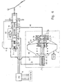
- the auxiliary pressure device 2 comprises a cavity 20 in which slides a piston 21 which is controlled by the brake pedal 1.
- the cavity 20 is filled with a fluid which makes it possible to transmit a hydraulic control to the braking assistance servomotor.
- the auxiliary pressure device 2 is associated with the brake pedal.
- the brake master cylinder not necessarily attached to the brake booster, but also the brake master cylinder and braking assist servomotor can be placed separately anywhere in the brake booster. vehicle.
- the servomotor 3 comprises an inlet chamber 30 which is connected by the pipe 46 to the auxiliary pressure device 2.
- An annular piston 31 is axially movable in the inlet chamber 30 and a central piston 32 is axially movable in the piston 31.
- a valve 33 is intended to rest on an axially movable valve seat 36.
- the mobile valve 36 is intended to control the axial displacement of the pusher 38 which is intended to push on the valve 40.
- a pressurized fluid pump 43 is connected via line 44 to an access cavity 42 of the pressurized fluid.
- the valve 40 makes it possible to put in communication an exit chamber 39, to which is connected to the pipe 45, with the access cavity 42.
- the valve 40 thus makes it possible to connect the control chamber 54 to the pressurized fluid pump via the pipe 45, the outlet chamber 39, the valve 40, the cavity 42 and the line 44.
- valve 40 At rest, the valve 40 is closed and isolates the pressurized fluid pump outlet chamber 39.
- the valve 33 is not applied against the valve seat 36.
- the control chamber 54 is in communication with the brake fluid reservoir via the pipe 45, the valve 33 and the pipe 47.
- the fluid of the control chamber 54 is therefore at atmospheric pressure.
- the primary and secondary chambers 51 and 53 are therefore also at this atmospheric pressure and do not provide a braking command to the circuits 8.
- the fluid contained in the control chamber 54 is pressurized and exerts pressure on the primary piston 50 of the master cylinder 5.
- the primary piston 50 and the secondary piston 52 move to the left and pressurize the primary and secondary chambers of the master cylinder. Braking pressure is transmitted to the braking circuits 9.
- the pressure in the outlet chamber 39 exerts a force towards the right on the pusher 38.
- the pusher allows the valve 40 to be closed.
- the fluid pump under pressure is isolated from the outlet chamber 39.
- the pressure in the control chamber 54 is maintained. In this state of equilibrium the valves 33 and 40 are closed.
- the invention also optionally provides for connecting the auxiliary pressure device 2 to the master cylinder via a pipe 49.
- a valve 61 is also provided.
- the figure 3 represents an alternative embodiment of the system of the figure 2 in which the auxiliary pressure device 2 is integrated in the master cylinder 5.
- the cavity 20 of the device 2 is placed along the axis of the master cylinder on the opposite side to the control chamber 54 with respect to the failure piston 55.
- the piston 21 induces a pressure in the inlet chamber 30, which controls the connection of the control chamber 54 to the source of pressurized fluid.
- the figure 4 represents in section, an exemplary embodiment in which, the master cylinder 5, the auxiliary pressure device 2 and the booster brake assist 3 are made in one piece.
- the wall which separates the servomotor portion 3 of the master cylinder 5 and the auxiliary chamber 2 comprises two internal pipes 45 and 46.
- the pipe 46 connects the auxiliary pressure device to the inlet chamber 30 of the booster and the pipe 45 connects the outlet chamber 39 to the control chamber 54 of the master cylinder.
- the figure 5 represents an embodiment of the system of the invention in which the braking assistance servomotor operates pneumatically on the basis of a pressure difference.
- This servomotor comprises a housing 8 whose interior is hermetically divided into two chambers 80 and 81 by a movable skirt 82.
- the chamber 80 that we will call low pressure chamber is connected to a vacuum pump Vac which tends to evacuate the chamber 80.
- the chamber 81 that we will call variable pressure chamber has its pressure determined by the three-way valve 7 as will be described below.
- the servomotor further comprises an inlet chamber 70 in which a piston 71 slides which makes it possible to act on the displacement of a plunger-distributor 79.
- the three-way valve is advantageously fixed in the right wall of the actuator housing. It comprises an annular valve seat 77 which is preferably fixed.
- a movable valve 76 is intended, depending on whether or not it is applied to the valve seat 77, to control the opening or closing of a first passage of the three-way valve and thus to isolate the low-pressure chambers. 80 and variable pressure 81 from each other.
- a movable probe 75 is integral with the plunger distributor 79 and makes it possible to control the opening or closing of a second passage between the variable pressure chamber 81 and a source of pressure (the atmospheric pressure for example) by moving away or approaching said movable flap 76.
- the chamber 20 of the auxiliary pressure device 2 is connected by a pipe 46 to the inlet chamber 70.
- the auxiliary pressure device 2 When the braking system is at rest, the auxiliary pressure device 2 does not induce pressure in the inlet chamber 70.
- the three-way valve 7 connects the variable pressure chamber 81 to the low pressure chamber 80.
- the skirt 82 of the servomotor does not tend to move to the left.
- the piston 83 is at rest and does not induce pressure in the booster chamber 84.
- the chamber 84 is connected to the brake fluid reservoir 6 via the pipe 62. It is therefore at atmospheric pressure and the control chamber 54.
- the valve 76 also moves to the left and bears against the valve seat 77. It cuts the communication between the chambers 80 and 81 of the booster.
- the movable probe 75 moves away from the valve 76.
- the variable pressure chamber 81 is brought to atmospheric pressure.
- the pressure difference between the chambers 80 and 81 involves the displacement of the skirt 82 to the left.
- the piston 83 moves to the left in the overpressure chamber 84. It closes the pipe 62.
- the chamber 84 is no longer at atmospheric pressure and is pressurized by the piston 83.
- the pressure prevailing in the chamber 84 is communicated to the control chamber 54.
- the increase in the pressure in the chamber 54 controls the displacement of the primary and secondary pistons of the brake master cylinder and, as a result, the transmission of a hydraulic pressure to the brake circuit 9 and to the vehicle wheel brakes.
- the spring 74 opposes a resistance force to the movement of the piston 71. This force is felt at the brake pedal and can simulate a braking force for the driver.
- the invention advantageously provides a blocking valve 64 enabling, in the event of a failure of the low-pressure source Vac or the braking assistance booster, to block any transmission via the duct 46.
- a blocking valve 64 enabling, in the event of a failure of the low-pressure source Vac or the braking assistance booster, to block any transmission via the duct 46.
- the fluid of the chamber 20 can not be pumped to the control chamber 70 and the force exerted by the piston 21 is retransmitted to the failure piston 55 which then controls the movements of the primary and secondary pistons of the master brake cylinder.
- This solenoid valve is advantageously closed at rest and open during operation so as to isolate at rest the brake control of the simulator.
- This system differs from that of figure 5 in that the simulation spring is not located in the brake booster. It is located in the brake master cylinder in the form of the spring 89. For this, the control chamber 20 is closed by a piston 88. The simulation spring 89 is located between the piston 88 and the failure piston 55.
- the chamber 26 in which the simulation spring 89 is located is connected to the brake fluid reservoir 6 by the valve 65 which is open.
- the piston 88 can move in the enclosure 26.
- the piston 21 exerts a pressure on the fluid contained in the chamber 20. This pressure is transmitted via line 46 to the inlet chamber 78 to control the three-way valve and to control the brake master cylinder as previously described.
- the pressure exerted by the piston 21 is also exerted on the piston 88.
- the spring 89 contrasts a force which tends to oppose the displacement of the piston 88. This force is felt at the brake pedal and makes it possible to simulate an effort of braking for the driver.
- the failure is detected by any detection system known in the art.
- This can be for example a pressure detection system in the chamber 80 of the booster or in the low pressure source.
- it can also be a system for detecting pressure in the master cylinder or in the braking circuits which is associated with a device for measuring the displacement of the brake pedal.
- the low-pressure source Vac is a source that tends to evacuate the chamber 80 of the booster and one of the functions of the three-way valve is to put the chamber 81 at atmospheric pressure.
Landscapes
- Engineering & Computer Science (AREA)
- Transportation (AREA)
- Mechanical Engineering (AREA)
- Braking Systems And Boosters (AREA)
- Braking Arrangements (AREA)
Applications Claiming Priority (1)
| Application Number | Priority Date | Filing Date | Title |
|---|---|---|---|
| FR0709133A FR2925442A1 (fr) | 2007-12-21 | 2007-12-21 | Dispositif de commande hydraulique d'un maitre cylindre de frein |
Publications (2)
| Publication Number | Publication Date |
|---|---|
| EP2072361A1 true EP2072361A1 (de) | 2009-06-24 |
| EP2072361B1 EP2072361B1 (de) | 2011-03-09 |
Family
ID=39821002
Family Applications (1)
| Application Number | Title | Priority Date | Filing Date |
|---|---|---|---|
| EP08171916A Not-in-force EP2072361B1 (de) | 2007-12-21 | 2008-12-17 | Vorrichtung zur hydraulischen Steuerung eines Hauptbremszylinders |
Country Status (4)
| Country | Link |
|---|---|
| EP (1) | EP2072361B1 (de) |
| AT (1) | ATE501009T1 (de) |
| DE (1) | DE602008005397D1 (de) |
| FR (1) | FR2925442A1 (de) |
Cited By (1)
| Publication number | Priority date | Publication date | Assignee | Title |
|---|---|---|---|---|
| CN115140006A (zh) * | 2022-09-06 | 2022-10-04 | 万向钱潮股份公司 | 线控制动系统和车辆 |
Citations (2)
| Publication number | Priority date | Publication date | Assignee | Title |
|---|---|---|---|---|
| WO2007042413A1 (de) | 2005-10-07 | 2007-04-19 | Continental Teves Ag & Co. Ohg | Bremssystem für kraftfahrzeuge |
| WO2007080106A1 (fr) | 2006-01-10 | 2007-07-19 | Robert Bosch Gmbh | Systeme de commande de freinage comportant un simulateur de commande en effort |
-
2007
- 2007-12-21 FR FR0709133A patent/FR2925442A1/fr not_active Withdrawn
-
2008
- 2008-12-17 EP EP08171916A patent/EP2072361B1/de not_active Not-in-force
- 2008-12-17 AT AT08171916T patent/ATE501009T1/de not_active IP Right Cessation
- 2008-12-17 DE DE602008005397T patent/DE602008005397D1/de active Active
Patent Citations (2)
| Publication number | Priority date | Publication date | Assignee | Title |
|---|---|---|---|---|
| WO2007042413A1 (de) | 2005-10-07 | 2007-04-19 | Continental Teves Ag & Co. Ohg | Bremssystem für kraftfahrzeuge |
| WO2007080106A1 (fr) | 2006-01-10 | 2007-07-19 | Robert Bosch Gmbh | Systeme de commande de freinage comportant un simulateur de commande en effort |
Cited By (1)
| Publication number | Priority date | Publication date | Assignee | Title |
|---|---|---|---|---|
| CN115140006A (zh) * | 2022-09-06 | 2022-10-04 | 万向钱潮股份公司 | 线控制动系统和车辆 |
Also Published As
| Publication number | Publication date |
|---|---|
| FR2925442A1 (fr) | 2009-06-26 |
| EP2072361B1 (de) | 2011-03-09 |
| DE602008005397D1 (de) | 2011-04-21 |
| ATE501009T1 (de) | 2011-03-15 |
Similar Documents
| Publication | Publication Date | Title |
|---|---|---|
| EP1042148B1 (de) | Hauptzylinder und wegsimulator anordnung für elektrohydraulische kraftfahrzeugbremsanlage | |
| FR2576571A1 (fr) | Systeme hydraulique de freinage | |
| FR2492753A1 (fr) | Installation de regulation du glissement de freinage avec une source d'energie exterieure, pour un systeme de freinage hydraulique d'un vehicule automobile | |
| FR2573711A1 (fr) | Systeme hydraulique de freinage avec regulation du glissement | |
| FR2946306A1 (fr) | Systeme de freins a maitre-cylindre, decouple de la pedale de frein et servofrein hydraulique | |
| FR2559723A1 (fr) | Systeme hydraulique de freinage avec controle du glissement | |
| JP3940960B2 (ja) | ヒステリシスを低減し可変ブースト比を有するブースト式ブレーキ装置 | |
| EP2666687B1 (de) | Bremssystem mit elektrischer Servobremse, und Steuerungsverfahren eines solchen Bremssystems | |
| FR2460408A1 (fr) | Dispositif hydropneumatique d'actionnement, sollicite par fluide pneumatique ou servomecanisme, notamment pour embrayages de vehicules automobiles | |
| EP2072361B1 (de) | Vorrichtung zur hydraulischen Steuerung eines Hauptbremszylinders | |
| FR2594770A1 (fr) | Systeme de freinage a regulation du glissement | |
| FR2591975A1 (fr) | Systeme hydraulique de freinage pour vehicules automobiles | |
| EP0151069B1 (de) | Hydraulische Verstärkeranlage | |
| FR2567826A1 (fr) | Dispositif de commande de la pression hydraulique de freinage de vehicules | |
| FR2464169A1 (fr) | Maitre-cylindre multiplicateur pour installations hydrauliques de freinage de vehicules | |
| FR2586638A1 (fr) | Systeme de freinage a regulation du glissement | |
| FR2586983A1 (fr) | Systeme de freinage a regulation du glissement | |
| FR2647855A2 (fr) | Dispositif de commande d'un servomoteur d'assistance, notamment pour systeme de freinage de vehicule automobile | |
| US5012647A (en) | Throttle-controlled hydraulic power brake booster | |
| EP0814987B1 (de) | Bremskraftverstärker mit vorfüllung ohne durchflussbegrenzung | |
| FR2589416A1 (fr) | Generateur de pression de freinage | |
| EP1564098B1 (de) | Bremssystem mit Geberzylinder und Unterdruckkraftverstärker | |
| US20050225167A1 (en) | Master brake cylinder unit for an electrohydraulic vehicle brake system | |
| EP1124716B1 (de) | Hauptzylinder mit dynamisch modulierbarer hydraulischer reaktion | |
| FR2604673A1 (fr) | Generateur de pression hydraulique de freinage pour systeme de freinage de vehicule automobile |
Legal Events
| Date | Code | Title | Description |
|---|---|---|---|
| PUAI | Public reference made under article 153(3) epc to a published international application that has entered the european phase |
Free format text: ORIGINAL CODE: 0009012 |
|
| AK | Designated contracting states |
Kind code of ref document: A1 Designated state(s): AT BE BG CH CY CZ DE DK EE ES FI FR GB GR HR HU IE IS IT LI LT LU LV MC MT NL NO PL PT RO SE SI SK TR |
|
| AX | Request for extension of the european patent |
Extension state: AL BA MK RS |
|
| 17P | Request for examination filed |
Effective date: 20091228 |
|
| 17Q | First examination report despatched |
Effective date: 20100122 |
|
| AKX | Designation fees paid |
Designated state(s): AT BE BG CH CY CZ DE DK EE ES FI FR GB GR HR HU IE IS IT LI LT LU LV MC MT NL NO PL PT RO SE SI SK TR |
|
| GRAP | Despatch of communication of intention to grant a patent |
Free format text: ORIGINAL CODE: EPIDOSNIGR1 |
|
| RIN1 | Information on inventor provided before grant (corrected) |
Inventor name: FOURCADE, JEAN Inventor name: SPROCQ, RAYNALD Inventor name: ANDERSON, CHRIS Inventor name: RICHARD, PHILIPPE |
|
| GRAS | Grant fee paid |
Free format text: ORIGINAL CODE: EPIDOSNIGR3 |
|
| GRAA | (expected) grant |
Free format text: ORIGINAL CODE: 0009210 |
|
| AK | Designated contracting states |
Kind code of ref document: B1 Designated state(s): AT BE BG CH CY CZ DE DK EE ES FI FR GB GR HR HU IE IS IT LI LT LU LV MC MT NL NO PL PT RO SE SI SK TR |
|
| REG | Reference to a national code |
Ref country code: GB Ref legal event code: FG4D Free format text: NOT ENGLISH |
|
| REG | Reference to a national code |
Ref country code: CH Ref legal event code: EP |
|
| REG | Reference to a national code |
Ref country code: IE Ref legal event code: FG4D Free format text: LANGUAGE OF EP DOCUMENT: FRENCH |
|
| REF | Corresponds to: |
Ref document number: 602008005397 Country of ref document: DE Date of ref document: 20110421 Kind code of ref document: P |
|
| REG | Reference to a national code |
Ref country code: DE Ref legal event code: R096 Ref document number: 602008005397 Country of ref document: DE Effective date: 20110421 |
|
| REG | Reference to a national code |
Ref country code: NL Ref legal event code: VDEP Effective date: 20110309 |
|
| PG25 | Lapsed in a contracting state [announced via postgrant information from national office to epo] |
Ref country code: LT Free format text: LAPSE BECAUSE OF FAILURE TO SUBMIT A TRANSLATION OF THE DESCRIPTION OR TO PAY THE FEE WITHIN THE PRESCRIBED TIME-LIMIT Effective date: 20110309 Ref country code: HR Free format text: LAPSE BECAUSE OF FAILURE TO SUBMIT A TRANSLATION OF THE DESCRIPTION OR TO PAY THE FEE WITHIN THE PRESCRIBED TIME-LIMIT Effective date: 20110309 Ref country code: GR Free format text: LAPSE BECAUSE OF FAILURE TO SUBMIT A TRANSLATION OF THE DESCRIPTION OR TO PAY THE FEE WITHIN THE PRESCRIBED TIME-LIMIT Effective date: 20110610 Ref country code: NO Free format text: LAPSE BECAUSE OF FAILURE TO SUBMIT A TRANSLATION OF THE DESCRIPTION OR TO PAY THE FEE WITHIN THE PRESCRIBED TIME-LIMIT Effective date: 20110609 Ref country code: ES Free format text: LAPSE BECAUSE OF FAILURE TO SUBMIT A TRANSLATION OF THE DESCRIPTION OR TO PAY THE FEE WITHIN THE PRESCRIBED TIME-LIMIT Effective date: 20110620 Ref country code: SE Free format text: LAPSE BECAUSE OF FAILURE TO SUBMIT A TRANSLATION OF THE DESCRIPTION OR TO PAY THE FEE WITHIN THE PRESCRIBED TIME-LIMIT Effective date: 20110309 Ref country code: LV Free format text: LAPSE BECAUSE OF FAILURE TO SUBMIT A TRANSLATION OF THE DESCRIPTION OR TO PAY THE FEE WITHIN THE PRESCRIBED TIME-LIMIT Effective date: 20110309 |
|
| LTIE | Lt: invalidation of european patent or patent extension |
Effective date: 20110309 |
|
| PG25 | Lapsed in a contracting state [announced via postgrant information from national office to epo] |
Ref country code: BG Free format text: LAPSE BECAUSE OF FAILURE TO SUBMIT A TRANSLATION OF THE DESCRIPTION OR TO PAY THE FEE WITHIN THE PRESCRIBED TIME-LIMIT Effective date: 20110609 Ref country code: FI Free format text: LAPSE BECAUSE OF FAILURE TO SUBMIT A TRANSLATION OF THE DESCRIPTION OR TO PAY THE FEE WITHIN THE PRESCRIBED TIME-LIMIT Effective date: 20110309 Ref country code: NL Free format text: LAPSE BECAUSE OF FAILURE TO SUBMIT A TRANSLATION OF THE DESCRIPTION OR TO PAY THE FEE WITHIN THE PRESCRIBED TIME-LIMIT Effective date: 20110309 Ref country code: AT Free format text: LAPSE BECAUSE OF FAILURE TO SUBMIT A TRANSLATION OF THE DESCRIPTION OR TO PAY THE FEE WITHIN THE PRESCRIBED TIME-LIMIT Effective date: 20110309 Ref country code: CY Free format text: LAPSE BECAUSE OF FAILURE TO SUBMIT A TRANSLATION OF THE DESCRIPTION OR TO PAY THE FEE WITHIN THE PRESCRIBED TIME-LIMIT Effective date: 20110309 Ref country code: SI Free format text: LAPSE BECAUSE OF FAILURE TO SUBMIT A TRANSLATION OF THE DESCRIPTION OR TO PAY THE FEE WITHIN THE PRESCRIBED TIME-LIMIT Effective date: 20110309 |
|
| REG | Reference to a national code |
Ref country code: IE Ref legal event code: FD4D |
|
| PG25 | Lapsed in a contracting state [announced via postgrant information from national office to epo] |
Ref country code: EE Free format text: LAPSE BECAUSE OF FAILURE TO SUBMIT A TRANSLATION OF THE DESCRIPTION OR TO PAY THE FEE WITHIN THE PRESCRIBED TIME-LIMIT Effective date: 20110309 Ref country code: IE Free format text: LAPSE BECAUSE OF FAILURE TO SUBMIT A TRANSLATION OF THE DESCRIPTION OR TO PAY THE FEE WITHIN THE PRESCRIBED TIME-LIMIT Effective date: 20110309 Ref country code: PT Free format text: LAPSE BECAUSE OF FAILURE TO SUBMIT A TRANSLATION OF THE DESCRIPTION OR TO PAY THE FEE WITHIN THE PRESCRIBED TIME-LIMIT Effective date: 20110711 |
|
| PG25 | Lapsed in a contracting state [announced via postgrant information from national office to epo] |
Ref country code: SK Free format text: LAPSE BECAUSE OF FAILURE TO SUBMIT A TRANSLATION OF THE DESCRIPTION OR TO PAY THE FEE WITHIN THE PRESCRIBED TIME-LIMIT Effective date: 20110309 Ref country code: IS Free format text: LAPSE BECAUSE OF FAILURE TO SUBMIT A TRANSLATION OF THE DESCRIPTION OR TO PAY THE FEE WITHIN THE PRESCRIBED TIME-LIMIT Effective date: 20110709 Ref country code: RO Free format text: LAPSE BECAUSE OF FAILURE TO SUBMIT A TRANSLATION OF THE DESCRIPTION OR TO PAY THE FEE WITHIN THE PRESCRIBED TIME-LIMIT Effective date: 20110309 Ref country code: CZ Free format text: LAPSE BECAUSE OF FAILURE TO SUBMIT A TRANSLATION OF THE DESCRIPTION OR TO PAY THE FEE WITHIN THE PRESCRIBED TIME-LIMIT Effective date: 20110309 |
|
| PLBE | No opposition filed within time limit |
Free format text: ORIGINAL CODE: 0009261 |
|
| STAA | Information on the status of an ep patent application or granted ep patent |
Free format text: STATUS: NO OPPOSITION FILED WITHIN TIME LIMIT |
|
| 26N | No opposition filed |
Effective date: 20111212 |
|
| PG25 | Lapsed in a contracting state [announced via postgrant information from national office to epo] |
Ref country code: PL Free format text: LAPSE BECAUSE OF FAILURE TO SUBMIT A TRANSLATION OF THE DESCRIPTION OR TO PAY THE FEE WITHIN THE PRESCRIBED TIME-LIMIT Effective date: 20110309 Ref country code: DK Free format text: LAPSE BECAUSE OF FAILURE TO SUBMIT A TRANSLATION OF THE DESCRIPTION OR TO PAY THE FEE WITHIN THE PRESCRIBED TIME-LIMIT Effective date: 20110309 |
|
| REG | Reference to a national code |
Ref country code: DE Ref legal event code: R097 Ref document number: 602008005397 Country of ref document: DE Effective date: 20111212 |
|
| PG25 | Lapsed in a contracting state [announced via postgrant information from national office to epo] |
Ref country code: IT Free format text: LAPSE BECAUSE OF FAILURE TO SUBMIT A TRANSLATION OF THE DESCRIPTION OR TO PAY THE FEE WITHIN THE PRESCRIBED TIME-LIMIT Effective date: 20110309 |
|
| BERE | Be: lapsed |
Owner name: ROBERT BOSCH G.M.B.H. Effective date: 20111231 |
|
| PG25 | Lapsed in a contracting state [announced via postgrant information from national office to epo] |
Ref country code: MC Free format text: LAPSE BECAUSE OF NON-PAYMENT OF DUE FEES Effective date: 20111231 |
|
| PG25 | Lapsed in a contracting state [announced via postgrant information from national office to epo] |
Ref country code: BE Free format text: LAPSE BECAUSE OF NON-PAYMENT OF DUE FEES Effective date: 20111231 |
|
| PG25 | Lapsed in a contracting state [announced via postgrant information from national office to epo] |
Ref country code: MT Free format text: LAPSE BECAUSE OF FAILURE TO SUBMIT A TRANSLATION OF THE DESCRIPTION OR TO PAY THE FEE WITHIN THE PRESCRIBED TIME-LIMIT Effective date: 20110309 |
|
| PG25 | Lapsed in a contracting state [announced via postgrant information from national office to epo] |
Ref country code: LU Free format text: LAPSE BECAUSE OF NON-PAYMENT OF DUE FEES Effective date: 20111217 |
|
| REG | Reference to a national code |
Ref country code: CH Ref legal event code: PL |
|
| PG25 | Lapsed in a contracting state [announced via postgrant information from national office to epo] |
Ref country code: TR Free format text: LAPSE BECAUSE OF FAILURE TO SUBMIT A TRANSLATION OF THE DESCRIPTION OR TO PAY THE FEE WITHIN THE PRESCRIBED TIME-LIMIT Effective date: 20110309 |
|
| PG25 | Lapsed in a contracting state [announced via postgrant information from national office to epo] |
Ref country code: CH Free format text: LAPSE BECAUSE OF NON-PAYMENT OF DUE FEES Effective date: 20121231 Ref country code: HU Free format text: LAPSE BECAUSE OF FAILURE TO SUBMIT A TRANSLATION OF THE DESCRIPTION OR TO PAY THE FEE WITHIN THE PRESCRIBED TIME-LIMIT Effective date: 20110309 Ref country code: LI Free format text: LAPSE BECAUSE OF NON-PAYMENT OF DUE FEES Effective date: 20121231 |
|
| PGFP | Annual fee paid to national office [announced via postgrant information from national office to epo] |
Ref country code: FR Payment date: 20131213 Year of fee payment: 6 |
|
| REG | Reference to a national code |
Ref country code: FR Ref legal event code: ST Effective date: 20150831 |
|
| PG25 | Lapsed in a contracting state [announced via postgrant information from national office to epo] |
Ref country code: FR Free format text: LAPSE BECAUSE OF NON-PAYMENT OF DUE FEES Effective date: 20141231 |
|
| PGFP | Annual fee paid to national office [announced via postgrant information from national office to epo] |
Ref country code: GB Payment date: 20191220 Year of fee payment: 12 |
|
| PGFP | Annual fee paid to national office [announced via postgrant information from national office to epo] |
Ref country code: DE Payment date: 20210217 Year of fee payment: 13 |
|
| GBPC | Gb: european patent ceased through non-payment of renewal fee |
Effective date: 20201217 |
|
| PG25 | Lapsed in a contracting state [announced via postgrant information from national office to epo] |
Ref country code: GB Free format text: LAPSE BECAUSE OF NON-PAYMENT OF DUE FEES Effective date: 20201217 |
|
| REG | Reference to a national code |
Ref country code: DE Ref legal event code: R119 Ref document number: 602008005397 Country of ref document: DE |
|
| PG25 | Lapsed in a contracting state [announced via postgrant information from national office to epo] |
Ref country code: DE Free format text: LAPSE BECAUSE OF NON-PAYMENT OF DUE FEES Effective date: 20220701 |