EP2072394A2 - Système de liaison hydraulique à interface utilisateur pour la commande du vol d'un avion - Google Patents
Système de liaison hydraulique à interface utilisateur pour la commande du vol d'un avion Download PDFInfo
- Publication number
- EP2072394A2 EP2072394A2 EP08171017A EP08171017A EP2072394A2 EP 2072394 A2 EP2072394 A2 EP 2072394A2 EP 08171017 A EP08171017 A EP 08171017A EP 08171017 A EP08171017 A EP 08171017A EP 2072394 A2 EP2072394 A2 EP 2072394A2
- Authority
- EP
- European Patent Office
- Prior art keywords
- user interface
- hydraulic fluid
- fluid volume
- variable hydraulic
- volume
- Prior art date
- Legal status (The legal status is an assumption and is not a legal conclusion. Google has not performed a legal analysis and makes no representation as to the accuracy of the status listed.)
- Withdrawn
Links
- 239000012530 fluid Substances 0.000 title claims abstract description 155
- RZVHIXYEVGDQDX-UHFFFAOYSA-N 9,10-anthraquinone Chemical compound C1=CC=C2C(=O)C3=CC=CC=C3C(=O)C2=C1 RZVHIXYEVGDQDX-UHFFFAOYSA-N 0.000 title description 19
- 230000007423 decrease Effects 0.000 claims description 16
- 230000009286 beneficial effect Effects 0.000 description 1
- 230000000694 effects Effects 0.000 description 1
Images


Classifications
-
- B—PERFORMING OPERATIONS; TRANSPORTING
- B64—AIRCRAFT; AVIATION; COSMONAUTICS
- B64C—AEROPLANES; HELICOPTERS
- B64C13/00—Control systems or transmitting systems for actuating flying-control surfaces, lift-increasing flaps, air brakes, or spoilers
- B64C13/02—Initiating means
- B64C13/04—Initiating means actuated personally
- B64C13/044—Initiating means actuated personally operated by feet, e.g. pedals
-
- B—PERFORMING OPERATIONS; TRANSPORTING
- B64—AIRCRAFT; AVIATION; COSMONAUTICS
- B64C—AEROPLANES; HELICOPTERS
- B64C25/00—Alighting gear
- B64C25/32—Alighting gear characterised by elements which contact the ground or similar surface
- B64C25/42—Arrangement or adaptation of brakes
- B64C25/44—Actuating mechanisms
-
- B—PERFORMING OPERATIONS; TRANSPORTING
- B64—AIRCRAFT; AVIATION; COSMONAUTICS
- B64C—AEROPLANES; HELICOPTERS
- B64C27/00—Rotorcraft; Rotors peculiar thereto
- B64C27/54—Mechanisms for controlling blade adjustment or movement relative to rotor head, e.g. lag-lead movement
- B64C27/56—Mechanisms for controlling blade adjustment or movement relative to rotor head, e.g. lag-lead movement characterised by the control initiating means, e.g. manually actuated
-
- Y—GENERAL TAGGING OF NEW TECHNOLOGICAL DEVELOPMENTS; GENERAL TAGGING OF CROSS-SECTIONAL TECHNOLOGIES SPANNING OVER SEVERAL SECTIONS OF THE IPC; TECHNICAL SUBJECTS COVERED BY FORMER USPC CROSS-REFERENCE ART COLLECTIONS [XRACs] AND DIGESTS
- Y02—TECHNOLOGIES OR APPLICATIONS FOR MITIGATION OR ADAPTATION AGAINST CLIMATE CHANGE
- Y02T—CLIMATE CHANGE MITIGATION TECHNOLOGIES RELATED TO TRANSPORTATION
- Y02T50/00—Aeronautics or air transport
- Y02T50/40—Weight reduction
Definitions
- the present invention relates to aircraft user interfaces and, more particularly, to a system that fluidly links aircraft flight control system user interfaces.
- Aircraft typically include a plurality of flight control surfaces that, when controllably positioned, guide the movement of the aircraft from one destination to another.
- the number and type of flight control surfaces included in an aircraft may vary, but typically include both primary flight control surfaces and secondary flight control surfaces.
- the primary flight control surfaces are those that are used to control aircraft movement in the pitch, yaw, and roll axes
- the secondary flight control surfaces are those that are used to influence the lift or drag (or both) of the aircraft.
- the primary flight control surfaces typically include a pair of elevators, a rudder, and a pair of ailerons
- the secondary flight control surfaces typically include a plurality of flaps, slats, and spoilers.
- the positions of the aircraft flight control surfaces are typically controlled using a flight control surface actuation system.
- the flight control surface actuation system in response to position commands that originate from either the flight crew or an aircraft autopilot, moves the aircraft flight control surfaces to the commanded positions.
- the pilot or co-pilot may position the primary flight control surfaces via one or more pilot or co-pilot user interfaces such as, for example, pilot and co-pilot yokes or control sticks, and pairs of pilot and co-pilot foot pedals.
- the pilot or co-pilot may control the position of the elevators, and thus aircraft pitch, by moving the pilot or co-pilot yoke or control stick in a relatively forward or rearward direction.
- the pilot or co-pilot may control the positions of the ailerons, and thus aircraft roll, by moving (or rotating) the pilot or co-pilot yoke or control stick in the left or right direction (or in the clockwise or counterclockwise direction). Moreover, the pilot or co-pilot may control the position of the rudder, and thus aircraft yaw, by translating a pair of right and left pilot or co-pilot rudder pedals using their right or left foot. It is further noted that in addition to being used to position the rudder, the pilot or co-pilot may also apply the brakes to the landing gear wheels by rotating a pilot or co-pilot brake pedal that may be integral with the rudder pedals.
- the pilot and co-pilot user interfaces described above are somehow linked so that when a pilot user interface is moved the corresponding co-pilot user interface moves at least substantially identically.
- the pilot moves the pilot control stick or pilot brake pedal
- the co-pilot control stick or co-pilot brake pedal will move at least substantially identically.
- One benefit is that the situational awareness of the flight crew is increased. That is, the pilot and co-pilot may each be able to closely monitor what the other is doing. Thus, in the highly unlikely event that one of them improperly positions their user interface, the other will be able to quickly recognize and correct this situation. Linking the pilot and co-pilot user interfaces can also be beneficial for pilot training.
- pilot and co-pilot user interfaces are linked either mechanically, hydraulically, or electrically.
- the mechanical linkage systems and hydraulic linkage systems are typically rather complex and use significant numbers of components, which can undesirably increase overall system cost and weight, and concomitantly reduces system reliability.
- the electrical linkage systems too, can be somewhat complex, which can also lead to increased system costs.
- a user interface fluid linkage system includes a first user interface, a second user interface, a first user interface fluid chamber, a second user interface fluid chamber, and a single fluid line.
- the first user interface is configured to rotate at least partially around a first axis in either a first direction or a second direction.
- the second user interface is configured to rotate at least partially around the first axis in either the first direction or the second direction.
- the first user interface fluid chamber is coupled to the first user interface and includes a variable hydraulic fluid volume that varies at least in response to rotation of the first user interface around the first axis.
- the second user interface fluid chamber is coupled to the second user interface and includes a variable hydraulic fluid volume that varies at least in response to rotation of the second user interface around the first axis.
- the single fluid line is a constant volume fluid line that fluidly communicates the first user interface variable hydraulic fluid volume and the second user interface variable hydraulic fluid volume.
- the first and second user interface chambers are configured such that when the first user interface variable fluid volume increases, the second user interface variable fluid volume decreases, and when the second user interface variable fluid volume increases, the first user interface variable fluid volume decreases.
- a user interface fluid linkage system in another exemplary embodiment, includes a first user interface, a second user interface, a first user interface fluid chamber, a second user interface fluid chamber, and a single fluid line.
- the first user interface is configured to rotate at least partially around a first axis in either a first direction or a second direction.
- the second user interface is configured to rotate at least partially around the first axis in either the first direction or the second direction.
- the first user interface fluid chamber is coupled to the first user interface and includes a variable hydraulic fluid volume that varies at least in response to rotation of the first user interface around the first axis.
- the second user interface fluid chamber is coupled to the second user interface and includes a variable hydraulic fluid volume that varies at least in response to rotation of the second user interface around the first axis.
- the single fluid line is a constant volume fluid line that fluidly communicates the first user interface variable hydraulic fluid volume and the second user interface variable hydraulic fluid volume.
- the first and second user interface fluid chambers each include a first mechanism, a second mechanism, and a bellows.
- the first mechanism has an inner surface, an outer surface, and a pair of slots formed between the inner and outer surfaces.
- the inner surface defines a first inner volume, and the outer surface has a pair of first mount structures extending therefrom.
- the second mechanism is disposed at least partially within the first inner volume, and is movable relative to the first mechanism.
- the second mechanism has an inner surface and an outer surface.
- the inner surface defines a second inner volume, and the outer surface has a pair of second mount structures extending therefrom and within the pair of slots.
- the bellows is disposed within the first and second inner volumes and is coupled between the first mechanism inner surface and the second mechanism inner surface.
- the bellows has an inner surface that defines the variable fluid volume.
- a user interface fluid linkage system includes a first user interface, a second user interface, a first user interface fluid chamber, a second user interface fluid chamber, and a single fluid line.
- the first user interface is configured to rotate at least partially around a first axis in either a first direction or a second direction.
- the second user interface is configured to rotate at least partially around the first axis in either the first direction or the second direction.
- the first user interface fluid chamber is coupled to the first user interface and includes a variable hydraulic fluid volume that varies at least in response to rotation of the first user interface around the first axis.
- the second user interface fluid chamber is coupled to the second user interface and includes a variable hydraulic fluid volume that varies at least in response to rotation of the second user interface around the first axis.
- the single fluid line is a constant volume fluid line that fluidly communicates the first user interface variable hydraulic fluid volume and the second user interface variable hydraulic fluid volume.
- the first and second user interface fluid chambers each include a first mechanism, a second mechanism, and a bellows.
- the first mechanism has an inner surface, an outer surface, and a pair of slots formed between the inner and outer surfaces.
- the inner surface defines a first inner volume
- the outer surface has a pair of first mount structures extending therefrom.
- the second mechanism is disposed at least partially within the first inner volume, and is movable relative to the first mechanism.
- the second mechanism has an inner surface and an outer surface.
- the inner surface defines a second inner volume
- the outer surface has a pair of second mount structures extending therefrom and within the pair of slots.
- the bellows is disposed within the first and second inner volumes and is coupled between the first mechanism inner surface and the second mechanism inner surface.
- the bellows has an inner surface that defines the variable fluid volume.
- the first mount structures of the first user interface fluid chamber are each coupled to the first user interface
- the second mount structures of the first user interface fluid chamber are each fixedly coupled relative to the first user interface
- the first mount structures of the second user interface fluid chamber are each fixedly coupled relative to the second user interface
- the second mount structures of the second user interface fluid chamber are each coupled to the second user interface.
- FIG. 1 is a simplified representation of an exemplary embodiment of a user interface fluid linkage system
- FIGS. 2 and 3 are close-up views of portions of the exemplary user interface linkage system of FIG. 1 ;
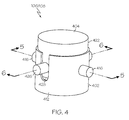
- FIG. 4 is a plan view of an exemplary hydraulic fluid chamber that may be used to implement the system of FIG. 1 ;
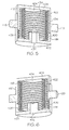
- FIGS. 5 and 6 are cross section views of the exemplary hydraulic fluid chamber taken along lines 5-5 and 6-6, respectively, in FIG. 4 .
- FIG. 1 a schematic representation of an exemplary embodiment of a user interface fluid linkage system 100 is depicted and includes a first user interface 102, a second user interface 104, a first user interface fluid chamber 106, and a second user interface fluid chamber 108.
- the first and second user interfaces 102, 104 are each configured to rotate at least partially, in both a first direction 116 and a second direction 118, around a first axis 120. More specifically, each user interface 102, 104 is responsive to an input force, which may be supplied from a user, to rotate in either the first or second direction 116, 118.
- the system 100 when an input force is supplied to the first or second user interface 102, 104 that causes it to rotate in either the first or second direction 116, 118, the system 100 is configured such that the second or first user interface 104, 102, respectively, will concomitantly be caused to rotate in the first or second direction 116, 118.
- the first and second user interfaces 102, 104 are hydraulically linked via a single, constant volume hydraulic fluid line 110.
- the user interfaces 102, 104 are implemented as linked pilot and co-pilot brake pedals that are configured to rotate only about the first axis 120. In other embodiments, however, the user interfaces 102, 104 may be configured to rotate about two (or more) axes. It may thus be appreciated that the embodiment of FIG. 1 may be used to implement, for example, linked pilot and co-pilot brake pedals.
- first user interface fluid chamber 106 is coupled to the first user interface 102
- second user interface fluid chamber 108 is coupled to the second user interface 104.
- the first and second user interface fluid chambers 106, 108 each include a variable hydraulic fluid volume (not depicted in FIG. 1 ) that are in fluid communication with each other via the hydraulic fluid line 110.
- the first user interface fluid chamber 106 includes a first user interface variable hydraulic fluid volume that varies at least in response to rotation of the first user interface 102 around the first axis 120
- the second user interface fluid chamber 108 includes a second user interface variable hydraulic fluid volume that varies at least in response to rotation of the second user interface 104 around the first axis 120.
- the first and second user interface variable hydraulic fluid volumes will also vary, at least indirectly, in response to rotation of the second and first user interfaces 102, 104, respectively, around the first axis 120.
- the first and second user interface fluid chambers 106, 108 are structurally identical. However, as depicted in FIGS. 2 and 3 respectively, the first fluid chamber 106 and the second fluid chamber 108 are oppositely mounted relative to the first user interface 102 and the second user interface, respectively. The result of this will become more apparent from the following description of an exemplary embodiment of a configuration that may be used to implement the first and second user interface fluid chambers 106, 108.
- the exemplary device is depicted in FIGS. 4-6 , to which reference should now be made.
- first and second user interface fluid chambers 106, 108 may be variously configured, in the depicted embodiment each includes a first mechanism 402, a second mechanism 404, and a bellows 406.
- the first mechanism 402 includes an inner surface 408 and an outer surface 412.
- the first mechanism inner surface 408 defines a first inner volume 414, and a pair of first mount structures 416 extends from the first mechanism outer surface 412.
- the first mechanism 402 further includes a pair of slots 428 (only one depicted in FIG. 4 ) and a fluid port 432. Each slot 428 is formed in the first mechanism 402 and extends between the first mechanism inner and outer surfaces 408, 412.
- the second mechanism 404 is disposed, preferably only partially, within the first inner volume 414, and also includes an inner surface 418 and an outer surface 422.
- the second mechanism inner surface 418 defines a second inner volume 424, and a pair of second mount structures 426 extends from the second mechanism outer surface 422. More specifically, the each of the second mount structures 426 extends through one of the slots 428 formed in the first mechanism 402.
- the bellows 406 which may also be variously configured, is disposed within the first and second inner volumes 414, 424 and is coupled between the first mechanism inner surface 408 and the second mechanism inner surface 418.
- the bellows 406 includes an inner surface 434 that defines the variable hydraulic fluid volume 436.
- the variable hydraulic fluid volume 436 is in fluid communication with the above-mentioned fluid port 432. It may thus be appreciated that the variable volume fluid chamber 436 is in fluid communication with the fluid line 110 via the fluid port 432.
- the first user interface 102 is coupled, via a first connection link 122, to the first mount structures 416 of the first fluid chamber 106
- the second user interface 104 is coupled, via a second connection link 124, to the second mount structures 426 of the second fluid chamber 108.
- the second mount structures 426 of the first user interface fluid chamber 106 are each fixedly coupled relative to the first user interface 102
- the first mount structures 416 of the second user interface fluid chamber 108 are each fixedly coupled relative to the second user interface 104.
- the first user interface variable hydraulic fluid volume 436 will increase.
- hydraulic fluid will be drawn into the first user interface fluid chamber 106 and displaced from the second user interface fluid chamber 108, via the hydraulic line 110.
- the hydraulic fluid displaced from the second user interface fluid chamber 108 will in turn cause the second user interface variable hydraulic fluid volume 436 to decrease.
- the decrease in the second user interface variable hydraulic fluid volume 436 causes the second user interface 104 to be concomitantly rotated in the first direction 116.
- the first user interface variable hydraulic fluid volume 436 will decrease.
- hydraulic fluid will be displaced from the first user interface fluid chamber 106 and directed into the second user interface fluid chamber 108, via the hydraulic line 110.
- the hydraulic fluid directed into the second user interface fluid chamber 108 will in turn cause the second user interface variable hydraulic fluid volume 436 to increase.
- the increase in the second user interface variable hydraulic fluid volume 436 causes the second user interface 104 to be concomitantly rotated in the second direction 118. It is noted that rotation of the second user interface 104 in either the first or second direction 116, 118 would similarly effect movement of the first user interface 102. This is readily apparent to the skilled artisan, and thus this operation is not described in detail.
- the user interface fluid linkage system 100 described herein fluidly links user interfaces 102, 104, such as those used in aircraft flight control systems, via identically configured but oppositely mounted user interface fluid chambers, and via a single, constant volume fluid line.
- the system 100 is relatively less complex, relatively less costly, and relatively more reliable, than current systems.
Landscapes
- Engineering & Computer Science (AREA)
- Aviation & Aerospace Engineering (AREA)
- Mechanical Engineering (AREA)
- Automation & Control Theory (AREA)
- Fluid-Damping Devices (AREA)
- Rehabilitation Tools (AREA)
Applications Claiming Priority (1)
| Application Number | Priority Date | Filing Date | Title |
|---|---|---|---|
| US11/960,326 US20090159756A1 (en) | 2007-12-19 | 2007-12-19 | Aircraft flight control user interface fluid linkage system |
Publications (1)
| Publication Number | Publication Date |
|---|---|
| EP2072394A2 true EP2072394A2 (fr) | 2009-06-24 |
Family
ID=40386194
Family Applications (1)
| Application Number | Title | Priority Date | Filing Date |
|---|---|---|---|
| EP08171017A Withdrawn EP2072394A2 (fr) | 2007-12-19 | 2008-12-08 | Système de liaison hydraulique à interface utilisateur pour la commande du vol d'un avion |
Country Status (2)
| Country | Link |
|---|---|
| US (1) | US20090159756A1 (fr) |
| EP (1) | EP2072394A2 (fr) |
Cited By (1)
| Publication number | Priority date | Publication date | Assignee | Title |
|---|---|---|---|---|
| FR3045007A1 (fr) * | 2015-12-14 | 2017-06-16 | Airbus Operations Sas | Commande d'un aeronef comprenant une pedale accouplee a un verin et dispositif de commandes associe |
Families Citing this family (2)
| Publication number | Priority date | Publication date | Assignee | Title |
|---|---|---|---|---|
| CN103057697B (zh) * | 2013-01-07 | 2015-05-13 | 中国商用飞机有限责任公司 | 一种用于飞机的方向舵脚蹬控制装置和控制方法 |
| CN104590550B (zh) * | 2013-10-30 | 2017-06-20 | 北京精密机电控制设备研究所 | 一种高可靠双冗余电动舵机控制装置 |
Family Cites Families (9)
| Publication number | Priority date | Publication date | Assignee | Title |
|---|---|---|---|---|
| US2397270A (en) * | 1944-02-26 | 1946-03-26 | Adel Prec Products Corp | Hydraulic remote-control system |
| US4470570A (en) * | 1982-09-29 | 1984-09-11 | The Boeing Company | Control assembly for aircraft |
| US5056742A (en) * | 1987-11-13 | 1991-10-15 | The Boeing Company | Modular rudder pedal and brake control assembly for aircraft |
| US5287700A (en) * | 1992-10-14 | 1994-02-22 | Mcdonnell Douglas Helicopter Company | Flexible bellows actuation system |
| FR2756392B1 (fr) * | 1996-11-22 | 1999-01-22 | Aerospatiale | Systeme de couplage de manches de commande |
| DE19754883C2 (de) * | 1997-12-10 | 2002-02-07 | Hyco Pacoma Gmbh | Hydraulische Gleichlaufschaltung mit mindestens einem Hauptzylinder und mindestens einem Folgezylinder |
| US6572055B1 (en) * | 1999-08-10 | 2003-06-03 | Bombardier Aerospace Corporation | Hydrostatic sidestick coupling |
| CA2347556A1 (fr) * | 2001-05-10 | 2002-11-10 | Bombardier Inc. | Inconnu |
| WO2003095259A2 (fr) * | 2002-05-08 | 2003-11-20 | Zhide Feng | Systeme de commande de freinage auxiliaire |
-
2007
- 2007-12-19 US US11/960,326 patent/US20090159756A1/en not_active Abandoned
-
2008
- 2008-12-08 EP EP08171017A patent/EP2072394A2/fr not_active Withdrawn
Cited By (2)
| Publication number | Priority date | Publication date | Assignee | Title |
|---|---|---|---|---|
| FR3045007A1 (fr) * | 2015-12-14 | 2017-06-16 | Airbus Operations Sas | Commande d'un aeronef comprenant une pedale accouplee a un verin et dispositif de commandes associe |
| US10822073B2 (en) | 2015-12-14 | 2020-11-03 | Airbus Operations (S.A.S.) | Aircraft control comprising a pedal coupled to a cylinder and associated control device |
Also Published As
| Publication number | Publication date |
|---|---|
| US20090159756A1 (en) | 2009-06-25 |
Similar Documents
| Publication | Publication Date | Title |
|---|---|---|
| US8078340B2 (en) | Active user interface haptic feedback and linking control system using either force or position data | |
| US7658349B2 (en) | Pilot flight control stick haptic feedback system and method | |
| US7701161B2 (en) | Motor balanced active user interface assembly | |
| US8002220B2 (en) | Rate limited active pilot inceptor system and method | |
| US7759894B2 (en) | Cogless motor driven active user interface haptic feedback system | |
| CN102414081B (zh) | 模块集成式架构的飞行器控制系统 | |
| KR101323836B1 (ko) | 항공기 내의 수동 비행 제어 시스템용 직렬 액츄에이터에 의한 비상 조종 방법 | |
| US8196857B2 (en) | Variable ratio crank for a manual flight control linkage of a rotary wing aircraft | |
| US6446911B1 (en) | Method for controlling actuators on a vehicle | |
| EP1873057B1 (fr) | Mécanisme de palonnier actif avec tolérance de gâche d'objet étranger et frein articulé | |
| US20070235594A1 (en) | Pilot flight control stick feedback system | |
| CN113646191A (zh) | 可空中飞行载具中的脚控制 | |
| EP3699082B1 (fr) | Commande de vol cyclique montée de façon compacte pour giravion | |
| EP2072394A2 (fr) | Système de liaison hydraulique à interface utilisateur pour la commande du vol d'un avion | |
| CN115123520A (zh) | 一种飞机操纵系统的增稳方法 | |
| EP2078997A2 (fr) | Interface homme machine dotée d'une force variable de déblocage nul | |
| US7640743B2 (en) | Aircraft flight control user interface linkage system | |
| US10562609B2 (en) | High trim demand relief | |
| EP3521157B1 (fr) | Systèmes et procédés de commande de vol d'un véhicule aérien | |
| CN111556841B (zh) | 飞机控制系统 | |
| KR20250100584A (ko) | 항공기 제어용 시스템 | |
| WO2025043028A2 (fr) | Manutention au sol d'un engin en utilisant des organes de commande |
Legal Events
| Date | Code | Title | Description |
|---|---|---|---|
| PUAI | Public reference made under article 153(3) epc to a published international application that has entered the european phase |
Free format text: ORIGINAL CODE: 0009012 |
|
| 17P | Request for examination filed |
Effective date: 20081208 |
|
| AK | Designated contracting states |
Kind code of ref document: A2 Designated state(s): AT BE BG CH CY CZ DE DK EE ES FI FR GB GR HR HU IE IS IT LI LT LU LV MC MT NL NO PL PT RO SE SI SK TR |
|
| AX | Request for extension of the european patent |
Extension state: AL BA MK RS |
|
| STAA | Information on the status of an ep patent application or granted ep patent |
Free format text: STATUS: THE APPLICATION HAS BEEN WITHDRAWN |
|
| 18W | Application withdrawn |
Effective date: 20091002 |