EP2072395A2 - Système de commande d'actionnement de surface de commandes de vol électriques à mode d'autorisation complète et d'autorisation limitée - Google Patents
Système de commande d'actionnement de surface de commandes de vol électriques à mode d'autorisation complète et d'autorisation limitée Download PDFInfo
- Publication number
- EP2072395A2 EP2072395A2 EP08170753A EP08170753A EP2072395A2 EP 2072395 A2 EP2072395 A2 EP 2072395A2 EP 08170753 A EP08170753 A EP 08170753A EP 08170753 A EP08170753 A EP 08170753A EP 2072395 A2 EP2072395 A2 EP 2072395A2
- Authority
- EP
- European Patent Office
- Prior art keywords
- flight control
- actuator
- flight
- independent
- commands
- Prior art date
- Legal status (The legal status is an assumption and is not a legal conclusion. Google has not performed a legal analysis and makes no representation as to the accuracy of the status listed.)
- Granted
Links
Images

Classifications
-
- B—PERFORMING OPERATIONS; TRANSPORTING
- B64—AIRCRAFT; AVIATION; COSMONAUTICS
- B64C—AEROPLANES; HELICOPTERS
- B64C13/00—Control systems or transmitting systems for actuating flying-control surfaces, lift-increasing flaps, air brakes, or spoilers
- B64C13/24—Transmitting means
- B64C13/38—Transmitting means with power amplification
- B64C13/50—Transmitting means with power amplification using electrical energy
- B64C13/505—Transmitting means with power amplification using electrical energy having duplication or stand-by provisions
-
- G—PHYSICS
- G05—CONTROLLING; REGULATING
- G05D—SYSTEMS FOR CONTROLLING OR REGULATING NON-ELECTRIC VARIABLES
- G05D1/00—Control of position, course, altitude or attitude of land, water, air or space vehicles, e.g. using automatic pilots
- G05D1/0055—Control of position, course, altitude or attitude of land, water, air or space vehicles, e.g. using automatic pilots with safety arrangements
- G05D1/0061—Control of position, course, altitude or attitude of land, water, air or space vehicles, e.g. using automatic pilots with safety arrangements for transition from automatic pilot to manual pilot and vice versa
Definitions
- the present invention generally relates to aircraft flight control and, more particularly, to a multi-authority mode fly-by-wire flight control surface actuation control system.
- Aircraft typically include a plurality of flight control surfaces that, when controllably positioned, guide the movement of the aircraft from one destination to another.
- the number and type of flight control surfaces included in an aircraft may vary, but typically include both primary flight control surfaces and secondary flight control surfaces.
- the primary flight control surfaces are those that are used to control aircraft movement in the pitch, yaw, and roll axes
- the secondary flight control surfaces are those that are used to influence the lift or drag (or both) of the aircraft.
- the primary flight control surfaces typically include a pair of elevators, a rudder, and a pair of ailerons
- the secondary flight control surfaces typically include a plurality of flaps, slats, and spoilers.
- the positions of the aircraft flight control surfaces are typically controlled using a flight control surface actuation control system.
- the flight control surface actuation control system in response to position commands that originate from either the flight crew or an aircraft autopilot, moves the aircraft flight control surfaces to the commanded positions. In most instances, this movement is effected via actuators that are coupled to the flight control surfaces.
- the position commands that originate from the flight crew are supplied via one or more user interfaces or inceptors.
- inceptors For example, many aircraft include duplicate inceptors, such as yokes and pedals, one set each for the pilot and for the co-pilot. Either of the pilot or co-pilot inceptors can be used to generate desired flight control surface actuator commands.
- a typical fly-by-wire system includes, among other devices, electronic sensors, actuator control units, and flight control modules (FCMs).
- the electronic sensors are coupled to, and sense the positions of, the inceptors, and transmit inceptor position signals to the actuator control units.
- the FCMs receive aircraft state data supplied from various sensors that monitor the state of the aircraft in flight (e.g., inertial sensors and air data sensors).
- the FCMs based at least in part on the aircraft state data, transmit augmentation data to the actuator control units.
- the actuator control units which are sometimes referred to as actuator control electronics (ACEs), generate actuator position commands in response to the inceptor position signals and the augmentation data.
- ACEs actuator control electronics
- the electronic systems and/or sub-systems that are used in aircraft may be subject to various regulatory standards of verification rigor. These standards can prevent or inhibit integration of these electronic systems with other functionalities. These standards can also lead to increased overall implementation costs for such systems, including fly-by-wire systems. There is a desire in the aircraft industry for reduced cost electronic systems, such as fly-by-wire systems. One way of reducing these costs would be to integrate at least portions of the fly-by-wire system with other functionalities. However, presently known fly-by-wire system configurations cannot be integrated with other functionalities and still meet verification rigor standards.
- an aircraft flight control surface actuation control system includes an actuator control unit and a flight control module.
- the actuator control unit includes at least two independent actuator control channels. Each independent actuator control channel is coupled to receive pilot inceptor position signals and flight control augmentation data. Each independent actuator control channel is operable to generate limited authority flight control surface actuator commands based on the pilot inceptor position signals and the flight control augmentation data.
- the flight control module is in operable communication with the actuator control unit. The flight control module is configured to supply the flight control augmentation data to each of the independent actuator control channels, determine operability of each of the actuator control channels, and, based on the determined operability of each independent actuator control channel, to selectively prevent one of the independent actuator control channels from supplying the limited authority flight control surface actuator commands.
- an aircraft flight control surface actuation control system includes an actuator control unit, a flight control module, and a mode select switch.
- the actuator control unit is coupled to receive pilot inceptor position signals and flight control augmentation data.
- the actuator control unit is operable to generate limited authority flight control surface actuator commands based on the pilot inceptor position signals and the flight control augmentation data.
- the flight control module is in operable communication with the actuator control unit, and is operable to supply the flight control augmentation data to the actuator control unit, at least selectively generate full authority flight control surface actuator commands, and supply a mode select control signal.
- the mode select switch is coupled to receive the limited authority flight control surface actuator commands, the full authority flight control surface actuator commands, and the mode select control signal.
- the mode select switch is operable, in response to the mode select control signal, to supply either the limited authority flight control actuator commands or the full authority flight control surface actuator commands.
- FIG. 1 is a perspective view of an exemplary fixed-wing aircraft depicting primary and secondary flight control surfaces
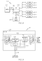
- FIG. 2 is a simplified functional block diagram of an exemplary flight control surface actuation control system
- FIG. 3 is a functional block diagram of a single independent actuator control channel that may be used to implement the actuator control unit depicted in FIG. 2 .
- the aircraft 100 includes first and second horizontal stabilizers 101-1 and 101-2, respectively, a vertical stabilizer 103, and first and second wings 105-1 and 105-2, respectively.
- An elevator 102 is disposed on each horizontal stabilizer 101-1, 101-2
- a rudder 104 is disposed on the vertical stabilizer 103
- an aileron 106 is disposed on each wing 105-1, 105-2.
- a plurality of flaps 108, slats 112, and spoilers 114 are disposed on each wing 105-1, 105-2.
- the elevators 102, the rudder 104, and the ailerons 106 are typically referred to as the primary flight control surfaces, and the flaps 108, the slats 112, and the spoilers 114 are typically referred to as the secondary flight control surfaces.
- the primary flight control surfaces 102-106 control aircraft movements about the aircraft pitch, yaw, and roll axes.
- the elevators 102 are used to control aircraft movement about the pitch axis
- the rudder 104 is used to control aircraft movement about the yaw axis
- the ailerons 106 control aircraft movement about the roll axis. It is noted, however, that aircraft movement about the yaw axis can also be achieved by varying the thrust levels from the engines on opposing sides of the aircraft 100.
- the secondary control surfaces 108-114 influence the lift and drag of the aircraft 100.
- the flaps 108 and slats 112 may be moved from retracted positions to extended positions. In the extended position, the flaps 108 increase both lift and drag, and enable the aircraft 100 to descend at a lower airspeed, and also enable the aircraft 100 get airborne over a shorter distance.
- the slats 112, in the extended position increase lift, and are typically used in conjunction with the flaps 108.
- the spoilers 114 reduce lift and when moved from retracted positions to extended positions, which is typically done during aircraft landing operations, may be used as air brakes to assist in slowing the aircraft 100.
- the flight control surfaces 102-114 are moved to commanded positions via a flight control surface actuation control system 200, an exemplary embodiment of which is shown in FIG. 2 .
- the flight control surface actuation system 200 includes an inceptor 202, an actuator control unit 204, a flight control module 206, and a plurality of flight control surface actuators 208.
- the system 200 includes a plurality of inceptors 202, a plurality of actuator control units 204, and a plurality of flight control modules 206.
- the inceptor 202 is configured to move in response to an input force supplied from, for example, a pilot.
- One or more non-illustrated position sensors sense the position of the inceptor 202, and supply inceptor position signals 212 representative of the sensed inceptor position.
- the inceptor 202 may be implemented using any one of numerous inceptor configurations including, for example, a side stick, a yoke, or a rudder pedal, just to name a few. It will additionally be appreciated that the inceptor 202 may be implemented as an active inceptor or a passive inceptor. No matter its specific implementation, the inceptor 202 supplies the inceptor position signals 212 to the actuator control unit 204.
- the actuator control unit 204 which may also be referred to as an actuator control electronics (ACE) unit, is preferably implemented with a plurality of independent actuator control channels 214. It will be appreciated that the number of independent actuator control channels may vary, but in the depicted embodiment the actuator control unit 204 includes two independent actuator control channels 214 (e.g., 214-1, 214-2). In any case, each independent actuator control channel 214 is coupled to receive the pilot inceptor position signals 212 from the pilot inceptor 202, and flight control augmentation data 216 that are supplied from the flight control module 206. Each independent actuator control channel 214 is also preferably configured to control multiple actuators.
- ACE actuator control electronics
- each independent actuator control channel 214 is preferably configured to control one pitch axis flight control surface actuator 208-P (e.g., elevator actuator), one yaw axis flight control surface actuator 208-Y (e.g., rudder actuator), and one roll axis flight control surface actuator 208-R (e.g., aileron actuator).
- each actuator control channel 214 is configured to generate flight control surface actuator commands either based on the pilot inceptor position signals 212 and the flight control augmentation data 216, or based on only the pilot inceptor position signals 212.
- the actuator control channels 214 generate the flight control surface actuator commands based on both the inceptor position signals 212 and the flight control augmentation data 216.
- the flight control augmentation data 216 that are supplied from the flight control module 206 augment the direct commands supplied from the pilot via the pilot inceptor 202 to smooth the flight of the aircraft. More specifically, when the actuator control channels 214 process the pilot inceptor position signals 212 and the flight control augmentation data 216, the flight control surface actuator commands that each channel 214 generates will ensure a smooth flight, enhance aircraft handling characteristics, and provide flight envelope protection. It may thus be appreciated that the flight control surface actuator commands that the actuator control channels 214 generate during normal system 200 operations are referred to herein as limited authority flight control surface actuator commands.
- the actuator control channels 214 will generate the flight control surface actuator commands based solely on the inceptor position signals 212. It is noted that this operational configuration is sometimes referred to as "direct mode" operation. It will be appreciated that the flight control augmentation data 216 may become unavailable, for example, in the highly unlikely event that the flight control module 206 was to become unavailable or otherwise inoperable. No matter the specific cause of such an highly unlikely event, because the flight control surface actuator commands that the actuator control channels 214 generate are no longer augmented, the commands are referred to herein as direct flight control surface actuator commands.
- each independent actuator control channel 214 preferably includes two identical (or at least substantially identical) processing lanes, a command lane 302 and a monitor lane 304.
- This architecture ensures, among other things, that each independent actuator control channel 214 implements a fail-passive functionality.
- the command and monitor processing lanes 302, 304 each include one or more inceptor demodulators 306, computational logic 308, and one or more output drives 312.
- the inceptor demodulators 306 are each coupled to receive and demodulate the inceptor position signals 212, and are each configured to supply appropriately conditioned pilot command signals to the computational logic 308.
- the command and monitor lanes 302, 304 each include three intercept demodulators 306 (e.g., 306-1, 306-2, 306-3), one associated with each of the each controllable axis (e.g., pitch, yaw, roll). It will also be appreciated that this number of inceptor demodulators 306 may vary.
- the computational logic 308 is coupled to receive the conditioned pilot signals from each of the inceptor demodulators 306, and the flight control augmentation data 216 from the flight control module 206.
- the computational logic 308, based on the conditioned pilot signals and the flight control augmentation data 216, calculates the appropriate flight control surface actuator commands.
- the computational logic 308 calculates limited authority flight control surface actuator commands.
- the computational logic 308 calculates the above-described direct flight control surface actuator commands.
- computational logic 308 may be implemented using various types and combinations of hardware, software, and firmware including, for example, suitable analog-to-digital conversion devices, digital-to-analog conversion devices, microprocessors, digital signal processors (DSPs), and programmable logic devices (PLDs).
- suitable analog-to-digital conversion devices digital-to-analog conversion devices
- microprocessors digital signal processors (DSPs)
- DSPs digital signal processors
- PLDs programmable logic devices
- each independent actuator control channel 214 is at least partially implemented with dissimilar hardware. That is, at least those portions of the computational logic 308 in each independent actuator control channel 214 that calculate the flight control surface actuator commands are implemented with devices that are designed and manufactured by different manufacturers. This mitigates the highly unlikely, yet postulated occurrence of a simultaneous generic fault in each independent actuator control channel 214.
- the actuator control unit 204 meets the standards for so-called "complex" devices as defined by DO-254.
- the computational logic 308 in the command and monitor processing lanes 302, 304 of an actuator control channel 214 need not be dissimilar, it is just the computational logic 308 between each independent actuator control channel 214 that is preferably dissimilar.
- the flight control surface actuator commands that are computed in the computational logic 308 are supplied to the output drives 312.
- the output drives 312 appropriately amplify and condition the flight control surface actuator commands for transmission to the appropriate flight control surface actuators 208.
- the command and monitor lanes 302, 304 each include three output drives 312 (e.g., 312-1, 312-2, 312-3), one associated with each of the each controllable axis (e.g., pitch, yaw, roll). It will also be appreciated that this number of output drives 312 may vary.
- each independent actuator control channel 214 may also include a mode select switch 314 and an augmentation on/off switch 316.
- the purpose and function of the mode select switch 314 and the augmentation on/off switch 316 will be described in greater detail further below. It will be appreciated that the mode select switches 314 and the augmentation on/off switches 316, though depicted and described herein as a separate device within each independent actuator control channel 214, could be implemented as part of the computational logic 308. Moreover, the mode select switches 314 and the augmentation on/off switches 316 could be implemented apart from the actuator control unit 204.
- mode select switch 314 and the augmentation on/off switches 316 could be implemented using any one of numerous suitable devices for carrying out the functions that are described further below.
- the mode select switch 314 and the augmentation on/off switch 316 could be implemented using hardware, software, firmware, or various combinations thereof.
- the flight control module 206 is in operable communication with the actuator control unit 204 via, for example, a suitable communication bus 218.
- the flight control module 206 is also coupled, via the same or a separate communication bus 218, to receive data representative of various aircraft conditions. These data may include, for example, various inertial and navigation data from non-illustrated sensors and avionics equipment. Some exemplary data include air speed, altitude, attitude, weather conditions, location, and heading, just to name a few.
- the flight control module 206 in response to these data, generates the flight control augmentation data 216 that are supplied to the actuator control unit 204.
- the flight control module 206 is configured to determine the operability of each of the independent actuator control channels 214. Based on the determined operability of each independent actuator control channel 214, the flight control module 206 may selectively prevent one of the independent actuator control channels 214 from supplying limited authority flight control surface actuator commands to the associated flight control surface actuators 208.
- the manner in which the flight control module 206 determines the operability of each independent actuator control channel 214 may vary. However, in the depicted embodiment the flight control module 206 independently computes limited authority flight control surface actuator commands, and compares the commands it computes to the commands that are computed by the computational logic 308 in each independent actuator control channel 214.
- the flight control module 206 receives the conditioned pilot signals from the inceptor demodulators 306 in each actuator control channel 214, and the limited authority flight control surface actuator commands computed by the computational logic 308 in each actuator control channel 214 (see FIG. 3 ).
- the flight control module 206 using the conditioned pilot signals and the flight control augmentation data 216 that it generates, independently calculates limited authority flight control surface actuator commands.
- the flight control module 206 then compares the limited authority flight control surface actuator commands it computes to those that are computed by the computational logic 308 in each independent actuator control channel 214.
- the flight control module 206 will prevent the faulty, unavailable, or otherwise inoperable actuator control channel 214 from supplying the limited authority flight control surface actuator commands to the associated flight control surface actuators 208
- the flight control system 200 may also be configured such that, in some instances, the flight control surface actuator commands supplied to the flight control surface actuators 208 may be based on the limited authority flight control surface commands calculated by the flight control module 206. It is noted that the flight control surface actuator commands that the flight control module 206 calculates during these instances are referred to herein as full authority flight control surface actuator commands, and the flight control system operational mode may be referred to as full authority mode. This is because the flight control module 206, during these instances, is not supplying flight control augmentation data 216 to the actuator control unit 204 and comparing independently calculated flight control surface actuator commands to those calculated in the actuator control unit 204.
- the flight control module 206 is actually calculating the flight control surface actuator commands that are used to move the flight control surface actuators 208 to the commanded positions.
- the circumstances under which the flight control system 200 is switched to operation in the full authority mode may vary, but it is preferably done so in response to a relatively highly unlikely event.
- the flight control module 206 may determine, based on various inputs, that the aircraft is in, or is about to be placed in, an undesirable attitude or other configuration, and switch momentarily to the full authority mode to correct the configuration.
- the full authority flight control surface actuator commands could be supplied directly from the flight control module 206 to the flight control surface actuators 208.
- the flight control module 206 would include its own independent set of actuator drives.
- the full authority flight control surface actuator commands are supplied to the flight control surface actuators 208 via the mode select switch 314 in each of the independent actuator control channels 214.
- the augmentation on/off switch 316 prohibits the augmentation data from being supplied to each of the independent actuator control channels 214.
- each mode select switch 314 is coupled to receive the limited authority flight control surface actuator commands calculated in its independent actuator control channel 214, the full authority flight control surface actuator commands calculated in the flight control module 206, and a mode select control signal 318 from the flight control module 206.
- the mode select switches 314 are operable, in response to the mode select control signal 318, to supply either the limited authority flight control surface actuator commands or the full authority flight control surface actuator commands to the appropriate output drives 312 for subsequent supply to the appropriate flight control surface actuators 208.
- the augmentation on/off switches 316 also receive the mode select control signal 318 and, in response, either allow or prohibit the augmentation data from being supplied to the computational logic 308.
- the above-described ACE 204 and FCM 206 configurations allow the flight control system 200 to be variously configured and variously operated.
- the flight control system 200 may be configured to operate in what are referred to herein as a limited authority configuration, a full authority configuration, or a limited authority/short-term full authority configuration.
- a limited authority configuration a full authority configuration
- a limited authority/short-term full authority configuration a limited authority/short-term full authority configuration
- the mode select control signal 318 supplied from the flight control module 206 will cause the mode select switches 314 to always receive flight control surface actuator commands from the computation logic 308.
- the flight control surface actuator commands supplied from the mode select switches 314 to the output drives 312 may be either limited authority flight control surface actuator commands or direct flight control surface actuator commands.
- the mode select control signal 318 supplied from the flight control module 206 will cause the augmentation data on/off switches 316 to supply the augmentation data to the computational logic 308.
- the flight control surface actuator commands will normally be limited authority flight control surface actuator commands.
- the flight control module 206 (or other circuit or device) determines that augmentation data need not or should not be supplied to the computational logic 308, then the mode select control signal 318 supplied from the flight control module 206 will cause augmentation data on/off switches 316 to be in a position in which the augmentation data are not supplied to the computational logic 308. As a result, the flight control surface actuator commands will be direct flight control surface actuator commands.
- the mode select control signal 318 supplied from the flight control module 206 will cause the augmentation data on/off switches 316 to always be in a position in which the augmentation data are not supplied to the computational logic 308.
- the flight control surface actuator commands supplied from the mode select switches 314 to the output drives 312 may be either full authority flight control surface actuator commands or direct flight control surface actuator commands.
- the mode select control signal 318 supplied from the flight control module 206 will cause the mode select switches 314 to receive full authority flight control surface actuator commands from the flight control module 206.
- the flight control module 206 (or other circuit or device) determines that full authority flight control surface actuator commands need not or should not be supplied, then the mode select control signal 318 supplied from the flight control module 206 will cause the mode select switches 314 to be in a position in which the mode select switches 314 receive direct flight control surface actuator commands from the computational logic 308.
- the mode select control signal 318 supplied from the flight control module 206 will normally cause the mode select switches 314 to receive flight control surface actuator commands from the computational logic 308, and the augmentation data on/off switches 316 to be in positions to supply the augmentation to the computational logic 308.
- limited authority flight control surface actuator commands are normally supplied to the output drives 312.
- the flight control module 206 (or other circuit or device) determines that the full authority flight control surface actuator commands need to be supplied to the flight control surface actuators 208, the flight control module 206 will supply the appropriate mode select control signal 318 to the mode select switches 314 and the augmentation on/off switches 316, to at least temporarily supply full authority flight control surface actuator commands to the output drives 312.
Landscapes
- Engineering & Computer Science (AREA)
- Automation & Control Theory (AREA)
- Aviation & Aerospace Engineering (AREA)
- Radar, Positioning & Navigation (AREA)
- Remote Sensing (AREA)
- Physics & Mathematics (AREA)
- General Physics & Mathematics (AREA)
- Control Of Position, Course, Altitude, Or Attitude Of Moving Bodies (AREA)
Applications Claiming Priority (1)
| Application Number | Priority Date | Filing Date | Title |
|---|---|---|---|
| US11/957,665 US7840316B2 (en) | 2007-12-17 | 2007-12-17 | Limited authority and full authority mode fly-by-wire flight control surface actuation control system |
Publications (3)
| Publication Number | Publication Date |
|---|---|
| EP2072395A2 true EP2072395A2 (fr) | 2009-06-24 |
| EP2072395A3 EP2072395A3 (fr) | 2012-10-03 |
| EP2072395B1 EP2072395B1 (fr) | 2014-04-16 |
Family
ID=40386189
Family Applications (1)
| Application Number | Title | Priority Date | Filing Date |
|---|---|---|---|
| EP08170753.1A Ceased EP2072395B1 (fr) | 2007-12-17 | 2008-12-04 | Système de commande d'actionnement des surfaces de commande de vol à mode d'autorisation complète et d'autorisation limitée |
Country Status (2)
| Country | Link |
|---|---|
| US (1) | US7840316B2 (fr) |
| EP (1) | EP2072395B1 (fr) |
Cited By (5)
| Publication number | Priority date | Publication date | Assignee | Title |
|---|---|---|---|---|
| WO2011095360A1 (fr) * | 2010-02-05 | 2011-08-11 | Airbus Operations Gmbh | Avion doté d'un dispositif de régulation de débit |
| DE102011115362A1 (de) * | 2011-10-07 | 2013-04-11 | Liebherr-Aerospace Lindenberg Gmbh | Modulares elektronisches Flugsteuerungssystem |
| GB2569601A (en) * | 2017-12-21 | 2019-06-26 | Bae Systems Plc | Aircraft control systems |
| US11174005B2 (en) | 2017-12-21 | 2021-11-16 | Bae Systems Plc | Aircraft control systems |
| DE102023133936A1 (de) | 2023-12-05 | 2025-06-05 | Liebherr-Aerospace Lindenberg Gmbh | Steuereinheit, System und Verfahren |
Families Citing this family (17)
| Publication number | Priority date | Publication date | Assignee | Title |
|---|---|---|---|---|
| JP5489708B2 (ja) * | 2009-12-28 | 2014-05-14 | ナブテスコ株式会社 | アクチュエータ制御システム |
| US9870000B2 (en) * | 2011-03-28 | 2018-01-16 | Honeywell International Inc. | Methods and systems for translating an emergency system alert signal to an automated flight system maneuver |
| US8534599B2 (en) * | 2011-03-31 | 2013-09-17 | Hamilton Sundstrand Corporation | Redundant two stage electro-hydraulic servo actuator control |
| US8935015B2 (en) | 2011-05-09 | 2015-01-13 | Parker-Hannifin Corporation | Flight control system with alternate control path |
| US9354635B2 (en) * | 2012-06-05 | 2016-05-31 | Textron Innovations Inc. | Takeoff/landing touchdown protection management system |
| US9033284B2 (en) * | 2012-11-20 | 2015-05-19 | Sikorsky Aircraft Corporation | Integrated seat mounted inceptor |
| US9870004B2 (en) | 2014-05-21 | 2018-01-16 | Bell Helicopter Textron Inc. | High authority stability and control augmentation system |
| US9493231B2 (en) * | 2015-03-20 | 2016-11-15 | The Boeing Company | Flight control system command selection and data transport |
| US10752339B2 (en) * | 2016-03-18 | 2020-08-25 | The Boeing Company | Customizing aircraft performance systems and methods |
| WO2018118070A1 (fr) | 2016-12-22 | 2018-06-28 | Kitty Hawk Corporation | Système de commande répartie de vol |
| US9908616B1 (en) * | 2017-05-12 | 2018-03-06 | Kitty Hawk Corporation | Geometry-based flight control system |
| US11435761B1 (en) | 2021-07-23 | 2022-09-06 | Beta Air, Llc | System and method for distributed flight control system for an electric vehicle |
| US11465734B1 (en) | 2021-09-16 | 2022-10-11 | Beta Air, Llc | Systems and methods for distrubuted flight controllers for redundancy for an electric aircraft |
| US11427305B1 (en) | 2021-09-16 | 2022-08-30 | Beta Air, Llc | Methods and systems for flight control for managing actuators for an electric aircraft |
| US20240092476A1 (en) * | 2022-09-21 | 2024-03-21 | Gulfstream Aerospace Corporation | Temporary backup control methodology for an inceptor of a vehicle |
| US12366464B2 (en) | 2023-02-06 | 2025-07-22 | Honeywell International, Inc. | Aircraft flight control surface position sensing system |
| US20240308648A1 (en) * | 2023-03-16 | 2024-09-19 | Honeywell International Inc. | Fly-by-wire flight control system with back-up control in an inceptor |
Citations (1)
| Publication number | Priority date | Publication date | Assignee | Title |
|---|---|---|---|---|
| US20060214066A1 (en) | 2002-03-28 | 2006-09-28 | Yount Larry J | Methods and apparatus for error-tolerant wrap-back ACE monitor |
Family Cites Families (16)
| Publication number | Priority date | Publication date | Assignee | Title |
|---|---|---|---|---|
| US7017861B1 (en) * | 2000-05-22 | 2006-03-28 | Saab Ab | Control system for actuators in an aircraft |
| FR2809372B1 (fr) * | 2000-05-29 | 2002-09-20 | Aerospatiale Matra Airbus | Aeronef a commandes de vol electriques, pourvu d'un pilote automatique |
| US6443399B1 (en) * | 2000-07-14 | 2002-09-03 | Honeywell International Inc. | Flight control module merged into the integrated modular avionics |
| US6561463B1 (en) * | 2000-07-14 | 2003-05-13 | Honeywell International Inc. | Flight control module with integrated spoiler actuator control electronics |
| US6366837B1 (en) * | 2000-07-14 | 2002-04-02 | Honeywell International Inc. | Method for providing command augmentation to a command lane within a vehicle |
| JP3751559B2 (ja) * | 2001-12-26 | 2006-03-01 | ナブテスコ株式会社 | 飛行制御システム |
| FR2835067B1 (fr) * | 2002-01-21 | 2004-04-02 | Trw Sys Aeronautiques Civil | Dispositif de commande a boucle d'asservissement, notamment actionneur electro-hydraulique de commande de vol |
| US20040078120A1 (en) * | 2002-10-16 | 2004-04-22 | Edgar Melkers | Non-linear compensation of a control system having an actuator and a method therefore |
| US7209809B2 (en) * | 2003-10-15 | 2007-04-24 | The Boeing Company | Method and apparatus for obtaining high integrity and availability in multi-channel systems |
| US7770842B2 (en) * | 2004-08-24 | 2010-08-10 | Honeywell International Inc. | Aircraft flight control surface actuation system communication architecture |
| US7337044B2 (en) | 2004-11-10 | 2008-02-26 | Thales Canada Inc. | Dual/triplex flight control architecture |
| US7789345B2 (en) * | 2005-03-03 | 2010-09-07 | Nabtesco Corporation | Actuator control apparatus |
| US20070007385A1 (en) * | 2005-06-27 | 2007-01-11 | Honeywell International, Inc. | Electric flight control surface actuation system electronic architecture |
| US7421320B2 (en) * | 2005-10-06 | 2008-09-02 | The Boeing Company | Methods and apparatus for implementing mid-value selection functions for dual dissimlar processing modules |
| US7556224B2 (en) * | 2005-12-27 | 2009-07-07 | Honeywell International Inc. | Distributed flight control surface actuation system |
| CA2637226A1 (fr) * | 2006-01-17 | 2007-07-26 | Gulfstream Aerospace Corporation | Appareil et procede de commande de secours utilises dans un systeme de commande de vol distribue |
-
2007
- 2007-12-17 US US11/957,665 patent/US7840316B2/en not_active Expired - Fee Related
-
2008
- 2008-12-04 EP EP08170753.1A patent/EP2072395B1/fr not_active Ceased
Patent Citations (1)
| Publication number | Priority date | Publication date | Assignee | Title |
|---|---|---|---|---|
| US20060214066A1 (en) | 2002-03-28 | 2006-09-28 | Yount Larry J | Methods and apparatus for error-tolerant wrap-back ACE monitor |
Cited By (7)
| Publication number | Priority date | Publication date | Assignee | Title |
|---|---|---|---|---|
| WO2011095360A1 (fr) * | 2010-02-05 | 2011-08-11 | Airbus Operations Gmbh | Avion doté d'un dispositif de régulation de débit |
| US9573678B2 (en) | 2010-02-05 | 2017-02-21 | Airbus Operations Gmbh | Aircraft with a control device |
| DE102011115362A1 (de) * | 2011-10-07 | 2013-04-11 | Liebherr-Aerospace Lindenberg Gmbh | Modulares elektronisches Flugsteuerungssystem |
| GB2569601A (en) * | 2017-12-21 | 2019-06-26 | Bae Systems Plc | Aircraft control systems |
| US11174005B2 (en) | 2017-12-21 | 2021-11-16 | Bae Systems Plc | Aircraft control systems |
| GB2569601B (en) * | 2017-12-21 | 2022-05-11 | Bae Systems Plc | Aircraft control systems |
| DE102023133936A1 (de) | 2023-12-05 | 2025-06-05 | Liebherr-Aerospace Lindenberg Gmbh | Steuereinheit, System und Verfahren |
Also Published As
| Publication number | Publication date |
|---|---|
| EP2072395A3 (fr) | 2012-10-03 |
| EP2072395B1 (fr) | 2014-04-16 |
| US20090152404A1 (en) | 2009-06-18 |
| US7840316B2 (en) | 2010-11-23 |
Similar Documents
| Publication | Publication Date | Title |
|---|---|---|
| EP2072395B1 (fr) | Système de commande d'actionnement des surfaces de commande de vol à mode d'autorisation complète et d'autorisation limitée | |
| US7658349B2 (en) | Pilot flight control stick haptic feedback system and method | |
| US8078340B2 (en) | Active user interface haptic feedback and linking control system using either force or position data | |
| EP2134598B1 (fr) | Algorithme de commande de parcours de vol et de vitesse verticale pour un déplacement collectif utilisant une file d'attente tactile et des retours tactiles | |
| EP2052966B1 (fr) | Système et procédé d'interface actif de pilotage à limitation de taux de variation | |
| EP1301393B1 (fr) | Modules de commande de vol fusionnes avec une aeroelectronique modulaire integree | |
| EP1301835B1 (fr) | Module des commandes de vol avec electronique integree de commande de l'actionneur du deporteur | |
| EP2142427B1 (fr) | Algorithme de maintien de vitesse à commandes d'assiette de vol et d'accélération pour giravions à gamme étendue du centre de gravité | |
| US12006023B2 (en) | Aircraft inceptor apparatus and aircraft flight control system | |
| US5404305A (en) | Control of pilot control station authority for a dual piloted flight control system | |
| CN105366036B (zh) | 用于在电传操纵飞行器系统中进行操纵器控制的系统 | |
| WO2009030005A2 (fr) | Systèmes de protection contre le décrochage, le tremblement et l'assiette élevée | |
| EP0743244B1 (fr) | Système de protection contre survitesse pour autopilote/directeur de vol | |
| US20020002428A1 (en) | Aricraft with electrical fly-by-wire controls, equipped with an automatic pilot | |
| EP2078997A2 (fr) | Interface homme machine dotée d'une force variable de déblocage nul | |
| RU2327602C1 (ru) | Способ управления самолетом и комплексная система для его осуществления | |
| EP1781538B1 (fr) | Architecture de communication du systeme d'actionnement de la gouverne d'un avion |
Legal Events
| Date | Code | Title | Description |
|---|---|---|---|
| PUAI | Public reference made under article 153(3) epc to a published international application that has entered the european phase |
Free format text: ORIGINAL CODE: 0009012 |
|
| 17P | Request for examination filed |
Effective date: 20081204 |
|
| AK | Designated contracting states |
Kind code of ref document: A2 Designated state(s): AT BE BG CH CY CZ DE DK EE ES FI FR GB GR HR HU IE IS IT LI LT LU LV MC MT NL NO PL PT RO SE SI SK TR |
|
| AX | Request for extension of the european patent |
Extension state: AL BA MK RS |
|
| PUAL | Search report despatched |
Free format text: ORIGINAL CODE: 0009013 |
|
| AK | Designated contracting states |
Kind code of ref document: A3 Designated state(s): AT BE BG CH CY CZ DE DK EE ES FI FR GB GR HR HU IE IS IT LI LT LU LV MC MT NL NO PL PT RO SE SI SK TR |
|
| AX | Request for extension of the european patent |
Extension state: AL BA MK RS |
|
| RIC1 | Information provided on ipc code assigned before grant |
Ipc: G05D 1/00 20060101ALI20120829BHEP Ipc: B64C 13/50 20060101AFI20120829BHEP |
|
| 17Q | First examination report despatched |
Effective date: 20120918 |
|
| AKX | Designation fees paid |
Designated state(s): DE FR GB |
|
| GRAP | Despatch of communication of intention to grant a patent |
Free format text: ORIGINAL CODE: EPIDOSNIGR1 |
|
| INTG | Intention to grant announced |
Effective date: 20140103 |
|
| GRAS | Grant fee paid |
Free format text: ORIGINAL CODE: EPIDOSNIGR3 |
|
| GRAA | (expected) grant |
Free format text: ORIGINAL CODE: 0009210 |
|
| AK | Designated contracting states |
Kind code of ref document: B1 Designated state(s): DE FR GB |
|
| REG | Reference to a national code |
Ref country code: GB Ref legal event code: FG4D |
|
| REG | Reference to a national code |
Ref country code: DE Ref legal event code: R096 Ref document number: 602008031508 Country of ref document: DE Effective date: 20140605 |
|
| REG | Reference to a national code |
Ref country code: DE Ref legal event code: R097 Ref document number: 602008031508 Country of ref document: DE |
|
| PLBE | No opposition filed within time limit |
Free format text: ORIGINAL CODE: 0009261 |
|
| STAA | Information on the status of an ep patent application or granted ep patent |
Free format text: STATUS: NO OPPOSITION FILED WITHIN TIME LIMIT |
|
| 26N | No opposition filed |
Effective date: 20150119 |
|
| REG | Reference to a national code |
Ref country code: DE Ref legal event code: R097 Ref document number: 602008031508 Country of ref document: DE Effective date: 20150119 |
|
| REG | Reference to a national code |
Ref country code: FR Ref legal event code: PLFP Year of fee payment: 8 |
|
| REG | Reference to a national code |
Ref country code: FR Ref legal event code: PLFP Year of fee payment: 9 |
|
| REG | Reference to a national code |
Ref country code: FR Ref legal event code: PLFP Year of fee payment: 10 |
|
| PGFP | Annual fee paid to national office [announced via postgrant information from national office to epo] |
Ref country code: FR Payment date: 20181231 Year of fee payment: 11 Ref country code: GB Payment date: 20181221 Year of fee payment: 11 |
|
| PGFP | Annual fee paid to national office [announced via postgrant information from national office to epo] |
Ref country code: DE Payment date: 20190228 Year of fee payment: 11 |
|
| REG | Reference to a national code |
Ref country code: DE Ref legal event code: R119 Ref document number: 602008031508 Country of ref document: DE |
|
| GBPC | Gb: european patent ceased through non-payment of renewal fee |
Effective date: 20191204 |
|
| PG25 | Lapsed in a contracting state [announced via postgrant information from national office to epo] |
Ref country code: FR Free format text: LAPSE BECAUSE OF NON-PAYMENT OF DUE FEES Effective date: 20191231 Ref country code: GB Free format text: LAPSE BECAUSE OF NON-PAYMENT OF DUE FEES Effective date: 20191204 Ref country code: DE Free format text: LAPSE BECAUSE OF NON-PAYMENT OF DUE FEES Effective date: 20200701 |
|
| P01 | Opt-out of the competence of the unified patent court (upc) registered |
Effective date: 20230525 |