EP2072398A2 - Gondelanordnung mit Einlassentlüftung - Google Patents
Gondelanordnung mit Einlassentlüftung Download PDFInfo
- Publication number
- EP2072398A2 EP2072398A2 EP08253891A EP08253891A EP2072398A2 EP 2072398 A2 EP2072398 A2 EP 2072398A2 EP 08253891 A EP08253891 A EP 08253891A EP 08253891 A EP08253891 A EP 08253891A EP 2072398 A2 EP2072398 A2 EP 2072398A2
- Authority
- EP
- European Patent Office
- Prior art keywords
- opening
- turbine engine
- engine
- interior surface
- cowl
- Prior art date
- Legal status (The legal status is an assumption and is not a legal conclusion. Google has not performed a legal analysis and makes no representation as to the accuracy of the status listed.)
- Withdrawn
Links
Images

Classifications
-
- B—PERFORMING OPERATIONS; TRANSPORTING
- B64—AIRCRAFT; AVIATION; COSMONAUTICS
- B64D—EQUIPMENT FOR FITTING IN OR TO AIRCRAFT; FLIGHT SUITS; PARACHUTES; ARRANGEMENT OR MOUNTING OF POWER PLANTS OR PROPULSION TRANSMISSIONS IN AIRCRAFT
- B64D33/00—Arrangement in aircraft of power plant parts or auxiliaries not otherwise provided for
- B64D33/02—Arrangement in aircraft of power plant parts or auxiliaries not otherwise provided for of combustion air intakes
-
- B—PERFORMING OPERATIONS; TRANSPORTING
- B64—AIRCRAFT; AVIATION; COSMONAUTICS
- B64D—EQUIPMENT FOR FITTING IN OR TO AIRCRAFT; FLIGHT SUITS; PARACHUTES; ARRANGEMENT OR MOUNTING OF POWER PLANTS OR PROPULSION TRANSMISSIONS IN AIRCRAFT
- B64D33/00—Arrangement in aircraft of power plant parts or auxiliaries not otherwise provided for
- B64D33/02—Arrangement in aircraft of power plant parts or auxiliaries not otherwise provided for of combustion air intakes
- B64D2033/0226—Arrangement in aircraft of power plant parts or auxiliaries not otherwise provided for of combustion air intakes comprising boundary layer control means
-
- B—PERFORMING OPERATIONS; TRANSPORTING
- B64—AIRCRAFT; AVIATION; COSMONAUTICS
- B64D—EQUIPMENT FOR FITTING IN OR TO AIRCRAFT; FLIGHT SUITS; PARACHUTES; ARRANGEMENT OR MOUNTING OF POWER PLANTS OR PROPULSION TRANSMISSIONS IN AIRCRAFT
- B64D33/00—Arrangement in aircraft of power plant parts or auxiliaries not otherwise provided for
- B64D33/02—Arrangement in aircraft of power plant parts or auxiliaries not otherwise provided for of combustion air intakes
- B64D2033/0266—Arrangement in aircraft of power plant parts or auxiliaries not otherwise provided for of combustion air intakes specially adapted for particular type of power plants
- B64D2033/0286—Arrangement in aircraft of power plant parts or auxiliaries not otherwise provided for of combustion air intakes specially adapted for particular type of power plants for turbofan engines
Definitions
- This invention relates to a nacelle assembly for a turbine engine, particularly for an aircraft.
- a gas turbine engine such as a turbo fan engine
- air is pressurized in a compressor and mixed with fuel in a combustor to generate hot combustion gases. These gases flow downstream through the turbine stages of the engine, which extract energy from the gases.
- a high pressure turbine powers a high pressure compressor
- a low pressure turbine powers the fan section disposed upstream of the compressor and a low pressure compressor.
- Combustion gases are discharged from the turbo fan engine through a core exhaust nozzle while fan air is discharged through an annular fan exhaust nozzle defined at least partially by a nacelle surrounding the core engine.
- a majority of the propulsion thrust is provided by the pressurized fan air, which is discharged through the fan exhaust nozzle.
- the remaining thrust is provided by the combustion gases discharged through the core exhaust nozzle.
- An inlet lip section located at the foremost edge of the turbo fan nacelle is typically designed to enable operation of the turbo fan engine and prevent the separation of airflow from the inlet lip section of the nacelle during these diverse flight conditions.
- the inlet lip section requires a "thick" inlet lip section designed to support operation of the turbo fan during specific flight conditions, such as cross-wind conditions, take-off and the like.
- the "thick" inlet lip section may reduce the efficiency of the turbo fan engine during cruise conditions of the aircraft, which conditions exist for the large majority of the flight of the aircraft.
- the present nacelle assembly for a turbine engine has a cowl.
- the cowl extends along an axis and has an exterior surface spaced from an interior surface.
- the interior surface forms an air inlet for directing airflow to the turbine engine.
- An opening is disposed on the cowl.
- a device for creating suction through the opening is in fluid communication with the opening. The opening removes a portion of a boundary layer flow through the cowl, thereby providing higher energy flow along the interior surface.
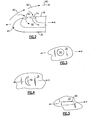
- FIG. 1 With reference to Figure 1 , there is shown a cross-sectional view of a turbine engine assembly 10. Part of turbine engine assembly 10 is nacelle assembly 14. Nacelle assembly 14 has fan cowl 18 and is spaced from core cowl 22 of turbine engine 12 to form bypass flow passage 26. Fan 16 is driven by turbine engine 12 and passes primary thrust through bypass flow passage 26 as known.
- Nacelle assembly 14 is disposed about axis A and has exterior surface 30 and interior surface 34. Exterior surface 30 and interior surface 34 form lip 40. Interior surface 34 further defines air inlet 38 that provides airflow to turbine engine 12 and fan 16.
- nacelle assembly 14 has first opening 58, second opening 62, third opening 70 and fourth opening 74. These openings 58, 62, 70 and 74 are disposed on interior surface 34 of fan cowl 18 as shown and are in fluid communication with flow volume 66. First opening 58 is spaced away from third opening 70 along axis A while second opening 62 is spaced along axis A upstream of fourth opening 74. In addition, first opening 58 is radially spaced from second opening 62 while third opening 70 is radially spaced from fourth opening 74. More or fewer openings can be provided either along axis A or circumferentially around axis A in rows or not in rows.
- Flow volume 66 is further in fluid communication with device for creating suction 46, here a portion of turbine engine 12, having an anticipated lower air pressure than the air pressure around openings 58, 62, 70 and 74.
- Controlling fluid flow from device for creating suction 46 and openings 58, 62, 70and 74 are valves 50. Valves 50 are controlled by control unit 54, which receives data from sensor 56. In addition, fluid flow through openings 58, 62, 70 and 74 are communicated through flow volume 66 and ultimately expelled out nozzle 78 of turbine engine 12. Although fluid flow is shown controlled by control unit 54 and valves 50, adequate suction can be created without the need for such a control.
- airflow 90 here a boundary layer flow, over lip 40 and across interior surface 34.
- control unit 54 opens valve 50, suction is created at openings 58, 62, 70 and 74. Consequently, the low energy flow portion of airflow 90 will be drawn into second opening 62 and fourth opening 74, as shown, and into flow volume 66 and ultimately out nozzle 78. As a consequence of this action, this low energy boundary layer is removed. Airflow 90 will consequently be accelerated around lip 40 and across interior surface 34 of air inlet 38.
- Suction at openings 58, 62, 70 and 74 occurs when control unit 54 through sensor 56 determines that the low energy boundary layer flow of airflow 90 needs to be removed, such that remaining airflow 90 can negotiate flow around lip 40 without major flow separation. Flow separation is likely to occur during static takeoff conditions, a crosswind condition, a climb condition or a windmill condition. During such conditions, control unit 54 controls valve 50 in such a way as to control the rate and level of suction at openings 58, 62, 70 and 74. Otherwise, control unit 54 may determine not to operate valve 50 and not allow for suction at openings 58, 62, 70 and 74, such as when the aircraft is in cruise condition.
- airflow 90 is energized at conditions when airflow about lip 40 and interior surface 34 need be sufficient for turbine engine 12.
- lip 40 and the overall thickness of nacelle assembly 14 may be reduced so as to optimize nacelle assembly 14 for cruise conditions, the majority of the flight conditions for turbine engine 12.
- FIG 3 illustrates opening in the form of a round hole.
- opening may have different shapes.
- fifth opening 82 in the form of a crescent.
- sixth opening 86 in the form of a slot.
- other shapes are also contemplated.
Landscapes
- Engineering & Computer Science (AREA)
- Chemical & Material Sciences (AREA)
- Combustion & Propulsion (AREA)
- Aviation & Aerospace Engineering (AREA)
- Structures Of Non-Positive Displacement Pumps (AREA)
Applications Claiming Priority (1)
| Application Number | Priority Date | Filing Date | Title |
|---|---|---|---|
| US11/956,372 US8192147B2 (en) | 2007-12-14 | 2007-12-14 | Nacelle assembly having inlet bleed |
Publications (2)
| Publication Number | Publication Date |
|---|---|
| EP2072398A2 true EP2072398A2 (de) | 2009-06-24 |
| EP2072398A3 EP2072398A3 (de) | 2012-05-09 |
Family
ID=40336616
Family Applications (1)
| Application Number | Title | Priority Date | Filing Date |
|---|---|---|---|
| EP08253891A Withdrawn EP2072398A3 (de) | 2007-12-14 | 2008-12-05 | Gondelanordnung mit Einlassentlüftung |
Country Status (2)
| Country | Link |
|---|---|
| US (1) | US8192147B2 (de) |
| EP (1) | EP2072398A3 (de) |
Cited By (2)
| Publication number | Priority date | Publication date | Assignee | Title |
|---|---|---|---|---|
| WO2012164187A1 (fr) * | 2011-06-01 | 2012-12-06 | Aircelle | Structure d'entrée d'air de nacelle de turboréacteur |
| EP3034395A1 (de) * | 2014-12-15 | 2016-06-22 | Rolls-Royce Corporation | Flugzeuggrenzschichtentfernung mit hilfstriebwerksansaugen |
Families Citing this family (28)
| Publication number | Priority date | Publication date | Assignee | Title |
|---|---|---|---|---|
| US8572947B2 (en) * | 2008-12-31 | 2013-11-05 | Rolls-Royce Corporation | Gas turbine engine with ejector |
| WO2012018615A1 (en) * | 2010-07-26 | 2012-02-09 | Rolls-Royce Corporation | Gas turbine engine with ejector |
| GB201121887D0 (en) * | 2011-12-20 | 2012-02-01 | Rolls Royce Plc | Intake liner for a gas turbine engine |
| US9932121B2 (en) * | 2012-06-22 | 2018-04-03 | United Technologies Corporation | Turbomachine flow stability enhancement device control |
| US9630706B2 (en) | 2013-02-22 | 2017-04-25 | Rolls-Royce Corporation | Positionable ejector member for ejector enhanced boundary layer alleviation |
| US20160122005A1 (en) | 2013-03-11 | 2016-05-05 | United Technologies Corporation | Embedded engines in hybrid blended wing body |
| US10054048B2 (en) * | 2013-07-26 | 2018-08-21 | Lockheed Martin Corporation | Suprression of shock-induced airflow separation |
| EP3084179B1 (de) | 2013-12-16 | 2020-02-05 | United Technologies Corporation | Bläsergondel mit einströmungsregelung |
| US9758240B2 (en) * | 2014-04-25 | 2017-09-12 | Rohr, Inc. | Modular plenum and duct system for controlling boundary layer airflow |
| US9789954B2 (en) * | 2014-04-25 | 2017-10-17 | Rohr, Inc. | Method of controlling boundary layer flow |
| US10072511B2 (en) | 2014-10-02 | 2018-09-11 | Rolls-Royce North American Technologies Inc. | Engine nacelle |
| EP3090952B1 (de) | 2015-03-31 | 2018-10-03 | Rolls-Royce Corporation | Triebwerksgondel |
| BE1023354B1 (fr) * | 2015-08-13 | 2017-02-13 | Safran Aero Boosters S.A. | Bec de separation degivrant de compresseur de turbomachine axiale |
| US10308368B2 (en) | 2015-10-30 | 2019-06-04 | General Electric Company | Turbofan engine and method of reducing air flow separation therein |
| US10533497B2 (en) * | 2016-04-18 | 2020-01-14 | United Technologies Corporation | Short inlet with integrated liner anti-icing |
| US10605113B2 (en) * | 2017-06-16 | 2020-03-31 | The Boeing Company | Methods and apparatus for reducing flow distortion at engine fans of nacelles |
| FR3075865B1 (fr) * | 2017-12-21 | 2020-07-17 | Safran Nacelles | Ensemble propulsif pour aeronef et procede de ventilation d’une enceinte moteur |
| FR3078744B1 (fr) * | 2018-03-08 | 2020-11-20 | Safran Nacelles | Dispositif actif d’attenuation des emissions acoustiques pour un turboreacteur comportant des turbines controlees |
| US10808572B2 (en) * | 2018-04-02 | 2020-10-20 | General Electric Company | Cooling structure for a turbomachinery component |
| CN112709637B (zh) * | 2019-10-25 | 2022-05-10 | 中国航发商用航空发动机有限责任公司 | 提高航空发动机短舱进气道抗侧风能力的装置和方法 |
| US11828237B2 (en) | 2020-04-28 | 2023-11-28 | General Electric Company | Methods and apparatus to control air flow separation of an engine |
| US11333079B2 (en) * | 2020-04-28 | 2022-05-17 | General Electric Company | Methods and apparatus to detect air flow separation of an engine |
| US11542866B2 (en) * | 2020-05-13 | 2023-01-03 | The Boeing Company | Adaptable flow control for engine nacelles |
| JP7603547B2 (ja) * | 2021-07-26 | 2024-12-20 | 三菱重工業株式会社 | 航空機 |
| CN117818871B (zh) * | 2024-03-04 | 2024-05-17 | 中国空气动力研究与发展中心高速空气动力研究所 | 被动式混合层流短舱应用方法 |
| US12529335B1 (en) | 2024-10-09 | 2026-01-20 | General Electric Company | Turbine engine having a variable engine intake system |
| US12442333B1 (en) | 2024-10-09 | 2025-10-14 | General Electric Company | Turbine engine having a variable engine intake system |
| US12435666B1 (en) | 2024-10-09 | 2025-10-07 | General Electric Company | Turbine engine having a variable engine intake system |
Family Cites Families (125)
| Publication number | Priority date | Publication date | Assignee | Title |
|---|---|---|---|---|
| FR980347A (fr) | 1943-02-05 | 1951-05-10 | Utilisation d'un gradient sciemment établi le long des parois d'un effrps sdlide immergé dans un fluide liquide ou gazeux | |
| US2948111A (en) | 1955-05-02 | 1960-08-09 | Doak Aircraft Co Inc | Means to increase static pressure and enhance forward thrust of aircraft components |
| US2915262A (en) | 1957-09-26 | 1959-12-01 | Douglas Aircraft Co Inc | Vortex inhibitor for aircraft jet engines |
| US3059878A (en) | 1958-11-26 | 1962-10-23 | Rolls Royce | Auxiliary air intakes for jet engines adapted for vertical take-off |
| US3074232A (en) | 1959-07-25 | 1963-01-22 | Soyer Robert | Devices forming the mouthpieces of air admission pipes for jet engines for aircraft |
| US3119581A (en) | 1960-06-18 | 1964-01-28 | Dunlop Rubber Co | Securing means for inflatable inlet device |
| US3222863A (en) | 1963-10-07 | 1965-12-14 | Boeing Co | Aerodynamic inlet |
| GB1070458A (en) | 1964-06-12 | 1967-06-01 | Boeing Co | Separator for removing foreign matter from a gas stream |
| US3298637A (en) | 1964-06-15 | 1967-01-17 | Lee Shao-Tang | Engine inlet protective screen arrangement |
| GB1111219A (en) | 1966-02-14 | 1968-04-24 | Rolls Royce | Gas turbine engine |
| GB1190774A (en) | 1967-04-05 | 1970-05-06 | Rolls Royce | Improvements relating to the Silencing of Gas Turbine Engines |
| US3568694A (en) | 1968-05-08 | 1971-03-09 | Lockheed Aircraft Corp | Jet engine installation for noise control |
| US3524611A (en) | 1968-07-22 | 1970-08-18 | Kurt Frank | Controllable air duct for vertical and short take-off and landing type of air vehicle |
| FR1589899A (de) | 1968-10-24 | 1970-04-06 | ||
| US3541794A (en) | 1969-04-23 | 1970-11-24 | Gen Electric | Bifurcated fan duct thrust reverser |
| GB1252193A (de) | 1969-09-26 | 1971-11-03 | ||
| GB1312619A (en) | 1969-10-03 | 1973-04-04 | Secr Defence | Air intakes for gas turbine engines |
| US3583417A (en) | 1969-10-07 | 1971-06-08 | Boeing Co | Sound suppressor for jet engine inlet |
| US3664612A (en) | 1969-12-22 | 1972-05-23 | Boeing Co | Aircraft engine variable highlight inlet |
| US3611724A (en) | 1970-01-07 | 1971-10-12 | Gen Electric | Choked inlet noise suppression device for a turbofan engine |
| GB1244292A (en) | 1970-01-14 | 1971-08-25 | Rolls Royce | Gas turbine engine |
| US3575259A (en) | 1970-04-10 | 1971-04-20 | Boeing Co | Retractable noise suppression system |
| US3618699A (en) | 1970-04-27 | 1971-11-09 | Gen Electric | Multiple pure tone noise suppression device for an aircraft gas turbine engine |
| GB1336724A (en) | 1970-11-03 | 1973-11-07 | Secr Defence | Gas turbine engine air intakes |
| US3699682A (en) | 1971-01-04 | 1972-10-24 | Mc Donnell Douglas Corp | Turbofan engine thrust reverser |
| US3736750A (en) | 1971-03-12 | 1973-06-05 | Rolls Royce | Power plant |
| GB1382809A (en) | 1971-12-04 | 1975-02-05 | Rolls Royce | Air intakes for gas turbine engines |
| US3770228A (en) | 1971-12-08 | 1973-11-06 | Lockheed Aircraft Corp | Air inlet flap |
| US3905566A (en) | 1972-08-29 | 1975-09-16 | Edwin R Anderson | Jet engine intake protection system |
| US4007891A (en) | 1975-09-12 | 1977-02-15 | The United States Of America As Represented By The Administrator Of The National Aeronautics And Space Administration | Jet engine air intake system |
| US4044973A (en) | 1975-12-29 | 1977-08-30 | The Boeing Company | Nacelle assembly and mounting structures for a turbofan jet propulsion engine |
| US4147029A (en) | 1976-01-02 | 1979-04-03 | General Electric Company | Long duct mixed flow gas turbine engine |
| US4012013A (en) | 1976-02-05 | 1977-03-15 | The Boeing Company | Variable camber inlet for supersonic aircraft |
| US4083181A (en) | 1976-06-14 | 1978-04-11 | The United States Of America As Represented By The Administrator Of The National Aeronautics And Space Administration | Gas turbine engine with recirculating bleed |
| FR2370171A1 (fr) | 1976-11-05 | 1978-06-02 | Snecma | Procede et dispositif pour la diminution du bruit des turbomachines |
| US4132240A (en) | 1977-03-28 | 1979-01-02 | General Electric Company | Variable double lip quiet inlet |
| US4154256A (en) | 1978-03-29 | 1979-05-15 | The United States Of America As Represented By The Administrator Of The National Aeronautics And Space Administration | Self stabilizing sonic inlet |
| US4220171A (en) | 1979-05-14 | 1980-09-02 | The United States Of America As Represented By The Administrator Of The National Aeronautics And Space Administration | Curved centerline air intake for a gas turbine engine |
| US4475702A (en) | 1982-12-28 | 1984-10-09 | The Boeing Company | Variable camber leading edge assembly for an airfoil |
| US4540143A (en) | 1983-08-04 | 1985-09-10 | The Boeing Company | Nacelle/wing assembly with wake control device |
| US4722357A (en) | 1986-04-11 | 1988-02-02 | United Technologies Corporation | Gas turbine engine nacelle |
| US4738416A (en) | 1986-09-26 | 1988-04-19 | Quiet Nacelle Corporation | Nacelle anti-icing system |
| DE3720318A1 (de) | 1987-06-19 | 1989-01-05 | Mtu Muenchen Gmbh | Gondel fuer strahltriebwerke |
| US4912921A (en) | 1988-03-14 | 1990-04-03 | Sundstrand Corporation | Low speed spool emergency power extraction system |
| US4899958A (en) | 1988-12-05 | 1990-02-13 | Mitsubishi Jukogyo Kabushiki Kaisha | Air intake system of an aircraft |
| US5127222A (en) | 1989-01-23 | 1992-07-07 | United Technologies Corporation | Buffer region for the nacelle of a gas turbine engine |
| US5012639A (en) | 1989-01-23 | 1991-05-07 | United Technologies Corporation | Buffer region for the nacelle of a gas turbine engine |
| US5014933A (en) | 1989-04-27 | 1991-05-14 | The Boeing Company | Translating lip aircraft cowling structure adapted for noise reduction |
| US4993663A (en) | 1989-06-01 | 1991-02-19 | General Electric Company | Hybrid laminar flow nacelle |
| US5000399A (en) | 1990-02-23 | 1991-03-19 | General Electric Company | Variable contour annular air inlet for an aircraft engine nacelle |
| DE4009223A1 (de) | 1990-03-22 | 1991-09-26 | Mtu Muenchen Gmbh | Propfan-turbotriebwerk |
| US5143329A (en) | 1990-06-01 | 1992-09-01 | General Electric Company | Gas turbine engine powered aircraft environmental control system and boundary layer bleed |
| US5141182A (en) | 1990-06-01 | 1992-08-25 | General Electric Company | Gas turbine engine fan duct base pressure drag reduction |
| US5058617A (en) | 1990-07-23 | 1991-10-22 | General Electric Company | Nacelle inlet for an aircraft gas turbine engine |
| GB9025023D0 (en) | 1990-11-16 | 1991-01-02 | Rolls Royce Plc | Engine nacelle |
| US5284012A (en) | 1991-05-16 | 1994-02-08 | General Electric Company | Nacelle cooling and ventilation system |
| US5156362A (en) | 1991-05-31 | 1992-10-20 | General Electric Company | Jet engine fan nacelle |
| DE4134051C2 (de) | 1991-10-15 | 1995-02-02 | Mtu Muenchen Gmbh | Turbinenstrahltriebwerk mit Gebläse |
| US5297765A (en) | 1992-11-02 | 1994-03-29 | Rohr, Inc. | Turbine engine nacelle laminar flow control arrangement |
| US5261227A (en) | 1992-11-24 | 1993-11-16 | General Electric Company | Variable specific thrust turbofan engine |
| US5361828A (en) | 1993-02-17 | 1994-11-08 | General Electric Company | Scaled heat transfer surface with protruding ramp surface turbulators |
| US5357742A (en) | 1993-03-12 | 1994-10-25 | General Electric Company | Turbojet cooling system |
| US5447283A (en) | 1994-02-02 | 1995-09-05 | Grumman Aerospace Corporation | Blown boundary layer control system for a jet aircraft |
| DE4426351B4 (de) | 1994-07-25 | 2006-04-06 | Alstom | Brennkammer für eine Gasturbine |
| CA2200053C (en) | 1994-10-13 | 2005-02-22 | The Boeing Company | Jet engine fan noise reduction system utilizing electro-pneumatic transducers |
| GB9424495D0 (en) | 1994-12-05 | 1995-01-25 | Short Brothers Plc | Aerodynamic low drag structure |
| US5586431A (en) | 1994-12-06 | 1996-12-24 | United Technologies Corporation | Aircraft nacelle ventilation and engine exhaust nozzle cooling |
| US5593112A (en) | 1994-12-06 | 1997-01-14 | United Technologies Corporation | Nacelle air pump for vector nozzles for aircraft |
| FR2730763B1 (fr) | 1995-02-21 | 1997-03-14 | Hispano Suiza Sa | Inverseur de poussee a volets aval pour turboreacteur |
| FR2736682B1 (fr) | 1995-07-12 | 1997-08-14 | Hispano Suiza Sa | Inverseur de poussee de turbomachine a double flux a portes dissymetriques |
| US5803410A (en) | 1995-12-01 | 1998-09-08 | The United States Of America As Represented By The Administrator Of The National Aeronautics And Space Administration | Skin friction reduction by micro-blowing technique |
| US5813625A (en) | 1996-10-09 | 1998-09-29 | Mcdonnell Douglas Helicopter Company | Active blowing system for rotorcraft vortex interaction noise reduction |
| US5987880A (en) | 1997-07-08 | 1999-11-23 | Mcdonnell Douglas Corporation | Supersonic engine, multi-port thrust reversing system |
| US6089505A (en) | 1997-07-22 | 2000-07-18 | Mcdonnell Douglas Corporation | Mission adaptive inlet |
| US6129311A (en) | 1997-07-30 | 2000-10-10 | The Boeing Company | Engine nacelle outer cowl panel with integral track fairings |
| US6055805A (en) | 1997-08-29 | 2000-05-02 | United Technologies Corporation | Active rotor stage vibration control |
| US5934611A (en) | 1997-10-20 | 1999-08-10 | Northrop Grumman Corporation | Low drag inlet design using injected duct flow |
| GB9723022D0 (en) | 1997-11-01 | 1998-01-07 | Rolls Royce Plc | Gas turbine apparatus |
| US5841079A (en) | 1997-11-03 | 1998-11-24 | Northrop Grumman Corporation | Combined acoustic and anti-ice engine inlet liner |
| US5971328A (en) | 1998-01-15 | 1999-10-26 | Kota; Sridhar | System for varying a surface contour |
| US6179251B1 (en) | 1998-02-06 | 2001-01-30 | Northrop Grumman Corporation | Thin inlet lip design for low drag and reduced nacelle size |
| US6129309A (en) | 1998-07-24 | 2000-10-10 | Mcdonnell Douglas Corporation | Aircraft engine apparatus with reduced inlet vortex |
| US6379110B1 (en) | 1999-02-25 | 2002-04-30 | United Technologies Corporation | Passively driven acoustic jet controlling boundary layers |
| US6109566A (en) | 1999-02-25 | 2000-08-29 | United Technologies Corporation | Vibration-driven acoustic jet controlling boundary layer separation |
| US6390418B1 (en) | 1999-02-25 | 2002-05-21 | United Technologies Corporation | Tangentially directed acoustic jet controlling boundary layer |
| GB9921935D0 (en) | 1999-09-17 | 1999-11-17 | Rolls Royce | A nacelle assembly for a gas turbine engine |
| US6259976B1 (en) | 1999-09-25 | 2001-07-10 | Jerome H. Lemelson | Fuzzy logic based emergency flight control with thrust vectoring |
| US6334612B1 (en) * | 1999-11-17 | 2002-01-01 | Wms Gaming Inc. | Ergonomically-designed gaming machine |
| US6340135B1 (en) | 2000-05-30 | 2002-01-22 | Rohr, Inc. | Translating independently mounted air inlet system for aircraft turbofan jet engine |
| US6334753B1 (en) | 2000-07-31 | 2002-01-01 | United Technologies Corporation | Streamlined bodies with counter-flow fluid injection |
| US6375118B1 (en) | 2000-08-30 | 2002-04-23 | The Boeing Company | High frequency excitation apparatus and method for reducing jet and cavity noise |
| US7048229B2 (en) | 2000-09-26 | 2006-05-23 | Techland Research, Inc. | Low sonic boom inlet for supersonic aircraft |
| DE10059212A1 (de) * | 2000-11-29 | 2002-06-13 | Grohe Armaturen Friedrich | Brausehaltevorrichtung |
| US6471477B2 (en) | 2000-12-22 | 2002-10-29 | The Boeing Company | Jet actuators for aerodynamic surfaces |
| FR2820716B1 (fr) | 2001-02-15 | 2003-05-30 | Eads Airbus Sa | Procede de degivrage par circulation forcee d'un fluide, d'un capot d'entree d'air de moteur a reaction et dispositif pour sa mise en oeuvre |
| US6651929B2 (en) | 2001-10-29 | 2003-11-25 | Pratt & Whitney Canada Corp. | Passive cooling system for auxiliary power unit installation |
| FR2831922B1 (fr) | 2001-11-02 | 2004-04-30 | Airbus France | Entree d'air pour nacelle de moteur a reaction d'avion commercial |
| DE10330023A1 (de) | 2002-07-20 | 2004-02-05 | Alstom (Switzerland) Ltd. | Wirbelgenerator mit kontrollierter Nachlaufströmung |
| US6655632B1 (en) | 2002-08-27 | 2003-12-02 | General Electric Company | System and method for actively changing an effective flow-through area of an inlet region of an aircraft engine |
| US6763651B2 (en) | 2002-10-25 | 2004-07-20 | The Boeing Company | Active system for wide area suppression of engine vortex |
| US6793177B2 (en) | 2002-11-04 | 2004-09-21 | The Bonutti 2003 Trust-A | Active drag and thrust modulation system and method |
| US6764043B2 (en) | 2002-12-11 | 2004-07-20 | The Boeing Company | Rotatable scarf inlet for an aircraft engine and method of using the same |
| US6971229B2 (en) | 2003-02-26 | 2005-12-06 | The Nordam Group, Inc. | Confluent exhaust nozzle |
| GB2402196B (en) | 2003-05-29 | 2006-05-17 | Rolls Royce Plc | A laminar flow nacelle for an aircraft engine |
| GB0312505D0 (en) | 2003-05-31 | 2003-07-09 | Rolls Royce Plc | Engine nozzle |
| US7090165B2 (en) | 2003-06-02 | 2006-08-15 | Rolls-Royce Plc | Aeroengine nacelle |
| US7131612B2 (en) | 2003-07-29 | 2006-11-07 | Pratt & Whitney Canada Corp. | Nacelle inlet lip anti-icing with engine oil |
| US7631483B2 (en) | 2003-09-22 | 2009-12-15 | General Electric Company | Method and system for reduction of jet engine noise |
| GB2407142B (en) * | 2003-10-15 | 2006-03-01 | Rolls Royce Plc | An arrangement for bleeding the boundary layer from an aircraft engine |
| GB0401189D0 (en) | 2004-01-21 | 2004-02-25 | Rolls Royce Plc | Turbine engine arrangements |
| DE102004024007B4 (de) | 2004-05-13 | 2007-10-11 | Airbus Deutschland Gmbh | Flugzeugkomponente, insbesondere Flügel |
| US20050274103A1 (en) | 2004-06-10 | 2005-12-15 | United Technologies Corporation | Gas turbine engine inlet with noise reduction features |
| US7255309B2 (en) | 2004-07-14 | 2007-08-14 | The Boeing Company | Vernier active flow control effector |
| GB0418196D0 (en) | 2004-08-14 | 2004-09-15 | Rolls Royce Plc | Boundary layer control arrangement |
| US20060155432A1 (en) | 2005-01-07 | 2006-07-13 | United Technologies Corporation | Methods and systems for monitoring atmospheric conditions, predicting turbulent atmospheric conditions and optimizing flight paths of aircraft |
| US7617670B2 (en) | 2006-03-31 | 2009-11-17 | Lockheed Martin Corporation | Flow control redistribution to mitigate high cycle fatigue |
| US7797944B2 (en) | 2006-10-20 | 2010-09-21 | United Technologies Corporation | Gas turbine engine having slim-line nacelle |
| US7870721B2 (en) | 2006-11-10 | 2011-01-18 | United Technologies Corporation | Gas turbine engine providing simulated boundary layer thickness increase |
| US8408491B2 (en) | 2007-04-24 | 2013-04-02 | United Technologies Corporation | Nacelle assembly having inlet airfoil for a gas turbine engine |
| US8205430B2 (en) | 2007-05-16 | 2012-06-26 | United Technologies Corporation | Variable geometry nacelle assembly for a gas turbine engine |
| US8727267B2 (en) | 2007-05-18 | 2014-05-20 | United Technologies Corporation | Variable contraction ratio nacelle assembly for a gas turbine engine |
| US7766280B2 (en) | 2007-05-29 | 2010-08-03 | United Technologies Corporation | Integral suction device with acoustic panel |
| US8402739B2 (en) | 2007-06-28 | 2013-03-26 | United Technologies Corporation | Variable shape inlet section for a nacelle assembly of a gas turbine engine |
| US9228534B2 (en) | 2007-07-02 | 2016-01-05 | United Technologies Corporation | Variable contour nacelle assembly for a gas turbine engine |
| US9004399B2 (en) * | 2007-11-13 | 2015-04-14 | United Technologies Corporation | Nacelle flow assembly |
-
2007
- 2007-12-14 US US11/956,372 patent/US8192147B2/en active Active
-
2008
- 2008-12-05 EP EP08253891A patent/EP2072398A3/de not_active Withdrawn
Cited By (5)
| Publication number | Priority date | Publication date | Assignee | Title |
|---|---|---|---|---|
| WO2012164187A1 (fr) * | 2011-06-01 | 2012-12-06 | Aircelle | Structure d'entrée d'air de nacelle de turboréacteur |
| FR2975972A1 (fr) * | 2011-06-01 | 2012-12-07 | Aircelle Sa | Structure d'entree d'air de nacelle de turboreacteur |
| CN103562068A (zh) * | 2011-06-01 | 2014-02-05 | 埃尔塞乐公司 | 用于涡轮喷气发动机舱的进气口结构 |
| CN103562068B (zh) * | 2011-06-01 | 2016-03-30 | 埃尔塞乐公司 | 用于涡轮喷气发动机舱的进气口结构 |
| EP3034395A1 (de) * | 2014-12-15 | 2016-06-22 | Rolls-Royce Corporation | Flugzeuggrenzschichtentfernung mit hilfstriebwerksansaugen |
Also Published As
| Publication number | Publication date |
|---|---|
| EP2072398A3 (de) | 2012-05-09 |
| US20090155046A1 (en) | 2009-06-18 |
| US8192147B2 (en) | 2012-06-05 |
Similar Documents
| Publication | Publication Date | Title |
|---|---|---|
| US8192147B2 (en) | Nacelle assembly having inlet bleed | |
| EP2060489B1 (de) | Gondelströmungsanordnung | |
| US8186942B2 (en) | Nacelle assembly with turbulators | |
| EP1921291B1 (de) | Gasturbinenmotor mit simulierter Grenzschichtverdickung | |
| EP1998027B1 (de) | Gasturbine mit einem Plenum innerhalb einer Triebwerksgondel und einem Zapfluftsystem | |
| EP1998029B1 (de) | System zur Steuerung der Einlassströmung für eine Gondel, zugehörige Gondelanordnung und Verfahren zur Steuerung einer Strömung | |
| US12123359B2 (en) | Controlling a compressor of a turbine engine | |
| EP3284942B1 (de) | Fantriebwerk mit hinten angeordneten und direkt angetriebenen fan | |
| CN109083690B (zh) | 具有可变有效喉道的涡轮发动机 | |
| EP2982833B1 (de) | Gasturbinenmotor | |
| EP2472085A2 (de) | Gasturbinenmotor mit Entlüftungsstelle | |
| EP2074323B1 (de) | Turbofantriebwerk mit variablem bypassdüsenauslassbereich und betriebsverfahren | |
| EP2074318B1 (de) | Mantelstromtriebwerk und Verfahren zur Änderung des Austrittsquerschnitts einer Mantelstromdüse | |
| EP3428436B1 (de) | Flugzeug mit einem schubrückgewinnungssystem mit verwendung von kabinenluft | |
| EP3966443B1 (de) | Umkehrbare ablassvorrichtung | |
| US20160003091A1 (en) | Nacelle internal and external flow control | |
| US20100089030A1 (en) | Controlling the aerodynamic drag of a gas turbine engine during a shutdown state |
Legal Events
| Date | Code | Title | Description |
|---|---|---|---|
| PUAI | Public reference made under article 153(3) epc to a published international application that has entered the european phase |
Free format text: ORIGINAL CODE: 0009012 |
|
| AK | Designated contracting states |
Kind code of ref document: A2 Designated state(s): AT BE BG CH CY CZ DE DK EE ES FI FR GB GR HR HU IE IS IT LI LT LU LV MC MT NL NO PL PT RO SE SI SK TR |
|
| AX | Request for extension of the european patent |
Extension state: AL BA MK RS |
|
| PUAL | Search report despatched |
Free format text: ORIGINAL CODE: 0009013 |
|
| AK | Designated contracting states |
Kind code of ref document: A3 Designated state(s): AT BE BG CH CY CZ DE DK EE ES FI FR GB GR HR HU IE IS IT LI LT LU LV MC MT NL NO PL PT RO SE SI SK TR |
|
| AX | Request for extension of the european patent |
Extension state: AL BA MK RS |
|
| RIC1 | Information provided on ipc code assigned before grant |
Ipc: B64D 33/02 20060101AFI20120403BHEP |
|
| AKY | No designation fees paid | ||
| REG | Reference to a national code |
Ref country code: DE Ref legal event code: R108 |
|
| REG | Reference to a national code |
Ref country code: DE Ref legal event code: R108 Effective date: 20130116 |
|
| STAA | Information on the status of an ep patent application or granted ep patent |
Free format text: STATUS: THE APPLICATION IS DEEMED TO BE WITHDRAWN |
|
| 18D | Application deemed to be withdrawn |
Effective date: 20121110 |