EP2072640A2 - Geteilte elektrochemische Zelle und Herstellungsverfahren von hochreinem Metallhydridgas - Google Patents
Geteilte elektrochemische Zelle und Herstellungsverfahren von hochreinem Metallhydridgas Download PDFInfo
- Publication number
- EP2072640A2 EP2072640A2 EP08171783A EP08171783A EP2072640A2 EP 2072640 A2 EP2072640 A2 EP 2072640A2 EP 08171783 A EP08171783 A EP 08171783A EP 08171783 A EP08171783 A EP 08171783A EP 2072640 A2 EP2072640 A2 EP 2072640A2
- Authority
- EP
- European Patent Office
- Prior art keywords
- anode
- cathode
- metal
- chamber
- gas
- Prior art date
- Legal status (The legal status is an assumption and is not a legal conclusion. Google has not performed a legal analysis and makes no representation as to the accuracy of the status listed.)
- Granted
Links
Images






Classifications
-
- C—CHEMISTRY; METALLURGY
- C25—ELECTROLYTIC OR ELECTROPHORETIC PROCESSES; APPARATUS THEREFOR
- C25B—ELECTROLYTIC OR ELECTROPHORETIC PROCESSES FOR THE PRODUCTION OF COMPOUNDS OR NON-METALS; APPARATUS THEREFOR
- C25B15/00—Operating or servicing cells
- C25B15/02—Process control or regulation
-
- C—CHEMISTRY; METALLURGY
- C25—ELECTROLYTIC OR ELECTROPHORETIC PROCESSES; APPARATUS THEREFOR
- C25B—ELECTROLYTIC OR ELECTROPHORETIC PROCESSES FOR THE PRODUCTION OF COMPOUNDS OR NON-METALS; APPARATUS THEREFOR
- C25B1/00—Electrolytic production of inorganic compounds or non-metals
- C25B1/01—Products
- C25B1/02—Hydrogen or oxygen
- C25B1/04—Hydrogen or oxygen by electrolysis of water
-
- C—CHEMISTRY; METALLURGY
- C23—COATING METALLIC MATERIAL; COATING MATERIAL WITH METALLIC MATERIAL; CHEMICAL SURFACE TREATMENT; DIFFUSION TREATMENT OF METALLIC MATERIAL; COATING BY VACUUM EVAPORATION, BY SPUTTERING, BY ION IMPLANTATION OR BY CHEMICAL VAPOUR DEPOSITION, IN GENERAL; INHIBITING CORROSION OF METALLIC MATERIAL OR INCRUSTATION IN GENERAL
- C23C—COATING METALLIC MATERIAL; COATING MATERIAL WITH METALLIC MATERIAL; SURFACE TREATMENT OF METALLIC MATERIAL BY DIFFUSION INTO THE SURFACE, BY CHEMICAL CONVERSION OR SUBSTITUTION; COATING BY VACUUM EVAPORATION, BY SPUTTERING, BY ION IMPLANTATION OR BY CHEMICAL VAPOUR DEPOSITION, IN GENERAL
- C23C16/00—Chemical coating by decomposition of gaseous compounds, without leaving reaction products of surface material in the coating, i.e. chemical vapour deposition [CVD] processes
- C23C16/44—Chemical coating by decomposition of gaseous compounds, without leaving reaction products of surface material in the coating, i.e. chemical vapour deposition [CVD] processes characterised by the method of coating
- C23C16/448—Chemical coating by decomposition of gaseous compounds, without leaving reaction products of surface material in the coating, i.e. chemical vapour deposition [CVD] processes characterised by the method of coating characterised by the method used for generating reactive gas streams, e.g. by evaporation or sublimation of precursor materials
- C23C16/4488—Chemical coating by decomposition of gaseous compounds, without leaving reaction products of surface material in the coating, i.e. chemical vapour deposition [CVD] processes characterised by the method of coating characterised by the method used for generating reactive gas streams, e.g. by evaporation or sublimation of precursor materials by in situ generation of reactive gas by chemical or electrochemical reaction
-
- C—CHEMISTRY; METALLURGY
- C25—ELECTROLYTIC OR ELECTROPHORETIC PROCESSES; APPARATUS THEREFOR
- C25B—ELECTROLYTIC OR ELECTROPHORETIC PROCESSES FOR THE PRODUCTION OF COMPOUNDS OR NON-METALS; APPARATUS THEREFOR
- C25B1/00—Electrolytic production of inorganic compounds or non-metals
-
- C—CHEMISTRY; METALLURGY
- C25—ELECTROLYTIC OR ELECTROPHORETIC PROCESSES; APPARATUS THEREFOR
- C25B—ELECTROLYTIC OR ELECTROPHORETIC PROCESSES FOR THE PRODUCTION OF COMPOUNDS OR NON-METALS; APPARATUS THEREFOR
- C25B1/00—Electrolytic production of inorganic compounds or non-metals
- C25B1/01—Products
-
- C—CHEMISTRY; METALLURGY
- C25—ELECTROLYTIC OR ELECTROPHORETIC PROCESSES; APPARATUS THEREFOR
- C25B—ELECTROLYTIC OR ELECTROPHORETIC PROCESSES FOR THE PRODUCTION OF COMPOUNDS OR NON-METALS; APPARATUS THEREFOR
- C25B1/00—Electrolytic production of inorganic compounds or non-metals
- C25B1/01—Products
- C25B1/23—Carbon monoxide or syngas
-
- C—CHEMISTRY; METALLURGY
- C25—ELECTROLYTIC OR ELECTROPHORETIC PROCESSES; APPARATUS THEREFOR
- C25B—ELECTROLYTIC OR ELECTROPHORETIC PROCESSES FOR THE PRODUCTION OF COMPOUNDS OR NON-METALS; APPARATUS THEREFOR
- C25B15/00—Operating or servicing cells
- C25B15/02—Process control or regulation
- C25B15/023—Measuring, analysing or testing during electrolytic production
- C25B15/025—Measuring, analysing or testing during electrolytic production of electrolyte parameters
-
- C—CHEMISTRY; METALLURGY
- C25—ELECTROLYTIC OR ELECTROPHORETIC PROCESSES; APPARATUS THEREFOR
- C25B—ELECTROLYTIC OR ELECTROPHORETIC PROCESSES FOR THE PRODUCTION OF COMPOUNDS OR NON-METALS; APPARATUS THEREFOR
- C25B9/00—Cells or assemblies of cells; Constructional parts of cells; Assemblies of constructional parts, e.g. electrode-diaphragm assemblies; Process-related cell features
- C25B9/17—Cells comprising dimensionally-stable non-movable electrodes; Assemblies of constructional parts thereof
- C25B9/19—Cells comprising dimensionally-stable non-movable electrodes; Assemblies of constructional parts thereof with diaphragms
-
- C—CHEMISTRY; METALLURGY
- C25—ELECTROLYTIC OR ELECTROPHORETIC PROCESSES; APPARATUS THEREFOR
- C25B—ELECTROLYTIC OR ELECTROPHORETIC PROCESSES FOR THE PRODUCTION OF COMPOUNDS OR NON-METALS; APPARATUS THEREFOR
- C25B9/00—Cells or assemblies of cells; Constructional parts of cells; Assemblies of constructional parts, e.g. electrode-diaphragm assemblies; Process-related cell features
- C25B9/40—Cells or assemblies of cells comprising electrodes made of particles; Assemblies of constructional parts thereof
-
- Y—GENERAL TAGGING OF NEW TECHNOLOGICAL DEVELOPMENTS; GENERAL TAGGING OF CROSS-SECTIONAL TECHNOLOGIES SPANNING OVER SEVERAL SECTIONS OF THE IPC; TECHNICAL SUBJECTS COVERED BY FORMER USPC CROSS-REFERENCE ART COLLECTIONS [XRACs] AND DIGESTS
- Y02—TECHNOLOGIES OR APPLICATIONS FOR MITIGATION OR ADAPTATION AGAINST CLIMATE CHANGE
- Y02E—REDUCTION OF GREENHOUSE GAS [GHG] EMISSIONS, RELATED TO ENERGY GENERATION, TRANSMISSION OR DISTRIBUTION
- Y02E60/00—Enabling technologies; Technologies with a potential or indirect contribution to GHG emissions mitigation
- Y02E60/30—Hydrogen technology
- Y02E60/36—Hydrogen production from non-carbon containing sources, e.g. by water electrolysis
Definitions
- This invention is in the field of electrochemical processes and apparatus. More specifically, the present invention is directed to the divided electrochemical cell synthesis and production of Group IV and V volatile hydrides with the simultaneous counter production of oxygen, and a reactor for carrying out the synthesis.
- the synthesis and the reactor are designed to more efficiently produce high purity hydrides substantially free of oxygen.
- Porter in U.S. Pat. No. 4,178,224 , discloses an electrochemical method for the synthesis of arsine gas that utilizes a dissolved arsenic salt in an acidic electrolyte with an oxygen evolving anode. With this method, however, the arsine concentration was limited to less than 25%. Another limitation of Porter's method was the need to balance pressures and liquid levels in the divided anode and cathode sections of the electrochemical cell. This requires an inert gas supply to the electrochemical process.
- Bouard in U.S. Pat. No. 5,425,857 , discloses an electrochemical process utilizing an electrolyte containing arsenic salts and acid which operates in a divided electrochemical, generating arsine and hydrogen in the cathode chamber, and oxygen in the anode chamber.
- the process in burdened by the need to use auxiliary gas separation tanks and multiple pumps.
- the simultaneous metering and addition of both acid and arsenic salt is required to maintain the process.
- a first embodiment of the invention includes an apparatus for generating a hydride gas of metal M 1 comprising :
- Another embodiment of the invention includes a method for generating a hydride gas of metal M 1 in a divided electrochemical cell comprising (a) tubular housing wherein at least part of the tubular housing comprising metal M 2 ; (b) an electrical insulator bottom; (c) an electrical insulator top lid comprising a cathode gas outlet, an anode gas outlet and a water inlet; (d) a divider that divides the divided electrochemical cell into a cathode chamber and an anode chamber, wherein the divider is electrically insulated from anode and cathode circuits; (e) the cathode chamber comprising a cathode selected from the group consisting of a solid rod of metal M 1 and a fixed bed of metal M 1 granules, and the cathode gas outlet; and (f) the anode chamber comprising an anode that is the at least part of tubular housing comprising metal M 2 , the anode gas outlet and the water inlet; the method comprising
- an apparatus for generating a hydride gas of arsenic metal comprising:
- another embodiment of the invention includes a method for generating a hydride gas of arsenic metal in a divided electrochemical cell comprising (a) tubular housing wherein at least part of the tubular housing comprising metal nickel; (b) an electrical insulator bottom; (c) an electrical insulator top lid comprising a cathode gas outlet, an anode gas outlet and a water inlet; (d) a divider that divides the divided electrochemical cell into a cathode chamber and a anode chamber, wherein the divider is electrically insulated from anode and cathode circuits; (e) the cathode chamber comprising a cathode selected from the group consisting of a solid rod As and a fixed bed of metal As granules, and the cathode gas outlet; and (f)the anode chamber comprising an anode that is the at least part of tubular housing comprising metal nickel, the anode gas outlet and the water inlet; the method comprising the steps of:
- an apparatus for generating a hydride gas of arsenic metal comprising:
- another embodiment of the invention includes a method for generating a hydride gas of metal M 1 in a divided electrochemical cell comprising (a) a U-shaped tubular housing at least partially comprising metal M 2 ; wherein one side of the U-shaped tubular housing forms a cathode chamber; the other side of the U-shaped tubular housing forms an anode chamber; and bottom part of the U-shaped tubular housing comprises an electrical insulator connecting the cathode chamber and the anode chamber while not allowing mixing of a cathode gas with an anode gas; (b) the cathode chamber comprises a cathode selected from the group consisting of a solid rod of metal M 1 and a fixed bed of metal M 1 granules, and an electrical insulator top lid comprising a cathode gas outlet; (c) the anode chamber comprises an anode that is the other side of the U-shaped tubular housing comprising metal M 2 , and an electrical insulator top lid comprising a ano
- M 1 is a metal or a metal alloy selected from the group consisting of Sb, As, Se, P, Si, Ge, Pb, Cd and combinations thereof;
- M 2 is a metal or a metal alloy suitable for anodic oxygen generation including nickel, copper, stainless steel, and aluminum and combinations thereof;
- M 3 is selected from the group consisting of alkali and alkaline earth metals; and
- M 3 OH in the aqueous electrolyte solution ranges from 2% to 45% by weight of; further, M 3 OH is selected from the group consisting of NaOH, KOH, LiOH, CsOH, NH 4 OH and combinations thereof.
- the divided electrochemical cell operates under a current density ranges from about 100 to about 15,000 A/m 2 ; or a constant voltage V ranges from about 2 to about 15 volts; a temperature ranges about 15°C to about 100°C; Pc and Pa range from about 50,000 to about 500,000 Pa; and ⁇ P ranges from about 1 to about 10,000 Pa; and water is added to the anode chamber continuously or batch-wisely.
- the divider is a solid impermeable partition partially extending into the aqueous electrolyte solution to prevent the mixing of the anode gas with the cathode gas.
- the divider is a combination of a solid impermeable partition and a porous permeable diaphragm wherein porous size in the porous permeable diaphragm is smaller than the gas bubbles generated in the anode chamber and the cathode chamber to prevent mixing of the gas bubbles; and the divider at least partially extends into the aqueous electrolyte solution to prevent mixing of an anode gas with a cathode gas.
- the embodiments above further include a heat transfer jacket covering the tubular housing of the divided electrochemical cell comprising an inlet and an outlet for circulating cooling fluid, to control the temperature of the divided electrochemical cell.
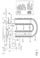
- Figure 1 Divided electrochemical cell with "U-shape" configuration.
- the cathode consists of a solid metal rod made of the hydride metal.
- FIG. 2 Divided electrochemical cell with "U-shape" configuration.
- the cathode consists of a fixed bed of metal granules made of the hydride metal.
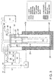
- Figure 3 Divided electrochemical cell with "tube-in-tube” configuration. A solid partition divides the electrochemical cell.
- the cathode consists of a solid metal rod made of the hydride metal.
- Figure 4 Divided electrochemical cell with "tube-in-tube” configuration. A solid partition divides the electrochemical cell.
- the cathode consists of a fixed bed of metal granules made of the hydride metal.
- Figure 5 Divided electrochemical cell with "tube-in-tube” configuration. A solid partition adjoining a porous diaphragm divides the electrochemical cell.
- the cathode consists of a solid metal rod made of the hydride metal.
- Figure 6 Divided electrochemical cell with "tube-in-tube” configuration. A solid partition adjoining a porous diaphragm divides the electrochemical cell.
- the cathode consists of a fixed bed of metal granules made of the hydride metal.
- Figure 7 Typical operating curves for the ASH 3 /O2 divided electrochemical cell.
- Figure 8 Background quadrapole-mass-spectra in helium showing residual species in the analyzer.
- Figure 9 Quadrapole mass spectra of the cathode gas.
- Figure 10 Quadrapole mass spectra of the anode gas diluted with nitrogen.
- the present invention discloses apparatuses and methods to continuously manufacture a high quality and low cost hydride gas that is substantially free of oxygen, for use in the fabrication of electronic and solar cell materials.
- hydride gases are available in bulk high pressure cylinders or adsorbed on solid support. Hydride gases are extremely toxic and an alternative to storing them in bulk is to provide insitu production of the hydride gases by electrochemical generation.
- the present invention allows for reduced real time inventory of the hydride gas to a minor fraction of what would be present in any bulk storage system.
- hydride would be present production from the divided electrochemical cell can be instantly shut down by turning off the electrical current in the event of an unexpected safety problem in the facility using the hydride gas.
- Divided electrochemical cells prefitted with metal cathodes can be shipped (without hydride gas in the cell) and stored at a location for onsite operation without the concern of the hydride gas leaking.
- the current zinc arsenide manufacturing process creates a crude gas that contains sulfur impurities. These must be removed.
- the present invention avoids these impurities.
- the new process must be operated in a manner to avoid oxygen contamination of the arsine gas.
- the insitu electrochemical generation of hydrides from their corresponding metal cathodes has been developed.
- the anode is a sacrificial metal, such as molybdenum, cadmium, or tungsten, which is expensive and generates a salt waste.
- the present invention only water and the metal cathode are consumed and the expensive sacrificial anode is avoided.
- the apparatus comprises a divided electrochemical cell where a solid arsenic rod serves as a cathode and a nickel tube serves as the anode.
- the electrolyte is any aqueous hydroxide salt, for example, 20 to 25% aqueous solution of potassium hydroxide.
- the electrochemical cell is divided into an anode chamber a cathode chamber so that the oxygen and arsine gases do not mix.
- the gases exist via independent outlets in the gas phase of their respective chambers.
- One option uses a solid partition and the other option uses a solid partition in combination with a porous diaphragm.
- An optional cylindrical divided electrochemical cell design allows the process to efficiently operate at pressures higher than atmospheric facilitating the removal of impurities such as water and feeding to auxiliary equipment processing the hydride gas.
- the method of operation comprises the steps of maintaining the liquid levels to ensure that the metal hydride gas and oxygen do not mix; continuously removing the hydride gas from the cathode chamber and oxygen from the anode chamber; continually replacing water as it is consumed; controlling the liquid level to ensure that a hydraulic seal is maintained; controlling the electrical current supplied to the divided electrochemical cell to ensure that the vessel is not over pressurized; controlling the hydride stream purity so that it is substantially free of oxygen.
- FIGS 1 to 6 illustrate variations of the divided electrochemical cell designs with separate anode chamber and cathode chamber.
- Figures 1 and 2 show divided electrochemical cells designed with a U-shaped tubular housing configuration where an electrically insulated conduit bottom part 29 connects the anode chamber 26 and a cathode chamber 25.
- the conduit is located sufficiently low so that it serves to partition the gases evolved at the anode chamber and the cathode chamber do not mix but rise via buoyancy forces into the gas "head-space" regions of their respective chambers (the top portions of chambers 26 and 25 ).
- the gases are allowed to exit out of these "head-space” regions through gas outlets 40 and 41.
- Make-up water can be added continuously or batch-wise via inlet 45. Continuous liquid communication between the anode chamber and cathode chamber is necessary to allow the flow of ions between the chambers, however, the openings which allow this communication should be provided so that rising bubbles of oxygen and arsine do not recombine.
- the anode chamber and cathode chamber are arranged in the form of a "tube in a tube" configuration, wherein the anode chamber is annular geometry around a central tubular cathode chamber.
- the particular layout is governed by materials' availability or manufacturing preference for different size of divided electrochemical cells.
- Figures 3 and 4 show divided electrochemical cells with a "tube in a tube” structure designed with a solid partition: a solid, impermeable partition 20 divides the electrochemical cell into an anode chamber 26 and a cathode chamber 25.
- the partition 20 extends into the aqueous electrolyte sufficiently so that gases evolved at the anode chamber and the cathode chamber do not mix but rise via buoyancy forces into the gas "head-space" regions of their respective chambers (the top portions of chambers 26 and 25 ).
- the gases are allowed to exit out of these "head-space” regions through gas outlets 40 and 41.
- Make-up water can be added continuously or batch-wise via inlet 45. Continuous liquid communication between the anode chamber and cathode chamber is necessary to allow the flow of ions between the chambers, however, the openings which allow this communication should be provided so that rising bubbles of oxygen and arsine do not recombine.
- Figures 5 and 6 show divided electrochemical cells with a "tube in a tube” structure designed with a combined solid partition 20 and porous/permeable diaphragm 21: the combined partitions 20 and 21 divide the electrochemical cell into an anode chamber 26 and a cathode chamber 25.
- the partition 20 extends into the aqueous electrolyte where it adjoins to a porous/liquid permeable diaphragm 21.
- the holes in the diaphragm are sufficiently small that oxygen and arsine gas bubbles cannot pass through the diaphragm.
- This diaphragm may continue to the bottom of the divided electrochemical cell so that the only liquid communication between the anode and cathode chamber is through the holes in the diaphragm.
- Temperature control of the divided electrochemical cell can be achieve through a jacket 27 around the divided electrochemical cell by using a conventional source of cooling fluid (electrically non-conducting fluid) through inlet 23 which exits the jacket through outlet 22.
- cooling fluid electrically non-conducting fluid
- Nickel is an acceptable material of construction for 31 , when aqueous alkali hydroxide electrolytes are used.
- Composite divided electrochemical cell of plastic such as high density polyethylene with a thin nickel electrode is also acceptable.
- a divided electrochemical cell was constructed according to Figure 1 , in a "U-shaped" tube configuration.
- the vertical anode chamber 26 consisted of a 24.5mm ID nickel tube and the vertical cathode chamber 25 consisted of a 24.5mm ID 316 stainless steel tube. The two chambers were connected at the bottom via a 24.5 mm ID Teflon tube.
- the cathode was a 99% purity arsenic rod, 21 mm diameter and 486 mm long weighing 940 g. It was positioned in the stainless steel tube with plastic spacers to insure that the arsenic rod did not contact the stainless steel housing.
- the anode chamber and cathode chamber were filled with 250 ml of a 25% by weight aqueous KOH solution.
- the divided electrochemical cell was not jacketed and ambient external cooling was accomplished with a fan.
- the anode chamber was vented to the atmosphere and the oxygen generated at the anode was blended with nitrogen purge gas.
- the divided electrochemical cell was operated at a constant current A of 3.0 amps or with a current density of 8,700 A/m 2 , while the divided electrochemical cell voltage fluctuated between 10 and 12 volts.
- the current density is defined as the total current at the anode divided by the wetted (immersed in the aqueous KOH solution) anode geometric surface area.
- the differential pressure between the cathode chamber and the anode chamber was maintained between 250 and 1,000 Pa with a control valve on the cathode chamber. Above a differential pressure of 1,000 Pa the cathode gas was released from the divided electrochemical cell into the gas analyzer and collection chamber until the differential pressure reached 250 Pa at which time the control valve was closed. This effect caused the liquid level in the divided electrochemical cell to oscillate during constant current operation.
- the gas composition consisted of essentially 82% to 86% (mole %) arsine with the make-up consisting of hydrogen, 18% to 14%.
- the divided electrochemical cell temperature was maintained between 58°C and 70°C
- Figure 7 shows a typical operating curve for the AsH 3 /O 2 divided electrochemical cell. lndicated are the points at which the anode and cathode gases were analyzed with a quadrapole-mass-spectrometer, QMS. The results are showing in Figures 9 and 10 .
- Figure 8 shows a background quadrapole-mass-spectra in helium showing residual species in the analyzer.
- Figure 9 shows a quadrapole mass spectra of the cathode gas showing essentially pure arsine with a trace of hydrogen. Note that the residual oxygen is the same level as the background in Figure 8 . As the result, the arsenic gas generated in the cathode chamber is not mixed with oxygen gas generated in the anode chamber.
- the generated arsine from a divided electrochemical cell divided into an anode chamber and a cathode chamber by solid partition, as designed in Figures 1 through 6 , is substantially free of oxygen.
- Figure 10 shows a quadrapole mass spectra of the anode gas diluted with nitrogen showing essentially pure oxygen.
- the divided electrochemical cell was operated exactly as in Example 1 however the arsenic rod was replaced with a fixed bed of arsenic granules, 99% purity, with an average particle size of 3 mm.
- the arsenic granular bed was 1" tall and made electrical contact with the stainless steel tubular housing.
- the negative electrode from the power supply was attached to the outer wall of the stainless steel cathode housing and made electrical connection was made to the arsenic bed.
- the arsine gas was approximately 85% with the remainder consisting of hydrogen and was substantially free of oxygen ⁇ 100 ppm.
- Example 2 the divided electrochemical cell was operated exactly as in Example 1 however a 32 gram sample of the arsine was collected, analyzed via gas chromatography and the results summarized in Table 1. The oxygen level was maintained at 14.1 ppm. Other than hydrogen and background nitrogen no critical impurities were observed especially germane and phosphine.
- a divided electrochemical cell was built according to Figure 5 .
- the outer walls-housing of the divided electrochemical cell 31 was constructed of Nickel-200 had an inner diameter of 152 mm. This formed the outer anode chamber 26.
- the inner diaphragm 21 had an inner diameter of 76 mm and was constructed of porous polyethylene with an average pore size of 0.100 mm.
- the arsenic rod 30 in the cathode chamber 25 was approximately 51 mm in diameter, 305 mm long and weighed 3,000 g and had a purity of 99%.
- the solid partition 20 separating the anode and cathode chambers ( 26 and 25 ) was integral to the lid of the divided electrochemical cell 24 and was made of stainless steel.
- the lid 24 and partition 20 were electrically insulated from both the anode and cathode electrodes using a Teflon gasket.
- the overall divided electrochemical cell height was approximately 610 mm tall and was filled with eight leaders of 25% potassium hydroxide.
- the temperature in the divided electrochemical cell was controlled to between 20 and 25°C using the outer cooling jacket 27.
- a constant current of 30 amps or a current density of 610 A/m 2 was applied to the divided electrochemical cell while the differential pressure between the anode chamber and cathode chamber ( 26 and 25 ) was maintained between ⁇ 50 Pa using the anode gas valve (81 ).
- the gas composition of the anode gas was continuously monitored by mass spectroscopy and gas chromatography. Trace gas analysis was conducted on the arsine gas and the overall gas composition is shown in Table 2.
- the cathode gas composition was stable, with the primary gas species being arsine between 95 and 97% with the remainder being hydrogen.
- the generated arsine from a divided electrochemical cell divided into an anode chamber and a cathode chamber by using a solid partition in combination with a porous diaphragm, as designed in Figure 5 , is substantially free of oxygen.
Landscapes
- Chemical & Material Sciences (AREA)
- Engineering & Computer Science (AREA)
- Metallurgy (AREA)
- Chemical Kinetics & Catalysis (AREA)
- Electrochemistry (AREA)
- Materials Engineering (AREA)
- Organic Chemistry (AREA)
- General Chemical & Material Sciences (AREA)
- Inorganic Chemistry (AREA)
- Automation & Control Theory (AREA)
- Mechanical Engineering (AREA)
- Analytical Chemistry (AREA)
- Electrolytic Production Of Non-Metals, Compounds, Apparatuses Therefor (AREA)
- Electrodes For Compound Or Non-Metal Manufacture (AREA)
Applications Claiming Priority (1)
| Application Number | Priority Date | Filing Date | Title |
|---|---|---|---|
| US11/961,396 US20090159454A1 (en) | 2007-12-20 | 2007-12-20 | Divided electrochemical cell and low cost high purity hydride gas production process |
Publications (3)
| Publication Number | Publication Date |
|---|---|
| EP2072640A2 true EP2072640A2 (de) | 2009-06-24 |
| EP2072640A3 EP2072640A3 (de) | 2010-07-28 |
| EP2072640B1 EP2072640B1 (de) | 2014-06-18 |
Family
ID=40467149
Family Applications (1)
| Application Number | Title | Priority Date | Filing Date |
|---|---|---|---|
| EP08171783.7A Not-in-force EP2072640B1 (de) | 2007-12-20 | 2008-12-16 | Geteilte elektrochemische Zelle und Herstellungsverfahren von hochreinem Metallhydridgas |
Country Status (6)
| Country | Link |
|---|---|
| US (3) | US20090159454A1 (de) |
| EP (1) | EP2072640B1 (de) |
| JP (1) | JP5400373B2 (de) |
| KR (1) | KR101095214B1 (de) |
| CN (1) | CN101463485B (de) |
| TW (1) | TWI480425B (de) |
Cited By (1)
| Publication number | Priority date | Publication date | Assignee | Title |
|---|---|---|---|---|
| NL1043221B1 (nl) * | 2019-04-04 | 2020-10-08 | V O F E R M Sieling En C J Kloet | Inrichting en werkwijze voor het door middel van elektrolyse produceren van waterstof en voor het injecteren van de geproduceerde waterstof in een gasleiding. |
Families Citing this family (17)
| Publication number | Priority date | Publication date | Assignee | Title |
|---|---|---|---|---|
| US9909224B2 (en) * | 2009-05-01 | 2018-03-06 | Xergy Ltd | Electrochemical compressor with reactant conduit |
| WO2011140322A1 (en) | 2010-05-05 | 2011-11-10 | Benham Roger A | Pressure density differential device |
| US8361303B2 (en) | 2010-09-02 | 2013-01-29 | Air Products And Chemicals, Inc. | Electrodes for electrolytic germane process |
| US9873951B2 (en) | 2012-09-14 | 2018-01-23 | Avantium Knowledge Centre B.V. | High pressure electrochemical cell and process for the electrochemical reduction of carbon dioxide |
| CN102903937B (zh) * | 2012-10-24 | 2014-09-17 | 大连交通大学 | U型液相反应器 |
| CN103014746B (zh) * | 2013-01-06 | 2015-06-03 | 东北电力大学 | 一种电解法制备液体高铁酸盐装置及其工艺 |
| US8765518B1 (en) * | 2013-03-12 | 2014-07-01 | International Business Machines Corporation | Chalcogenide solutions |
| US9528191B2 (en) * | 2014-02-26 | 2016-12-27 | Air Products And Chemicals, Inc. | Electrolytic apparatus, system and method for the efficient production of nitrogen trifluoride |
| JP7030115B2 (ja) * | 2017-05-19 | 2022-03-04 | 昭和電工株式会社 | 電気化学的にゲルマンを製造する方法 |
| WO2019073404A1 (en) * | 2017-10-11 | 2019-04-18 | Sabic Global Technologies B.V. | WATER DECOMPOSITION SYSTEM FOR THE SEPARATION OF HYDROGEN AND OXYGEN IN THE ABSENCE OF ION EXCHANGE MEMBRANE |
| WO2020113089A1 (en) * | 2018-11-28 | 2020-06-04 | Ayers Group, LLC | Method and apparatus for energy efficient electrochemical production of hydride gases |
| CN111378979B (zh) * | 2018-12-29 | 2022-03-15 | 紫石能源有限公司 | 砷纳米颗粒及其制备方法、电解制砷烷的系统和方法 |
| KR102768241B1 (ko) * | 2019-12-27 | 2025-02-18 | 가부시끼가이샤 레조낙 | 불소 가스의 제조 방법 및 불소 가스 제조 장치 |
| US20220074057A1 (en) * | 2020-09-10 | 2022-03-10 | Utica Leaseco, Llc | Systems and methods for large scale gas generation |
| US12139804B2 (en) * | 2020-09-10 | 2024-11-12 | Utica Leaseco, Llc | Systems and methods for high-rate electrochemical arsine generation |
| AU2022443209A1 (en) * | 2022-02-23 | 2024-08-22 | Hydris Ecotech, S.L. | Device for generating hydrogen gas and oxygen gas from water, and system for the same purpose, which includes the device |
| CN118374814A (zh) * | 2024-04-16 | 2024-07-23 | 浙江工业大学 | 一种双阳极电催化制备砷烷的装置及应用 |
Citations (6)
| Publication number | Priority date | Publication date | Assignee | Title |
|---|---|---|---|---|
| US4178224A (en) | 1978-01-19 | 1979-12-11 | Texas Instruments Incorporated | Apparatus for generation and control of dopant and reactive gases |
| US5158656A (en) | 1991-03-22 | 1992-10-27 | Electron Transfer Technologies, Inc. | Method and apparatus for the electrolytic preparation of group IV and V hydrides |
| US5425857A (en) | 1993-09-17 | 1995-06-20 | L'air Liquide, Societe Anonyme Pour L'etude Et L'exploitation Des Procedes Georges Claude | Process and device for the electrolytic generation of arsine |
| US5427659A (en) | 1989-04-18 | 1995-06-27 | At&T Corp. | Process for the manufacture of devices |
| US5474659A (en) | 1989-04-18 | 1995-12-12 | At&T Corp. | Process and apparatus for generating precursor gases used in the manufacture of semiconductor devices |
| US6080297A (en) | 1996-12-06 | 2000-06-27 | Electron Transfer Technologies, Inc. | Method and apparatus for constant composition delivery of hydride gases for semiconductor processing |
Family Cites Families (17)
| Publication number | Priority date | Publication date | Assignee | Title |
|---|---|---|---|---|
| US3078218A (en) * | 1958-08-04 | 1963-02-19 | Union Carbide Corp | Hydrogenation of halogen compounds of elements of groups iii and iv of the periodic system |
| US3109791A (en) * | 1960-07-27 | 1963-11-05 | Hooker Chemical Corp | Method of preparing phosphine |
| US3109793A (en) * | 1960-07-27 | 1963-11-05 | Hooker Chemical Corp | Method of preparing phosphine |
| US3404076A (en) * | 1965-04-15 | 1968-10-01 | Shell Oil Co | Electrolytic preparation of hydrides |
| US3755128A (en) * | 1970-09-15 | 1973-08-28 | Isotopes Inc | Electrolysis system and method |
| US4374014A (en) * | 1981-03-20 | 1983-02-15 | The United States Of America As Represented By The Secretary Of The Navy | High pressure electrolytic oxygen generator |
| JPS63133464A (ja) * | 1986-11-25 | 1988-06-06 | Mitsubishi Heavy Ind Ltd | 固体電解質型燃料電池 |
| JP2686609B2 (ja) * | 1987-07-27 | 1997-12-08 | 日本重化学工業株式会社 | 燃料電池 |
| JPS6431352U (de) | 1987-08-17 | 1989-02-27 | ||
| US5925232A (en) * | 1995-12-06 | 1999-07-20 | Electron Tranfer Technologies | Method and apparatus for constant composition delivery of hydride gases for semiconductor processing |
| JP3637039B2 (ja) * | 2002-07-26 | 2005-04-06 | 忠彦 水野 | 水素ガスの発生方法および水素ガス発生装置 |
| JP4355790B2 (ja) * | 2003-02-07 | 2009-11-04 | Dowaエコシステム株式会社 | 電解装置、及び電解処理方法 |
| ATE504674T1 (de) * | 2003-02-21 | 2011-04-15 | Avalence Llc | Elektrolyseapparatur und verfahren zur herstellung von wasserstoff |
| CN1756860B (zh) * | 2003-03-05 | 2010-05-26 | 出光兴产株式会社 | 有机化合物的氢化处理装置、以及有机化合物的氢化处理方法 |
| RU2230830C1 (ru) | 2003-07-08 | 2004-06-20 | Общество с ограниченной ответственностью "Фирма "ХОРСТ" | Способ получения высокочистого гидрида германия (варианты) |
| US8021536B2 (en) * | 2006-04-13 | 2011-09-20 | Air Products And Chemical, Inc. | Method and apparatus for achieving maximum yield in the electrolytic preparation of group IV and V hydrides |
| US8361303B2 (en) * | 2010-09-02 | 2013-01-29 | Air Products And Chemicals, Inc. | Electrodes for electrolytic germane process |
-
2007
- 2007-12-20 US US11/961,396 patent/US20090159454A1/en not_active Abandoned
-
2008
- 2008-12-16 EP EP08171783.7A patent/EP2072640B1/de not_active Not-in-force
- 2008-12-18 KR KR1020080129178A patent/KR101095214B1/ko not_active Expired - Fee Related
- 2008-12-19 TW TW097149825A patent/TWI480425B/zh not_active IP Right Cessation
- 2008-12-19 JP JP2008324674A patent/JP5400373B2/ja not_active Expired - Fee Related
- 2008-12-22 CN CN2008101853735A patent/CN101463485B/zh not_active Expired - Fee Related
-
2012
- 2012-12-20 US US13/721,608 patent/US20140008240A1/en not_active Abandoned
-
2015
- 2015-08-10 US US14/822,299 patent/US9738982B2/en not_active Expired - Fee Related
Patent Citations (6)
| Publication number | Priority date | Publication date | Assignee | Title |
|---|---|---|---|---|
| US4178224A (en) | 1978-01-19 | 1979-12-11 | Texas Instruments Incorporated | Apparatus for generation and control of dopant and reactive gases |
| US5427659A (en) | 1989-04-18 | 1995-06-27 | At&T Corp. | Process for the manufacture of devices |
| US5474659A (en) | 1989-04-18 | 1995-12-12 | At&T Corp. | Process and apparatus for generating precursor gases used in the manufacture of semiconductor devices |
| US5158656A (en) | 1991-03-22 | 1992-10-27 | Electron Transfer Technologies, Inc. | Method and apparatus for the electrolytic preparation of group IV and V hydrides |
| US5425857A (en) | 1993-09-17 | 1995-06-20 | L'air Liquide, Societe Anonyme Pour L'etude Et L'exploitation Des Procedes Georges Claude | Process and device for the electrolytic generation of arsine |
| US6080297A (en) | 1996-12-06 | 2000-06-27 | Electron Transfer Technologies, Inc. | Method and apparatus for constant composition delivery of hydride gases for semiconductor processing |
Cited By (1)
| Publication number | Priority date | Publication date | Assignee | Title |
|---|---|---|---|---|
| NL1043221B1 (nl) * | 2019-04-04 | 2020-10-08 | V O F E R M Sieling En C J Kloet | Inrichting en werkwijze voor het door middel van elektrolyse produceren van waterstof en voor het injecteren van de geproduceerde waterstof in een gasleiding. |
Also Published As
| Publication number | Publication date |
|---|---|
| CN101463485B (zh) | 2011-10-05 |
| KR101095214B1 (ko) | 2011-12-16 |
| CN101463485A (zh) | 2009-06-24 |
| EP2072640B1 (de) | 2014-06-18 |
| EP2072640A3 (de) | 2010-07-28 |
| JP5400373B2 (ja) | 2014-01-29 |
| US20150345037A1 (en) | 2015-12-03 |
| US20090159454A1 (en) | 2009-06-25 |
| JP2009149987A (ja) | 2009-07-09 |
| US9738982B2 (en) | 2017-08-22 |
| US20140008240A1 (en) | 2014-01-09 |
| KR20090067066A (ko) | 2009-06-24 |
| TW200928002A (en) | 2009-07-01 |
| TWI480425B (zh) | 2015-04-11 |
Similar Documents
| Publication | Publication Date | Title |
|---|---|---|
| EP2072640B1 (de) | Geteilte elektrochemische Zelle und Herstellungsverfahren von hochreinem Metallhydridgas | |
| JP2009149987A5 (de) | ||
| US6080297A (en) | Method and apparatus for constant composition delivery of hydride gases for semiconductor processing | |
| US8591720B2 (en) | Method and apparatus for achieving maximum yield in the electrolytic preparation of group IV and V hydrides | |
| US4541989A (en) | Process and device for the generation of ozone via the anodic oxidation of water | |
| US20200115806A1 (en) | Hydrogen generator | |
| US5158656A (en) | Method and apparatus for the electrolytic preparation of group IV and V hydrides | |
| JP3889813B2 (ja) | 半導体加工用の水素化物ガスを一定組成で供給するための方法と装置 | |
| CN102308028A (zh) | 由含碳物质和水生产可燃气体的装置和方法 | |
| US20110233069A1 (en) | Method and system for electrochemical hydrogen generation | |
| US20100012499A1 (en) | Fuel cell charger | |
| CN112703274A (zh) | 用于高效节能地电化学生产氢化物气体的方法和设备 | |
| JP7435953B2 (ja) | 高圧水素発生方法 | |
| EP4410404B1 (de) | Ammoniakelektrolysesystem und steuerungsverfahren dafür | |
| US3325382A (en) | Process for electrolysis of alkaline earth metal compounds in a mercury cell |
Legal Events
| Date | Code | Title | Description |
|---|---|---|---|
| PUAI | Public reference made under article 153(3) epc to a published international application that has entered the european phase |
Free format text: ORIGINAL CODE: 0009012 |
|
| AK | Designated contracting states |
Kind code of ref document: A2 Designated state(s): AT BE BG CH CY CZ DE DK EE ES FI FR GB GR HR HU IE IS IT LI LT LU LV MC MT NL NO PL PT RO SE SI SK TR |
|
| AX | Request for extension of the european patent |
Extension state: AL BA MK RS |
|
| PUAL | Search report despatched |
Free format text: ORIGINAL CODE: 0009013 |
|
| AK | Designated contracting states |
Kind code of ref document: A3 Designated state(s): AT BE BG CH CY CZ DE DK EE ES FI FR GB GR HR HU IE IS IT LI LT LU LV MC MT NL NO PL PT RO SE SI SK TR |
|
| AX | Request for extension of the european patent |
Extension state: AL BA MK RS |
|
| 17P | Request for examination filed |
Effective date: 20110110 |
|
| AKX | Designation fees paid |
Designated state(s): AT BE BG CH CY CZ DE DK EE ES FI FR GB GR HR HU IE IS IT LI LT LU LV MC MT NL NO PL PT RO SE SI SK TR |
|
| GRAJ | Information related to disapproval of communication of intention to grant by the applicant or resumption of examination proceedings by the epo deleted |
Free format text: ORIGINAL CODE: EPIDOSDIGR1 |
|
| GRAP | Despatch of communication of intention to grant a patent |
Free format text: ORIGINAL CODE: EPIDOSNIGR1 |
|
| GRAP | Despatch of communication of intention to grant a patent |
Free format text: ORIGINAL CODE: EPIDOSNIGR1 |
|
| INTG | Intention to grant announced |
Effective date: 20140212 |
|
| RAP1 | Party data changed (applicant data changed or rights of an application transferred) |
Owner name: AIR PRODUCTS AND CHEMICALS, INC. |
|
| GRAS | Grant fee paid |
Free format text: ORIGINAL CODE: EPIDOSNIGR3 |
|
| GRAA | (expected) grant |
Free format text: ORIGINAL CODE: 0009210 |
|
| AK | Designated contracting states |
Kind code of ref document: B1 Designated state(s): AT BE BG CH CY CZ DE DK EE ES FI FR GB GR HR HU IE IS IT LI LT LU LV MC MT NL NO PL PT RO SE SI SK TR |
|
| REG | Reference to a national code |
Ref country code: GB Ref legal event code: FG4D |
|
| REG | Reference to a national code |
Ref country code: CH Ref legal event code: EP |
|
| REG | Reference to a national code |
Ref country code: AT Ref legal event code: REF Ref document number: 673431 Country of ref document: AT Kind code of ref document: T Effective date: 20140715 |
|
| REG | Reference to a national code |
Ref country code: IE Ref legal event code: FG4D |
|
| REG | Reference to a national code |
Ref country code: DE Ref legal event code: R096 Ref document number: 602008032807 Country of ref document: DE Effective date: 20140731 |
|
| PG25 | Lapsed in a contracting state [announced via postgrant information from national office to epo] |
Ref country code: FI Free format text: LAPSE BECAUSE OF FAILURE TO SUBMIT A TRANSLATION OF THE DESCRIPTION OR TO PAY THE FEE WITHIN THE PRESCRIBED TIME-LIMIT Effective date: 20140618 Ref country code: NO Free format text: LAPSE BECAUSE OF FAILURE TO SUBMIT A TRANSLATION OF THE DESCRIPTION OR TO PAY THE FEE WITHIN THE PRESCRIBED TIME-LIMIT Effective date: 20140918 Ref country code: GR Free format text: LAPSE BECAUSE OF FAILURE TO SUBMIT A TRANSLATION OF THE DESCRIPTION OR TO PAY THE FEE WITHIN THE PRESCRIBED TIME-LIMIT Effective date: 20140919 Ref country code: LT Free format text: LAPSE BECAUSE OF FAILURE TO SUBMIT A TRANSLATION OF THE DESCRIPTION OR TO PAY THE FEE WITHIN THE PRESCRIBED TIME-LIMIT Effective date: 20140618 Ref country code: CY Free format text: LAPSE BECAUSE OF FAILURE TO SUBMIT A TRANSLATION OF THE DESCRIPTION OR TO PAY THE FEE WITHIN THE PRESCRIBED TIME-LIMIT Effective date: 20140618 |
|
| REG | Reference to a national code |
Ref country code: NL Ref legal event code: VDEP Effective date: 20140618 |
|
| REG | Reference to a national code |
Ref country code: AT Ref legal event code: MK05 Ref document number: 673431 Country of ref document: AT Kind code of ref document: T Effective date: 20140618 |
|
| REG | Reference to a national code |
Ref country code: LT Ref legal event code: MG4D |
|
| PG25 | Lapsed in a contracting state [announced via postgrant information from national office to epo] |
Ref country code: LV Free format text: LAPSE BECAUSE OF FAILURE TO SUBMIT A TRANSLATION OF THE DESCRIPTION OR TO PAY THE FEE WITHIN THE PRESCRIBED TIME-LIMIT Effective date: 20140618 Ref country code: SE Free format text: LAPSE BECAUSE OF FAILURE TO SUBMIT A TRANSLATION OF THE DESCRIPTION OR TO PAY THE FEE WITHIN THE PRESCRIBED TIME-LIMIT Effective date: 20140618 Ref country code: HR Free format text: LAPSE BECAUSE OF FAILURE TO SUBMIT A TRANSLATION OF THE DESCRIPTION OR TO PAY THE FEE WITHIN THE PRESCRIBED TIME-LIMIT Effective date: 20140618 |
|
| PG25 | Lapsed in a contracting state [announced via postgrant information from national office to epo] |
Ref country code: ES Free format text: LAPSE BECAUSE OF FAILURE TO SUBMIT A TRANSLATION OF THE DESCRIPTION OR TO PAY THE FEE WITHIN THE PRESCRIBED TIME-LIMIT Effective date: 20140618 Ref country code: RO Free format text: LAPSE BECAUSE OF FAILURE TO SUBMIT A TRANSLATION OF THE DESCRIPTION OR TO PAY THE FEE WITHIN THE PRESCRIBED TIME-LIMIT Effective date: 20140618 Ref country code: SK Free format text: LAPSE BECAUSE OF FAILURE TO SUBMIT A TRANSLATION OF THE DESCRIPTION OR TO PAY THE FEE WITHIN THE PRESCRIBED TIME-LIMIT Effective date: 20140618 Ref country code: CZ Free format text: LAPSE BECAUSE OF FAILURE TO SUBMIT A TRANSLATION OF THE DESCRIPTION OR TO PAY THE FEE WITHIN THE PRESCRIBED TIME-LIMIT Effective date: 20140618 Ref country code: PT Free format text: LAPSE BECAUSE OF FAILURE TO SUBMIT A TRANSLATION OF THE DESCRIPTION OR TO PAY THE FEE WITHIN THE PRESCRIBED TIME-LIMIT Effective date: 20141020 Ref country code: EE Free format text: LAPSE BECAUSE OF FAILURE TO SUBMIT A TRANSLATION OF THE DESCRIPTION OR TO PAY THE FEE WITHIN THE PRESCRIBED TIME-LIMIT Effective date: 20140618 |
|
| PG25 | Lapsed in a contracting state [announced via postgrant information from national office to epo] |
Ref country code: NL Free format text: LAPSE BECAUSE OF FAILURE TO SUBMIT A TRANSLATION OF THE DESCRIPTION OR TO PAY THE FEE WITHIN THE PRESCRIBED TIME-LIMIT Effective date: 20140618 Ref country code: IS Free format text: LAPSE BECAUSE OF FAILURE TO SUBMIT A TRANSLATION OF THE DESCRIPTION OR TO PAY THE FEE WITHIN THE PRESCRIBED TIME-LIMIT Effective date: 20141018 Ref country code: PL Free format text: LAPSE BECAUSE OF FAILURE TO SUBMIT A TRANSLATION OF THE DESCRIPTION OR TO PAY THE FEE WITHIN THE PRESCRIBED TIME-LIMIT Effective date: 20140618 Ref country code: AT Free format text: LAPSE BECAUSE OF FAILURE TO SUBMIT A TRANSLATION OF THE DESCRIPTION OR TO PAY THE FEE WITHIN THE PRESCRIBED TIME-LIMIT Effective date: 20140618 |
|
| REG | Reference to a national code |
Ref country code: DE Ref legal event code: R097 Ref document number: 602008032807 Country of ref document: DE |
|
| PLBE | No opposition filed within time limit |
Free format text: ORIGINAL CODE: 0009261 |
|
| STAA | Information on the status of an ep patent application or granted ep patent |
Free format text: STATUS: NO OPPOSITION FILED WITHIN TIME LIMIT |
|
| PG25 | Lapsed in a contracting state [announced via postgrant information from national office to epo] |
Ref country code: IT Free format text: LAPSE BECAUSE OF FAILURE TO SUBMIT A TRANSLATION OF THE DESCRIPTION OR TO PAY THE FEE WITHIN THE PRESCRIBED TIME-LIMIT Effective date: 20140618 Ref country code: DK Free format text: LAPSE BECAUSE OF FAILURE TO SUBMIT A TRANSLATION OF THE DESCRIPTION OR TO PAY THE FEE WITHIN THE PRESCRIBED TIME-LIMIT Effective date: 20140618 |
|
| 26N | No opposition filed |
Effective date: 20150319 |
|
| PG25 | Lapsed in a contracting state [announced via postgrant information from national office to epo] |
Ref country code: BE Free format text: LAPSE BECAUSE OF FAILURE TO SUBMIT A TRANSLATION OF THE DESCRIPTION OR TO PAY THE FEE WITHIN THE PRESCRIBED TIME-LIMIT Effective date: 20140618 |
|
| PG25 | Lapsed in a contracting state [announced via postgrant information from national office to epo] |
Ref country code: LU Free format text: LAPSE BECAUSE OF FAILURE TO SUBMIT A TRANSLATION OF THE DESCRIPTION OR TO PAY THE FEE WITHIN THE PRESCRIBED TIME-LIMIT Effective date: 20141216 Ref country code: SI Free format text: LAPSE BECAUSE OF FAILURE TO SUBMIT A TRANSLATION OF THE DESCRIPTION OR TO PAY THE FEE WITHIN THE PRESCRIBED TIME-LIMIT Effective date: 20140618 |
|
| REG | Reference to a national code |
Ref country code: CH Ref legal event code: PL |
|
| GBPC | Gb: european patent ceased through non-payment of renewal fee |
Effective date: 20141216 |
|
| REG | Reference to a national code |
Ref country code: IE Ref legal event code: MM4A |
|
| REG | Reference to a national code |
Ref country code: FR Ref legal event code: ST Effective date: 20150831 |
|
| PG25 | Lapsed in a contracting state [announced via postgrant information from national office to epo] |
Ref country code: LI Free format text: LAPSE BECAUSE OF NON-PAYMENT OF DUE FEES Effective date: 20141231 Ref country code: GB Free format text: LAPSE BECAUSE OF NON-PAYMENT OF DUE FEES Effective date: 20141216 Ref country code: CH Free format text: LAPSE BECAUSE OF NON-PAYMENT OF DUE FEES Effective date: 20141231 Ref country code: IE Free format text: LAPSE BECAUSE OF NON-PAYMENT OF DUE FEES Effective date: 20141216 |
|
| PG25 | Lapsed in a contracting state [announced via postgrant information from national office to epo] |
Ref country code: FR Free format text: LAPSE BECAUSE OF NON-PAYMENT OF DUE FEES Effective date: 20141231 |
|
| PG25 | Lapsed in a contracting state [announced via postgrant information from national office to epo] |
Ref country code: MC Free format text: LAPSE BECAUSE OF FAILURE TO SUBMIT A TRANSLATION OF THE DESCRIPTION OR TO PAY THE FEE WITHIN THE PRESCRIBED TIME-LIMIT Effective date: 20140618 Ref country code: BG Free format text: LAPSE BECAUSE OF FAILURE TO SUBMIT A TRANSLATION OF THE DESCRIPTION OR TO PAY THE FEE WITHIN THE PRESCRIBED TIME-LIMIT Effective date: 20140618 |
|
| PG25 | Lapsed in a contracting state [announced via postgrant information from national office to epo] |
Ref country code: MT Free format text: LAPSE BECAUSE OF FAILURE TO SUBMIT A TRANSLATION OF THE DESCRIPTION OR TO PAY THE FEE WITHIN THE PRESCRIBED TIME-LIMIT Effective date: 20140618 Ref country code: HU Free format text: LAPSE BECAUSE OF FAILURE TO SUBMIT A TRANSLATION OF THE DESCRIPTION OR TO PAY THE FEE WITHIN THE PRESCRIBED TIME-LIMIT; INVALID AB INITIO Effective date: 20081216 Ref country code: TR Free format text: LAPSE BECAUSE OF FAILURE TO SUBMIT A TRANSLATION OF THE DESCRIPTION OR TO PAY THE FEE WITHIN THE PRESCRIBED TIME-LIMIT Effective date: 20140618 |
|
| REG | Reference to a national code |
Ref country code: DE Ref legal event code: R082 Ref document number: 602008032807 Country of ref document: DE Representative=s name: ANDREA SOMMER PATENTANWAELTE PARTNERSCHAFT MBB, DE Ref country code: DE Ref legal event code: R082 Ref document number: 602008032807 Country of ref document: DE Representative=s name: ANDRAE WESTENDORP PATENTANWAELTE PARTNERSCHAFT, DE Ref country code: DE Ref legal event code: R081 Ref document number: 602008032807 Country of ref document: DE Owner name: VERSUM MATERIALS US, LLC (N.D.GES. DES STAATES, US Free format text: FORMER OWNER: AIR PRODUCTS AND CHEMICALS, INC., ALLENTOWN, PA., US |
|
| REG | Reference to a national code |
Ref country code: DE Ref legal event code: R082 Ref document number: 602008032807 Country of ref document: DE Representative=s name: ANDREA SOMMER PATENTANWAELTE PARTNERSCHAFT MBB, DE |
|
| P01 | Opt-out of the competence of the unified patent court (upc) registered |
Effective date: 20230602 |
|
| PGFP | Annual fee paid to national office [announced via postgrant information from national office to epo] |
Ref country code: DE Payment date: 20231024 Year of fee payment: 16 |
|
| REG | Reference to a national code |
Ref country code: DE Ref legal event code: R119 Ref document number: 602008032807 Country of ref document: DE |
|
| PG25 | Lapsed in a contracting state [announced via postgrant information from national office to epo] |
Ref country code: DE Free format text: LAPSE BECAUSE OF NON-PAYMENT OF DUE FEES Effective date: 20250701 |