EP2072749A2 - Vorrichtung zum Überwachen das Betriebs eines Kernbehälters - Google Patents
Vorrichtung zum Überwachen das Betriebs eines Kernbehälters Download PDFInfo
- Publication number
- EP2072749A2 EP2072749A2 EP08172350A EP08172350A EP2072749A2 EP 2072749 A2 EP2072749 A2 EP 2072749A2 EP 08172350 A EP08172350 A EP 08172350A EP 08172350 A EP08172350 A EP 08172350A EP 2072749 A2 EP2072749 A2 EP 2072749A2
- Authority
- EP
- European Patent Office
- Prior art keywords
- coring apparatus
- barrel
- core barrel
- coring
- sensors
- Prior art date
- Legal status (The legal status is an assumption and is not a legal conclusion. Google has not performed a legal analysis and makes no representation as to the accuracy of the status listed.)
- Granted
Links
Images


Classifications
-
- E—FIXED CONSTRUCTIONS
- E21—EARTH OR ROCK DRILLING; MINING
- E21B—EARTH OR ROCK DRILLING; OBTAINING OIL, GAS, WATER, SOLUBLE OR MELTABLE MATERIALS OR A SLURRY OF MINERALS FROM WELLS
- E21B49/00—Testing the nature of borehole walls; Formation testing; Methods or apparatus for obtaining samples of soil or well fluids, specially adapted to earth drilling or wells
- E21B49/02—Testing the nature of borehole walls; Formation testing; Methods or apparatus for obtaining samples of soil or well fluids, specially adapted to earth drilling or wells by mechanically taking samples of the soil
-
- E—FIXED CONSTRUCTIONS
- E21—EARTH OR ROCK DRILLING; MINING
- E21B—EARTH OR ROCK DRILLING; OBTAINING OIL, GAS, WATER, SOLUBLE OR MELTABLE MATERIALS OR A SLURRY OF MINERALS FROM WELLS
- E21B25/00—Apparatus for obtaining or removing undisturbed cores, e.g. core barrels or core extractors
Definitions
- the present invention relates to apparatus and a method for obtaining a sample, such as a core sample, from a subterranean formation such as those found in an oil and/or gas reservoir. More particularly, it relates to a method of monitoring core barrel operations and a core barrel monitoring apparatus.
- Extracting core samples from subterranean formations is an important aspect of the drilling process in the oil and gas industry.
- the samples provide geological and geophysical data, enabling a reservoir model to be established.
- Core samples are typically retrieved using coring equipment, which is transported to a laboratory where tests can be conducted on the core sample.
- the coring equipment typically includes a core barrel provided with a drill bit on the lower end thereof. In use, the core barrel and drill bit are rotated such that the drill bit cuts into the formation and the sample to be retrieved enters into the inner bore of the core barrel within which it will be entrapped and brought to the surface of the well, at which point where it can be taken to a laboratory to be analysed.
- a coring apparatus comprising:- an outer core barrel associated with a drill bit; an inner core barrel adapted to accept a core sample; and one or more sensors adapted to provide data relating to downhole conditions, the one or more sensors selected from the group of:-
- the coring apparatus further comprises:-
- the coring apparatus comprises two of sensors a) to d) and more preferably the coring apparatus comprises three of sensors a) to d) and most preferably the coring apparatus comprises all four sensors a) to d).
- sensor a is located on or embedded within a side wall of the inner core barrel.
- the coring apparatus comprises sensor b) and further includes an electronics housing, wherein the first pressure sensor is provided on a lower end of the electronics housing in fluid communication with the interior of the inner core barrel and the second pressure sensor is provided on or embedded within a side wall of the inner core barrel and is in fluid communication with the exterior of the inner core barrel.
- the coring apparatus comprises sensor c) wherein the coring apparatus includes an electronics housing and sensor c) is provided in the electronics housing.
- sensor d) is mounted on the inner core barrel.
- the coring apparatus further comprises a data transmission means to transmit the data received from the one or more sensors to an operator at the surface.
- the apparatus comprises a data memory device capable of collecting and storing data output from the one or more sensors such that the data can be analysed back at the surface when the coring apparatus and core sample are retrieved back to surface in order to provide information on the downhole conditions experienced when the core sample was obtained.
- the coring apparatus comprises sensor b) and further includes a pressure release mechanism operable to release pressure from within the inner core barrel if the pressure differential between the inner and outer core barrels exceeds a pre-determined level.
- a method of monitoring a coring operation comprising:-
- a method of gathering information about a coring operation comprising:-
- the coring apparatus used in the methods of the invention comprises one or more sensors selected from the group consisting of:-
- the apparatus further comprises a first fluid pathway therethrough, wherein the first fluid pathway is typically located in between the inner and outer core barrel.
- the apparatus further comprises a second fluid pathway therethrough where the second fluid pathway is typically selectively obturable, such as by means of an object dropped from the surface of the well, where the object may be a drop ball or the like.
- the second fluid pathway may connect the interior of the inner core barrel with the exterior of the apparatus.
- the first fluid pathway typically provides a pathway for fluid, such as drilling mud pumped from the surface, to carry drill debris away from the apparatus and the second fluid pathway typically provides a pathway to clear drill debris from the interior of the inner barrel.
- the second fluid pathway is formed through the length of the electronics housing.
- Fig. 1 is a schematic view of a core barrel apparatus 10 in accordance with the present invention.
- the core barrel 10 comprises an outer core barrel 12 and an inner core barrel 14 which is rotatable with respect to the outer core barrel 12 via a rotatable bearing 13.
- the core barrel 10 comprises a threaded pin connection 16 at its uppermost end for connection to the lower end of a drillstring such that the core barrel 10 can be run into a downhole borehole on the lower end of the drillstring (not shown).
- the core barrel 10 further comprises a drill bit 18 located at its lowermost end for cutting into a hydrocarbon reservoir and associated surrounding formation when a core sample is desired.
- the core barrel 10 furthermore comprises a number of sensors as follows:-
- One or more strain meters 22 are located on or are preferably embedded or otherwise formed or provided in the side wall of the inner barrel 14 such that the strain meters 22 act to provide a measurement of the tension or compression experienced by the inner barrel 14. Because the inner barrel 14 is hung from the rest of the core barrel 10 by means of the rotational bearing 13, the strain meters 22 will normally be in tension. However, once the core sample (not shown) starts to enter the inner core barrel 14, the strain meters 22 will experience less tension and may even experience compression because of the friction created between the core sample and the inner surface of the inner core barrel 14; in this regard, the inner diameter of the inner core barrel is intentionally chosen to be around the same as the inner diameter of the throughbore of the drill bit 18. Accordingly, in use, the output of the strain meters 22 is indicative of entry of a core sample into the inner core barrel 14.
- the first pressure sensor 24L is provided on the lower end of the electronics housing 20 such that the lower pressure sensor 24L senses the pressure within the inner core barrel 14.
- An upper pressure sensor 24U is also provided on or embedded within the sidewall of the inner core barrel 14 but is in fluid communication with the exterior of the inner core barrel 14 and senses the pressure within the outer barrel 12 but outwith the inner core barrel 14; in other words, the upper pressure sensor 24U senses the pressure in the annulus between the outer surface of the inner core barrel 14 and the inner surface of the outer core barrel 12.
- the pair of pressure sensors 24L, 24U can be used to sense any difference in pressure between the interior of the inner core barrel 14 and outside of the inner barrel 14. Consequently, when a core sample enters the inner core barrel 14, the pressure within the rest of the inner core barrel 14 will start to increase because the fluid located therein will have to be squeezed out. The pressure on the outside of the inner barrel 14 is always higher than the pressure on the inside of the inner barrel 14. As the core enters the interior 15 of the inner core barrel 14, the pressure on the inside 15 of the inner barrel 14 increases and the monitoring of the pressure fluctuation on the inside of the inner barrel 14 will provide information on the coring process. For example, if hydraulic jamming occurs (i.e.
- the pressure at sensor 24U will likely be greater than the pressure sensed by sensor 24L because of the downhole fluid pressure; as a result of the pressure drop created by the mud flow, 24U is always higher than 24L.
- the pressure sensed by the sensor 24L will increase and may become equal to the pressure sensed by the sensor 24U.
- the rotatable bearing 13 is also provided with a sensor 26, the output of which is indicative of rotational movement occurring between the inner core barrel 14 and the outer core barrel 12.
- the rotatable bearing sensor 26 measures relative rotation occurring between the inner core barrel 14 and the outer core barrel 12.
- the inner core barrel 14 will usually rotate with the outer core barrel 12 due to the presence of some level of friction in the bearing 13.
- the friction generated between the core sample and the inner surface of the inner core barrel 14 will tend to prevent rotation of the inner core barrel 14 relative to the core sample and can even stop any rotation occurring at all. Consequently, the rotatable bearing sensor 26 will see high levels of relative rotation occurring between the inner core barrel 14 and the outer core barrel 12 and therefore such high relative rotation is indicative of a core sample entering or being located within the inner core barrel 14.
- the operator will be able to tell when a jam is likely to occur because in such a situation the inner core barrel 14 will likely stop rotating completely. Accordingly, the operator will then have the opportunity to manage the coring operation in a much better way compared to conventional systems in that he will be able to change how the coring operation is conducted. For example, he could take the decision to reduce the weight on bit (WOB) or increase WOB or increase or decrease the flow rate of drilling muds that are used etc.
- WOB weight on bit
- One or more vibration sensors 28 are mounted on the inner core barrel 14, the output of which is indicative of any vibration being sensed in the inner core barrel 14. Vibrations are very detrimental to the coring process and to the quality of the core sample because they can damage the core sample and therefore could induce a jam occurring between the core sample and the inner core barrel 14. Furthermore, a high level of vibration might be induced by resonance and might be dampened by a change of parameters.
- a temperature sensor is also provided in the electronics housing 20 and is particularly included to permit the operator to calibrate the rest of the sensor readings because, for example, the pressure sensor outputs 24L, 24U will vary depending on the ambient temperature. Furthermore, it is useful for the operator to know what the downhole temperature is.
- Suitable connections/wiring (not shown) is provided to connect all the aforementioned sensors to the electronics board 32.
- an electronics board 32 is provided to process all the data received from the sensors a) to e) described above and to transmit it using conventional data transmitting means (such as a radio transmitter (not shown)) back to the surface so that the operator can see the output from the various sensors a) to e) in real time.
- conventional data transmitting means such as a radio transmitter (not shown)
- the data transmitting means could be omitted and instead all data could be stored on inboard memory provided on the electronics board 32 (in the same way that an aeroplane black box recorder operates to store data for later analysis).
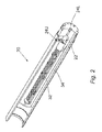
- Fig. 2 also shows that the electronics housing 20 is provided with a conduit 34 formed all the way longitudinally through it where the conduit 34 provides a flow path for drilling mud such that the drilling mud that is required for the cleaning of the inner barrel 14 (prior to the start of the coring operations) can pass through the electronics housing 20 without coming into contact with the electronics board 32.
- drilling mud and fluid is able to flow through annulus 36 and through conduit 34.
- the portion of the fluid flowing through conduit 34 can enter inside the inner core barrel 24 to clean away any debris which may have accumulated.
- ball 25 is dropped from the surface and when in position as shown in Fig. 1 , closes fluid flow through conduit 34.
- any mud being pumped from the surface through the coring apparatus 10 flows through the annulus 36 provided between the inner, and outer, core barrel.
Landscapes
- Life Sciences & Earth Sciences (AREA)
- Geology (AREA)
- Engineering & Computer Science (AREA)
- Mining & Mineral Resources (AREA)
- Physics & Mathematics (AREA)
- Environmental & Geological Engineering (AREA)
- Fluid Mechanics (AREA)
- General Life Sciences & Earth Sciences (AREA)
- Geochemistry & Mineralogy (AREA)
- Soil Sciences (AREA)
- Sampling And Sample Adjustment (AREA)
- Measuring Fluid Pressure (AREA)
- Force Measurement Appropriate To Specific Purposes (AREA)
Applications Claiming Priority (1)
| Application Number | Priority Date | Filing Date | Title |
|---|---|---|---|
| GBGB0724972.5A GB0724972D0 (en) | 2007-12-21 | 2007-12-21 | Monitoring apparatus for core barrel operations |
Publications (3)
| Publication Number | Publication Date |
|---|---|
| EP2072749A2 true EP2072749A2 (de) | 2009-06-24 |
| EP2072749A3 EP2072749A3 (de) | 2011-01-19 |
| EP2072749B1 EP2072749B1 (de) | 2012-07-11 |
Family
ID=39048542
Family Applications (1)
| Application Number | Title | Priority Date | Filing Date |
|---|---|---|---|
| EP08172350A Active EP2072749B1 (de) | 2007-12-21 | 2008-12-19 | Vorrichtung zum Überwachen das Betriebs eines Kernbehälters |
Country Status (3)
| Country | Link |
|---|---|
| US (3) | US7878269B2 (de) |
| EP (1) | EP2072749B1 (de) |
| GB (1) | GB0724972D0 (de) |
Cited By (3)
| Publication number | Priority date | Publication date | Assignee | Title |
|---|---|---|---|---|
| CN104179469A (zh) * | 2014-08-07 | 2014-12-03 | 中国海洋石油总公司 | 一种主动保压取芯工具及其使用方法 |
| EP2780742A4 (de) * | 2011-11-09 | 2015-10-14 | Halliburton Energy Services Inc | Vorrichtung und verfahren zur überwachung eines kerns während kernbohrungsoperationen |
| CN109798107A (zh) * | 2019-02-21 | 2019-05-24 | 武昌理工学院 | 一种地层岩性分析装置及分析方法 |
Families Citing this family (28)
| Publication number | Priority date | Publication date | Assignee | Title |
|---|---|---|---|---|
| EP2069605A1 (de) * | 2006-09-21 | 2009-06-17 | Coretrack Ltd | Bohrkernbehältervolumenmessgerät |
| GB0724972D0 (en) * | 2007-12-21 | 2008-01-30 | Corpro Systems Ltd | Monitoring apparatus for core barrel operations |
| US8511400B2 (en) | 2010-04-05 | 2013-08-20 | Schlumberger Technology Corporation | Apparatus and method for acoustic measurements while using a coring tool |
| WO2011127374A1 (en) | 2010-04-09 | 2011-10-13 | Bp Corporation North America Inc. | Apparatus and methods for detecting gases during coring operations |
| US8689903B2 (en) * | 2010-04-14 | 2014-04-08 | Baker Hughes Incorporated | Coring apparatus and methods |
| CN102425376B (zh) * | 2011-09-23 | 2014-05-28 | 北京市三一重机有限公司 | 一种旋挖钻机用的钻具及包括该钻具的旋挖钻机 |
| US8797035B2 (en) | 2011-11-09 | 2014-08-05 | Halliburton Energy Services, Inc. | Apparatus and methods for monitoring a core during coring operations |
| US8854044B2 (en) * | 2011-11-09 | 2014-10-07 | Haliburton Energy Services, Inc. | Instrumented core barrels and methods of monitoring a core while the core is being cut |
| US10066455B2 (en) * | 2012-02-28 | 2018-09-04 | Globaltech Corporation Pty Ltd. | Downhole surveying and core sample orientation systems, devices and methods |
| US20150337654A1 (en) * | 2013-02-05 | 2015-11-26 | Sadi Sami Ahmad ALSHANNAQ | Obtaining a downhole core sample measurement using logging while coring |
| CA2848990C (en) | 2013-04-15 | 2018-03-27 | National Oilwell Varco, L.P. | Pressure core barrel for retention of core fluids and related method |
| US10047581B2 (en) | 2014-04-21 | 2018-08-14 | Longyear Tm, Inc. | Core barrel head assembly with an integrated sample orientation tool and system for using same |
| US11125038B2 (en) * | 2014-08-27 | 2021-09-21 | Globaltech Corporation Pty Ltd | Downhole surveying and core sample orientation systems, devices and methods |
| CN104198219A (zh) * | 2014-08-27 | 2014-12-10 | 山东科技大学 | 可自动调节钻头转速的实验室用钻孔取芯机 |
| EP3204593B1 (de) * | 2014-10-10 | 2023-06-07 | Specialised Oilfield Services Pty Ltd | Verfahren und system zur verwendung bei der überwachung von kernbohrungsoperationen |
| JP6542087B2 (ja) * | 2015-09-29 | 2019-07-10 | 鹿島建設株式会社 | 地盤削孔における地下水計測方法及び削孔ロッド |
| CN107290175B (zh) * | 2017-08-10 | 2019-06-07 | 西南石油大学 | 一种便携野外岩石取样装置及方法 |
| US11078787B2 (en) | 2018-01-29 | 2021-08-03 | Baker Hughes, A Ge Company, Llc | Estimating properties of a subterranean formation |
| US10975683B2 (en) * | 2018-02-08 | 2021-04-13 | Baker Hughes Holdings Llc | Coring tools enabling measurement of dynamic responses of inner barrels and related methods |
| CN108915772B (zh) * | 2018-07-16 | 2024-04-12 | 河南理工大学 | 连续采集取芯过程煤芯温度和钻孔位置信息的装置和方法 |
| US11573156B2 (en) * | 2019-01-15 | 2023-02-07 | Westinghouse Electric Company Llc | Minimally invasive microsampler for intact removal of surface deposits and substrates |
| US11408856B2 (en) | 2020-01-03 | 2022-08-09 | Saudi Arabian Oil Company | Systems and methods for monitoring health of core samples |
| US20210246747A1 (en) * | 2020-02-06 | 2021-08-12 | Professional Directional Inc. | Method and apparatus to recover cores from downhole environments |
| CN111502579B (zh) * | 2020-04-27 | 2024-09-03 | 四川大学 | 一种自动报警的坑道保压取芯装备 |
| US11639647B2 (en) * | 2020-07-31 | 2023-05-02 | Saudi Arabian Oil Company | Self-powered sensors for detecting downhole parameters |
| CN113482563B (zh) * | 2021-08-12 | 2023-01-24 | 深圳大学 | 化学保温保压取芯器 |
| CA3183779C (en) * | 2021-12-09 | 2026-04-07 | Precise Drilling Components Ltd | Hole opener |
| CN116752961B (zh) * | 2023-06-27 | 2026-02-06 | 中冶武勘工程技术有限公司 | 一种用于破碎灰岩地层的钻进取样装置及方法 |
Citations (2)
| Publication number | Priority date | Publication date | Assignee | Title |
|---|---|---|---|---|
| US4955438A (en) | 1988-04-22 | 1990-09-11 | Eastman Christensen Company | Core drilling tool |
| WO2006058377A1 (en) | 2004-12-02 | 2006-06-08 | Coretrack Ltd | Core barrel capacity gauge |
Family Cites Families (13)
| Publication number | Priority date | Publication date | Assignee | Title |
|---|---|---|---|---|
| US3363703A (en) * | 1964-11-06 | 1968-01-16 | Shewmake Parkes | Orientation coring tool |
| US4499955A (en) * | 1983-08-12 | 1985-02-19 | Chevron Research Company | Battery powered means and method for facilitating measurements while coring |
| US5010765A (en) * | 1989-08-25 | 1991-04-30 | Teleco Oilfield Services Inc. | Method of monitoring core sampling during borehole drilling |
| GB9016624D0 (en) * | 1990-07-28 | 1990-09-12 | Corpro Systems Ltd | A sampling device |
| US5417295A (en) * | 1993-06-16 | 1995-05-23 | Sperry Sun Drilling Services, Inc. | Method and system for the early detection of the jamming of a core sampling device in an earth borehole, and for taking remedial action responsive thereto |
| US5568838A (en) * | 1994-09-23 | 1996-10-29 | Baker Hughes Incorporated | Bit-stabilized combination coring and drilling system |
| US6003620A (en) * | 1996-07-26 | 1999-12-21 | Advanced Coring Technology, Inc. | Downhole in-situ measurement of physical and or chemical properties including fluid saturations of cores while coring |
| US5984023A (en) * | 1996-07-26 | 1999-11-16 | Advanced Coring Technology | Downhole in-situ measurement of physical and or chemical properties including fluid saturations of cores while coring |
| US6216804B1 (en) * | 1998-07-29 | 2001-04-17 | James T. Aumann | Apparatus for recovering core samples under pressure |
| US6457538B1 (en) * | 2000-02-29 | 2002-10-01 | Maurer Engineering, Inc. | Advanced coring apparatus and method |
| EP2069605A1 (de) * | 2006-09-21 | 2009-06-17 | Coretrack Ltd | Bohrkernbehältervolumenmessgerät |
| US20090105955A1 (en) * | 2007-09-25 | 2009-04-23 | Baker Hughes Incorporated | Sensors For Estimating Properties Of A Core |
| GB0724972D0 (en) * | 2007-12-21 | 2008-01-30 | Corpro Systems Ltd | Monitoring apparatus for core barrel operations |
-
2007
- 2007-12-21 GB GBGB0724972.5A patent/GB0724972D0/en not_active Ceased
-
2008
- 2008-12-19 EP EP08172350A patent/EP2072749B1/de active Active
- 2008-12-22 US US12/341,466 patent/US7878269B2/en active Active
-
2010
- 2010-12-21 US US12/974,445 patent/US8146684B2/en active Active
-
2012
- 2012-02-22 US US13/402,353 patent/US8297376B2/en active Active
Patent Citations (2)
| Publication number | Priority date | Publication date | Assignee | Title |
|---|---|---|---|---|
| US4955438A (en) | 1988-04-22 | 1990-09-11 | Eastman Christensen Company | Core drilling tool |
| WO2006058377A1 (en) | 2004-12-02 | 2006-06-08 | Coretrack Ltd | Core barrel capacity gauge |
Cited By (4)
| Publication number | Priority date | Publication date | Assignee | Title |
|---|---|---|---|---|
| EP2780742A4 (de) * | 2011-11-09 | 2015-10-14 | Halliburton Energy Services Inc | Vorrichtung und verfahren zur überwachung eines kerns während kernbohrungsoperationen |
| CN104179469A (zh) * | 2014-08-07 | 2014-12-03 | 中国海洋石油总公司 | 一种主动保压取芯工具及其使用方法 |
| CN104179469B (zh) * | 2014-08-07 | 2017-01-25 | 中国海洋石油总公司 | 一种主动保压取芯工具及其使用方法 |
| CN109798107A (zh) * | 2019-02-21 | 2019-05-24 | 武昌理工学院 | 一种地层岩性分析装置及分析方法 |
Also Published As
| Publication number | Publication date |
|---|---|
| GB0724972D0 (en) | 2008-01-30 |
| US8297376B2 (en) | 2012-10-30 |
| US7878269B2 (en) | 2011-02-01 |
| US20090159335A1 (en) | 2009-06-25 |
| US8146684B2 (en) | 2012-04-03 |
| EP2072749A3 (de) | 2011-01-19 |
| US20120145461A1 (en) | 2012-06-14 |
| US20110083905A1 (en) | 2011-04-14 |
| EP2072749B1 (de) | 2012-07-11 |
Similar Documents
| Publication | Publication Date | Title |
|---|---|---|
| EP2072749B1 (de) | Vorrichtung zum Überwachen das Betriebs eines Kernbehälters | |
| US10577880B2 (en) | Device and system for use in monitoring coring operations | |
| US6986282B2 (en) | Method and apparatus for determining downhole pressures during a drilling operation | |
| US8136591B2 (en) | Method and system for using wireline configurable wellbore instruments with a wired pipe string | |
| CA2929973C (en) | Borehole logging methods and apparatus | |
| US20230374899A1 (en) | Method and system for determining core orientation | |
| US7665542B2 (en) | Core barrel capacity gauge and method | |
| WO2016176257A1 (en) | Methods of plotting advanced logging information | |
| US20090107724A1 (en) | Method and apparatus for continuous formation sampling and analysis during wellbore drilling | |
| US11608735B2 (en) | Drill bit position measurement | |
| US11732537B2 (en) | Anchor point device for formation testing relative measurements | |
| US8272260B2 (en) | Method and apparatus for formation evaluation after drilling | |
| Harrison et al. | Probing the till beneath black rapids glacier, alaska, usa | |
| EP1911928A1 (de) | Vorrichtung und Verfahren zur Erkennung von Kohlenwasserstoffen während des Bohrens | |
| CA3052073C (en) | Method and system for determining core orientation |
Legal Events
| Date | Code | Title | Description |
|---|---|---|---|
| PUAI | Public reference made under article 153(3) epc to a published international application that has entered the european phase |
Free format text: ORIGINAL CODE: 0009012 |
|
| AK | Designated contracting states |
Kind code of ref document: A2 Designated state(s): AT BE BG CH CY CZ DE DK EE ES FI FR GB GR HR HU IE IS IT LI LT LU LV MC MT NL NO PL PT RO SE SI SK TR |
|
| AX | Request for extension of the european patent |
Extension state: AL BA MK RS |
|
| PUAL | Search report despatched |
Free format text: ORIGINAL CODE: 0009013 |
|
| AK | Designated contracting states |
Kind code of ref document: A3 Designated state(s): AT BE BG CH CY CZ DE DK EE ES FI FR GB GR HR HU IE IS IT LI LT LU LV MC MT NL NO PL PT RO SE SI SK TR |
|
| AX | Request for extension of the european patent |
Extension state: AL BA MK RS |
|
| 17P | Request for examination filed |
Effective date: 20110719 |
|
| AKX | Designation fees paid |
Designated state(s): AT BE BG CH CY LI |
|
| RBV | Designated contracting states (corrected) |
Designated state(s): AT BE BG CH CY CZ LI |
|
| RBV | Designated contracting states (corrected) |
Designated state(s): AT BE BG CH CY CZ DE DK EE ES FI FR GB GR HR HU IE IS IT LI LT LU LV MC MT NL NO PL PT RO SE SI SK TR |
|
| REG | Reference to a national code |
Ref country code: DE Ref legal event code: R108 Ref document number: 602008017080 Country of ref document: DE Effective date: 20110921 |
|
| 17Q | First examination report despatched |
Effective date: 20111111 |
|
| GRAP | Despatch of communication of intention to grant a patent |
Free format text: ORIGINAL CODE: EPIDOSNIGR1 |
|
| GRAS | Grant fee paid |
Free format text: ORIGINAL CODE: EPIDOSNIGR3 |
|
| GRAA | (expected) grant |
Free format text: ORIGINAL CODE: 0009210 |
|
| RIN1 | Information on inventor provided before grant (corrected) |
Inventor name: CRAVATTE, PHILLIPE |
|
| AK | Designated contracting states |
Kind code of ref document: B1 Designated state(s): AT BE BG CH CY CZ DE DK EE ES FI FR GB GR HR HU IE IS IT LI LT LU LV MC MT NL NO PL PT RO SE SI SK TR |
|
| REG | Reference to a national code |
Ref country code: GB Ref legal event code: FG4D |
|
| REG | Reference to a national code |
Ref country code: CH Ref legal event code: EP |
|
| REG | Reference to a national code |
Ref country code: AT Ref legal event code: REF Ref document number: 566246 Country of ref document: AT Kind code of ref document: T Effective date: 20120715 |
|
| REG | Reference to a national code |
Ref country code: IE Ref legal event code: FG4D |
|
| REG | Reference to a national code |
Ref country code: DE Ref legal event code: R096 Ref document number: 602008017080 Country of ref document: DE Effective date: 20120906 |
|
| REG | Reference to a national code |
Ref country code: DE Ref legal event code: R082 Ref document number: 602008017080 Country of ref document: DE Representative=s name: PATENTANWALTSKANZLEI MEYER, DE |
|
| REG | Reference to a national code |
Ref country code: NL Ref legal event code: T3 |
|
| REG | Reference to a national code |
Ref country code: AT Ref legal event code: MK05 Ref document number: 566246 Country of ref document: AT Kind code of ref document: T Effective date: 20120711 |
|
| REG | Reference to a national code |
Ref country code: LT Ref legal event code: MG4D Effective date: 20120711 |
|
| PG25 | Lapsed in a contracting state [announced via postgrant information from national office to epo] |
Ref country code: CY Free format text: LAPSE BECAUSE OF FAILURE TO SUBMIT A TRANSLATION OF THE DESCRIPTION OR TO PAY THE FEE WITHIN THE PRESCRIBED TIME-LIMIT Effective date: 20120711 Ref country code: HR Free format text: LAPSE BECAUSE OF FAILURE TO SUBMIT A TRANSLATION OF THE DESCRIPTION OR TO PAY THE FEE WITHIN THE PRESCRIBED TIME-LIMIT Effective date: 20120711 Ref country code: LT Free format text: LAPSE BECAUSE OF FAILURE TO SUBMIT A TRANSLATION OF THE DESCRIPTION OR TO PAY THE FEE WITHIN THE PRESCRIBED TIME-LIMIT Effective date: 20120711 Ref country code: NO Free format text: LAPSE BECAUSE OF FAILURE TO SUBMIT A TRANSLATION OF THE DESCRIPTION OR TO PAY THE FEE WITHIN THE PRESCRIBED TIME-LIMIT Effective date: 20121011 Ref country code: FI Free format text: LAPSE BECAUSE OF FAILURE TO SUBMIT A TRANSLATION OF THE DESCRIPTION OR TO PAY THE FEE WITHIN THE PRESCRIBED TIME-LIMIT Effective date: 20120711 Ref country code: AT Free format text: LAPSE BECAUSE OF FAILURE TO SUBMIT A TRANSLATION OF THE DESCRIPTION OR TO PAY THE FEE WITHIN THE PRESCRIBED TIME-LIMIT Effective date: 20120711 Ref country code: IS Free format text: LAPSE BECAUSE OF FAILURE TO SUBMIT A TRANSLATION OF THE DESCRIPTION OR TO PAY THE FEE WITHIN THE PRESCRIBED TIME-LIMIT Effective date: 20121111 Ref country code: BE Free format text: LAPSE BECAUSE OF FAILURE TO SUBMIT A TRANSLATION OF THE DESCRIPTION OR TO PAY THE FEE WITHIN THE PRESCRIBED TIME-LIMIT Effective date: 20120711 |
|
| PG25 | Lapsed in a contracting state [announced via postgrant information from national office to epo] |
Ref country code: PL Free format text: LAPSE BECAUSE OF FAILURE TO SUBMIT A TRANSLATION OF THE DESCRIPTION OR TO PAY THE FEE WITHIN THE PRESCRIBED TIME-LIMIT Effective date: 20120711 Ref country code: SE Free format text: LAPSE BECAUSE OF FAILURE TO SUBMIT A TRANSLATION OF THE DESCRIPTION OR TO PAY THE FEE WITHIN THE PRESCRIBED TIME-LIMIT Effective date: 20120711 Ref country code: GR Free format text: LAPSE BECAUSE OF FAILURE TO SUBMIT A TRANSLATION OF THE DESCRIPTION OR TO PAY THE FEE WITHIN THE PRESCRIBED TIME-LIMIT Effective date: 20121012 Ref country code: SI Free format text: LAPSE BECAUSE OF FAILURE TO SUBMIT A TRANSLATION OF THE DESCRIPTION OR TO PAY THE FEE WITHIN THE PRESCRIBED TIME-LIMIT Effective date: 20120711 Ref country code: LV Free format text: LAPSE BECAUSE OF FAILURE TO SUBMIT A TRANSLATION OF THE DESCRIPTION OR TO PAY THE FEE WITHIN THE PRESCRIBED TIME-LIMIT Effective date: 20120711 Ref country code: PT Free format text: LAPSE BECAUSE OF FAILURE TO SUBMIT A TRANSLATION OF THE DESCRIPTION OR TO PAY THE FEE WITHIN THE PRESCRIBED TIME-LIMIT Effective date: 20121112 |
|
| PG25 | Lapsed in a contracting state [announced via postgrant information from national office to epo] |
Ref country code: RO Free format text: LAPSE BECAUSE OF FAILURE TO SUBMIT A TRANSLATION OF THE DESCRIPTION OR TO PAY THE FEE WITHIN THE PRESCRIBED TIME-LIMIT Effective date: 20120711 Ref country code: DK Free format text: LAPSE BECAUSE OF FAILURE TO SUBMIT A TRANSLATION OF THE DESCRIPTION OR TO PAY THE FEE WITHIN THE PRESCRIBED TIME-LIMIT Effective date: 20120711 Ref country code: ES Free format text: LAPSE BECAUSE OF FAILURE TO SUBMIT A TRANSLATION OF THE DESCRIPTION OR TO PAY THE FEE WITHIN THE PRESCRIBED TIME-LIMIT Effective date: 20121022 Ref country code: EE Free format text: LAPSE BECAUSE OF FAILURE TO SUBMIT A TRANSLATION OF THE DESCRIPTION OR TO PAY THE FEE WITHIN THE PRESCRIBED TIME-LIMIT Effective date: 20120711 Ref country code: CZ Free format text: LAPSE BECAUSE OF FAILURE TO SUBMIT A TRANSLATION OF THE DESCRIPTION OR TO PAY THE FEE WITHIN THE PRESCRIBED TIME-LIMIT Effective date: 20120711 |
|
| PLBE | No opposition filed within time limit |
Free format text: ORIGINAL CODE: 0009261 |
|
| STAA | Information on the status of an ep patent application or granted ep patent |
Free format text: STATUS: NO OPPOSITION FILED WITHIN TIME LIMIT |
|
| PG25 | Lapsed in a contracting state [announced via postgrant information from national office to epo] |
Ref country code: SK Free format text: LAPSE BECAUSE OF FAILURE TO SUBMIT A TRANSLATION OF THE DESCRIPTION OR TO PAY THE FEE WITHIN THE PRESCRIBED TIME-LIMIT Effective date: 20120711 Ref country code: IT Free format text: LAPSE BECAUSE OF FAILURE TO SUBMIT A TRANSLATION OF THE DESCRIPTION OR TO PAY THE FEE WITHIN THE PRESCRIBED TIME-LIMIT Effective date: 20120711 |
|
| 26N | No opposition filed |
Effective date: 20130412 |
|
| PG25 | Lapsed in a contracting state [announced via postgrant information from national office to epo] |
Ref country code: MC Free format text: LAPSE BECAUSE OF NON-PAYMENT OF DUE FEES Effective date: 20121231 Ref country code: BG Free format text: LAPSE BECAUSE OF FAILURE TO SUBMIT A TRANSLATION OF THE DESCRIPTION OR TO PAY THE FEE WITHIN THE PRESCRIBED TIME-LIMIT Effective date: 20121011 |
|
| REG | Reference to a national code |
Ref country code: CH Ref legal event code: PL |
|
| REG | Reference to a national code |
Ref country code: DE Ref legal event code: R097 Ref document number: 602008017080 Country of ref document: DE Effective date: 20130412 |
|
| REG | Reference to a national code |
Ref country code: IE Ref legal event code: MM4A |
|
| PG25 | Lapsed in a contracting state [announced via postgrant information from national office to epo] |
Ref country code: IE Free format text: LAPSE BECAUSE OF NON-PAYMENT OF DUE FEES Effective date: 20121219 Ref country code: CH Free format text: LAPSE BECAUSE OF NON-PAYMENT OF DUE FEES Effective date: 20121231 Ref country code: LI Free format text: LAPSE BECAUSE OF NON-PAYMENT OF DUE FEES Effective date: 20121231 |
|
| PG25 | Lapsed in a contracting state [announced via postgrant information from national office to epo] |
Ref country code: MT Free format text: LAPSE BECAUSE OF FAILURE TO SUBMIT A TRANSLATION OF THE DESCRIPTION OR TO PAY THE FEE WITHIN THE PRESCRIBED TIME-LIMIT Effective date: 20120711 |
|
| PG25 | Lapsed in a contracting state [announced via postgrant information from national office to epo] |
Ref country code: TR Free format text: LAPSE BECAUSE OF FAILURE TO SUBMIT A TRANSLATION OF THE DESCRIPTION OR TO PAY THE FEE WITHIN THE PRESCRIBED TIME-LIMIT Effective date: 20120711 |
|
| PG25 | Lapsed in a contracting state [announced via postgrant information from national office to epo] |
Ref country code: LU Free format text: LAPSE BECAUSE OF NON-PAYMENT OF DUE FEES Effective date: 20121219 |
|
| PG25 | Lapsed in a contracting state [announced via postgrant information from national office to epo] |
Ref country code: HU Free format text: LAPSE BECAUSE OF FAILURE TO SUBMIT A TRANSLATION OF THE DESCRIPTION OR TO PAY THE FEE WITHIN THE PRESCRIBED TIME-LIMIT Effective date: 20081219 |
|
| REG | Reference to a national code |
Ref country code: FR Ref legal event code: PLFP Year of fee payment: 8 |
|
| REG | Reference to a national code |
Ref country code: FR Ref legal event code: PLFP Year of fee payment: 9 |
|
| REG | Reference to a national code |
Ref country code: FR Ref legal event code: PLFP Year of fee payment: 10 |
|
| PGFP | Annual fee paid to national office [announced via postgrant information from national office to epo] |
Ref country code: GB Payment date: 20251215 Year of fee payment: 18 |
|
| PGFP | Annual fee paid to national office [announced via postgrant information from national office to epo] |
Ref country code: NL Payment date: 20251222 Year of fee payment: 18 Ref country code: FR Payment date: 20251219 Year of fee payment: 18 |
|
| PGFP | Annual fee paid to national office [announced via postgrant information from national office to epo] |
Ref country code: DE Payment date: 20251217 Year of fee payment: 18 |