EP2072764A2 - Palier axial - Google Patents
Palier axial Download PDFInfo
- Publication number
- EP2072764A2 EP2072764A2 EP08170223A EP08170223A EP2072764A2 EP 2072764 A2 EP2072764 A2 EP 2072764A2 EP 08170223 A EP08170223 A EP 08170223A EP 08170223 A EP08170223 A EP 08170223A EP 2072764 A2 EP2072764 A2 EP 2072764A2
- Authority
- EP
- European Patent Office
- Prior art keywords
- thrust bearing
- lubricant
- bearing
- axial
- axial bearing
- Prior art date
- Legal status (The legal status is an assumption and is not a legal conclusion. Google has not performed a legal analysis and makes no representation as to the accuracy of the status listed.)
- Granted
Links
- 239000000314 lubricant Substances 0.000 claims abstract description 62
- 238000005461 lubrication Methods 0.000 claims description 12
- 238000004519 manufacturing process Methods 0.000 description 9
- 238000009826 distribution Methods 0.000 description 4
- 239000011343 solid material Substances 0.000 description 4
- 230000001050 lubricating effect Effects 0.000 description 3
- 239000010687 lubricating oil Substances 0.000 description 3
- 239000000463 material Substances 0.000 description 3
- 239000003921 oil Substances 0.000 description 3
- 238000005304 joining Methods 0.000 description 2
- 238000003825 pressing Methods 0.000 description 2
- 238000010408 sweeping Methods 0.000 description 2
- 238000003339 best practice Methods 0.000 description 1
- 238000002485 combustion reaction Methods 0.000 description 1
- 238000010276 construction Methods 0.000 description 1
- 238000004049 embossing Methods 0.000 description 1
- 238000005538 encapsulation Methods 0.000 description 1
- 238000005516 engineering process Methods 0.000 description 1
- 239000011796 hollow space material Substances 0.000 description 1
- 238000009434 installation Methods 0.000 description 1
- 239000010705 motor oil Substances 0.000 description 1
- 238000004080 punching Methods 0.000 description 1
- 238000007789 sealing Methods 0.000 description 1
- 239000007787 solid Substances 0.000 description 1
Images
Classifications
-
- F—MECHANICAL ENGINEERING; LIGHTING; HEATING; WEAPONS; BLASTING
- F01—MACHINES OR ENGINES IN GENERAL; ENGINE PLANTS IN GENERAL; STEAM ENGINES
- F01D—NON-POSITIVE DISPLACEMENT MACHINES OR ENGINES, e.g. STEAM TURBINES
- F01D25/00—Component parts, details, or accessories, not provided for in, or of interest apart from, other groups
- F01D25/16—Arrangement of bearings; Supporting or mounting bearings in casings
- F01D25/166—Sliding contact bearing
- F01D25/168—Sliding contact bearing for axial load mainly
-
- F—MECHANICAL ENGINEERING; LIGHTING; HEATING; WEAPONS; BLASTING
- F16—ENGINEERING ELEMENTS AND UNITS; GENERAL MEASURES FOR PRODUCING AND MAINTAINING EFFECTIVE FUNCTIONING OF MACHINES OR INSTALLATIONS; THERMAL INSULATION IN GENERAL
- F16C—SHAFTS; FLEXIBLE SHAFTS; ELEMENTS OR CRANKSHAFT MECHANISMS; ROTARY BODIES OTHER THAN GEARING ELEMENTS; BEARINGS
- F16C17/00—Sliding-contact bearings for exclusively rotary movement
- F16C17/04—Sliding-contact bearings for exclusively rotary movement for axial load only
- F16C17/047—Sliding-contact bearings for exclusively rotary movement for axial load only with fixed wedges to generate hydrodynamic pressure
-
- F—MECHANICAL ENGINEERING; LIGHTING; HEATING; WEAPONS; BLASTING
- F16—ENGINEERING ELEMENTS AND UNITS; GENERAL MEASURES FOR PRODUCING AND MAINTAINING EFFECTIVE FUNCTIONING OF MACHINES OR INSTALLATIONS; THERMAL INSULATION IN GENERAL
- F16C—SHAFTS; FLEXIBLE SHAFTS; ELEMENTS OR CRANKSHAFT MECHANISMS; ROTARY BODIES OTHER THAN GEARING ELEMENTS; BEARINGS
- F16C33/00—Parts of bearings; Special methods for making bearings or parts thereof
- F16C33/02—Parts of sliding-contact bearings
- F16C33/04—Brasses; Bushes; Linings
- F16C33/06—Sliding surface mainly made of metal
- F16C33/10—Construction relative to lubrication
- F16C33/1025—Construction relative to lubrication with liquid, e.g. oil, as lubricant
- F16C33/106—Details of distribution or circulation inside the bearings, e.g. details of the bearing surfaces to affect flow or pressure of the liquid
- F16C33/1075—Wedges, e.g. ramps or lobes, for generating pressure
-
- F—MECHANICAL ENGINEERING; LIGHTING; HEATING; WEAPONS; BLASTING
- F05—INDEXING SCHEMES RELATING TO ENGINES OR PUMPS IN VARIOUS SUBCLASSES OF CLASSES F01-F04
- F05D—INDEXING SCHEME FOR ASPECTS RELATING TO NON-POSITIVE-DISPLACEMENT MACHINES OR ENGINES, GAS-TURBINES OR JET-PROPULSION PLANTS
- F05D2220/00—Application
- F05D2220/40—Application in turbochargers
-
- F—MECHANICAL ENGINEERING; LIGHTING; HEATING; WEAPONS; BLASTING
- F05—INDEXING SCHEMES RELATING TO ENGINES OR PUMPS IN VARIOUS SUBCLASSES OF CLASSES F01-F04
- F05D—INDEXING SCHEME FOR ASPECTS RELATING TO NON-POSITIVE-DISPLACEMENT MACHINES OR ENGINES, GAS-TURBINES OR JET-PROPULSION PLANTS
- F05D2230/00—Manufacture
- F05D2230/50—Building or constructing in particular ways
-
- F—MECHANICAL ENGINEERING; LIGHTING; HEATING; WEAPONS; BLASTING
- F05—INDEXING SCHEMES RELATING TO ENGINES OR PUMPS IN VARIOUS SUBCLASSES OF CLASSES F01-F04
- F05D—INDEXING SCHEME FOR ASPECTS RELATING TO NON-POSITIVE-DISPLACEMENT MACHINES OR ENGINES, GAS-TURBINES OR JET-PROPULSION PLANTS
- F05D2240/00—Components
- F05D2240/50—Bearings
- F05D2240/53—Hydrodynamic or hydrostatic bearings
-
- F—MECHANICAL ENGINEERING; LIGHTING; HEATING; WEAPONS; BLASTING
- F16—ENGINEERING ELEMENTS AND UNITS; GENERAL MEASURES FOR PRODUCING AND MAINTAINING EFFECTIVE FUNCTIONING OF MACHINES OR INSTALLATIONS; THERMAL INSULATION IN GENERAL
- F16C—SHAFTS; FLEXIBLE SHAFTS; ELEMENTS OR CRANKSHAFT MECHANISMS; ROTARY BODIES OTHER THAN GEARING ELEMENTS; BEARINGS
- F16C2360/00—Engines or pumps
- F16C2360/23—Gas turbine engines
- F16C2360/24—Turbochargers
Definitions
- Out EP 0 160 460 A2 is a charging device, which is designed as an exhaust gas turbocharger known.
- the exhaust gas turbocharger comprises a turbine housing with a channel through which exhaust gas from an internal combustion engine is passed through an annular passage to the turbine and a nozzle ring, a number of blades which are arranged in the annular channel and rotatably mounted on the nozzle ring and a device for Twisting of the blades.
- How out EP 0 160 460 A2 shows runs between the turbine impeller of the turbine part and the compressor impeller of the compressor part of the exhaust gas turbocharger a shaft. This continuous shaft is mounted in the housing of the exhaust gas turbocharger in a thrust bearing.
- a lubricating medium such as filtered engine oil
- the bore system extends to the bearings of the shaft on which the turbine runner and compressor runner are received.
- the plain bearings are connected via channels with an oil supply hole.
- the oil supply bore extending essentially in the horizontal direction through the housing of the charging device is in turn charged with the lubricating medium via a connecting piece.
- the thrust bearing of the supercharger it is proposed to divide the thrust bearing of the supercharger and represent as two similar components and to reduce in this way the manufacturing cost of the thrust bearing.
- the functional surfaces e.g. To represent wedge surfaces for generating the carrying capacity and locking surfaces in opposite directions.
- the respective blank of the two components of the thrust bearing can be identical, and only the finishing of the two components representing the thrust bearing is different.
- lubricant channels are embossed or stamped in at least one side of two shell-shaped bodies on the rear side of the wedge surfaces .
- the lubricant channels may also be stamped or otherwise formed on facing back sides of the split thrust bearing.
- a central lubricant channel has a kidney-shaped contour. From this central, kidney-shaped running lubricant channel branch off a number of puncture channels, are supplied via the individual outlet openings, which open into the wedge surfaces, with lubricant.
- the central kidney-shaped lubricant channel can be acted upon by the lubricant via a centrally located central lubricant inlet, for example.
- a bore extending in relation to its diameter in the material of a thrust ring designed as thrust ring can be saved, without the lubricant supply, in particular the functional surfaces designed as wedge surfaces would endangered at least one front of the thrust bearing.
- the proposed solution according to the invention in the Series production due to the use of best practices are made very rational.
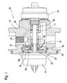
- the representation according to FIG. 1 is a section through a shaft bearing of a trained as exhaust gas turbocharger charger 10 can be seen.
- FIG. 1 From the sectional view according to FIG. 1 shows that within a housing part 12 of the charging device 10, a shaft 11 extends, which is rotatably mounted on bushes 28, 30 in the housing part 12 of the charging device 10.
- the shaft 11 is in the embodiment according to FIG. 1 mounted in the housing part 12 by means of the two sleeves 28, 30 which are spaced from one another in the axial direction.
- Reference numeral 18 designates a 1. runner shoulder, reference numeral 20 denotes a second run-on shoulder.
- FIG. 1 shows that the closed thrust bearing 22 is disposed in the housing part 12 of the charging device 10. How out FIG. 1 can be removed, is located in the housing part 12 of the charging device 10, a terminal 24 for a lubricant supply and a lubricant bore 26. Via the terminal 24, the lubricant enters the running through the housing part 12 the lubricant bore 26 and is to the jacks 28, 30, which radially support the shaft 11 in the housing part 12, and guided in the closed axial bearing 22.
- the thrust bearing 22 has at least at one end face on a number of functional surfaces. These include (see illustration according to FIG. 2 ) Locking surfaces 46, wedge surfaces 48 and into these opening outlets 44 for the lubricant.
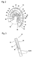
- FIG. 2 is a perspective view of the front of the thrust bearing 22 can be seen.
- the perspective top view of the front side of the axial bearing 40 shows that the axial bearing 22 has a number of annularly arranged latching surfaces 46 and wedge surfaces 48 on its front side 42.
- the ring-shaped on the front side 42 of the thrust bearing 40 according to the perspective view in FIG. 2 distributed surfaces 46, 48 are supplied via a respective outlet bore 44 with lubricant. Due to the arrangement of locking surfaces 46 and wedge surfaces 48 is carried out by supplying the lubricant, the structure of a lubricant cushion or a lubricant film, the material contact between the thrust bearing 40 and the in FIG. 1 illustrated start-up shoulders 18, 20 avoids, so that a low-friction axial bearing is created. From the illustration according to FIG.
- the thrust bearing 40 has a 90 ° recess 52 below a passage opening 56. Due to this recess 52 below the passage opening 54, a one-piece thrust bearing 40 can be formed in contrast to a closed thrust bearing 22, as in FIG. 1 represented, are very easily plugged onto the shaft 11, which has a simpler installation result. From the latter, the lubricant flows through the at least one feed bore 34, which extends substantially in the vertical direction in the solid material of the axial bearing 40, axial bores 42, which lie in the wedge surfaces 48 to.
- the thrust bearing 22 used there is designed in a closed design and is located between a first thrust shoulder 18 (track disc) and a second thrust shoulder 20 (track disc).
- a first thrust shoulder 18 track disc
- a second thrust shoulder 20 track disc
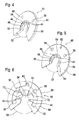
- FIG. 3 makes a cut through the in FIG. 2 shows axial bearing 22 shown in perspective, it can be seen that the supply bore 34 extends through the solid material of the integrally formed thrust bearing. This runs in the solid material of the thrust bearing 40 and ensures the supply of lubricant to the thrust bearing 30.
- the feed bore 34 in the solid material of the thrust bearing 30 is very complicated and difficult to produce.
- a lubrication groove 50 On the back 56 is also a lubrication groove 50.
- On integrally formed thrust bearing 40 as shown in FIG. 4 are further, as in the perspective view according to FIG. 2 already indicated, passage openings (screw holes 58) executed.
- FIG. 5 shows a front side of a cup-shaped multi-part thrust bearing.
- FIG. 4 shows the perspective view of an outer side 66 of a first thrust bearing shell 68 of a split version 60 of a thrust bearing.
- the split version 60 of the thrust bearing essentially comprises the in FIG. 5 in a perspective view shown first thrust bearing 68 and another in the FIGS. 7 and 8 shown from the front and rear forth another second thrust bearing shell 70th
- the outer side 66 of the first thrust bearing 68 has in addition to the screw holes 58 and a through hole 62 for connecting a lubricant supply to the lubrication groove 50.
- wedge surfaces 48 and locking surfaces 46 are arranged in the circumferential direction successively.
- the lubricant supplied via the through-bore 62 exits via exit bores 44, which lie in the region of the wedge surfaces 48, and enables the construction of a lubricant cushion or lubricant film within the lubrication groove 50.
- exit bores 44 which lie in the region of the wedge surfaces 48
- the first axial bearing shell 68 of the axial bearing formed in a split design 60 also comprises an opening 54 for the shaft 11 (see illustration according to FIG. 1 ), which merges at the bottom in a recess 52. Accordingly also points in the FIGS. 7 and 8 shown second thrust bearing shell 70, the recess 52 to facilitate assembly.
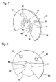
- FIG. 6 is the back of the first thrust bearing 68 according to FIG. 5 refer to.
- kidney-shaped lubricant distribution channel 32 runs in an inner side 64 of the first axial bearing shell 68.
- This is impressed, stamped or forged by means of a considerably simplified production of the axial bearing formed in the split embodiment 60 into the inside 64, ie the rear side of the first axial bearing shell 68.
- the through-hole 62 opens into the central lubricant distribution channel 32 formed kidney-shaped on the inner side 64.
- the branch channels 72 extend substantially in the radial direction with respect to the axis of symmetry of the first axial bearing shell 68 and allow the outlet bore 44 to be supplied with lubricant, which is supplied via the through-bore 62.
- FIG. 6 further shows, extends below the opening 54 for the shaft 11, the recess 52, which in the illustration in accordance with FIG. 6 and analogously in the representations according to the Figures 5 . 7 . 8th . 9 and 10 an angle in the order of about 90 ° sweeps over.
- the kidney-shaped lubricant channel 32 is narrowed by material webs which limit the screw holes 58.
- the supply of the branch channels 72 via the substantially kidney-shaped lubricant distribution channel 32 does not detract from this.
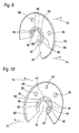
- FIG. 7 shows the outside of the second thrust bearing shell of the split thrust bearing.
- the configuration of the outer side 66 of the second thrust bearing shell 70 according to the perspective view in FIG. 7 corresponds substantially to the configuration of the outer side 66, the first thrust bearing 68 divided embodiment 60 of the thrust bearing, except for in FIG. 7 lack of through-hole 62, through which in the interior, ie the kidney-shaped lubricant distribution channel formed at the back of the first thrust bearing 68, just that lubricant is supplied.
- From the perspective reproduced view of the outer side 66 of the second thrust bearing shell 70 shows that here 50 locking surfaces 46 and wedge surfaces 48 are executed in an alternating sequence in a sequence of alternation, wherein analogous to the representations according to FIG. 5 in the wedge surfaces 48 exit holes 44 open.
- FIG. 8 shows FIG. 8 the configuration of the inner side 64 of the second thrust bearing shell 70.
- This is compared to the configuration of the inside of the first thrust bearing shell 68 as shown in FIG. 6 considerably simplified.
- the second thrust bearing shell 70 only the screw holes 58, which are aligned with those of the first thrust bearing shell 68, are executed, and the outlet bores 44, which are located on the in FIG. 7 shown outer side 66 of the second thrust bearing shell 70 in the area, preferably open centrally in the wedge surfaces 48.
- Reference numeral 52 in FIG. 8 denotes the an angle of about 90 ° sweeping recess 52 into which the opening 54 for the shaft 11 passes.
- the recess 52 serves - as already described above - to simplify the mounting of the thrust bearing 40 on the circumference of a shaft 11 - as related to FIG. 1 shown.
- FIGS. 9 and 10 It can be seen that the first thrust bearing shell 68 and the second thrust bearing shell 70 of the axial bearing 40 shown in divided execution 60 are joined together in the mounting direction 54 with inner sides 64.
- an encapsulation takes place, ie a sealing of the hollow space shown by the kidney-shaped lubricant channel 32 and the branch channels 72 branching from it. This is applied centrally via the through hole 62 with lubricant.
- a seal of the axial bearing 40 shown in divided execution 60 ie by pressing together the thrust bearing shells 68, 70 ensured.
- a split training 60 can also on a circumferentially closed executed thrust bearing 22 (see. FIGS. 2, 3 and 4 ).
- closed thrust bearings 22 not each of the wedge surfaces 48 is fed by a specially assigned outlet bore 44 with lubricant. Often even only one supply bore 34 in a vertical arrangement or only one outlet bore 44 is used, and the lubricant distributed over the centrifugal force on the intended wedge surfaces 48.
- split design 60 can, in contrast to a closed version of the thrust bearing 22 each of the wedge surfaces 48 are supplied with lubricant with little effort.
Landscapes
- Engineering & Computer Science (AREA)
- General Engineering & Computer Science (AREA)
- Mechanical Engineering (AREA)
- Physics & Mathematics (AREA)
- Fluid Mechanics (AREA)
- Chemical & Material Sciences (AREA)
- Oil, Petroleum & Natural Gas (AREA)
- Sliding-Contact Bearings (AREA)
Applications Claiming Priority (1)
| Application Number | Priority Date | Filing Date | Title |
|---|---|---|---|
| DE102007060226A DE102007060226A1 (de) | 2007-12-14 | 2007-12-14 | Axiallager |
Publications (3)
| Publication Number | Publication Date |
|---|---|
| EP2072764A2 true EP2072764A2 (fr) | 2009-06-24 |
| EP2072764A3 EP2072764A3 (fr) | 2010-04-28 |
| EP2072764B1 EP2072764B1 (fr) | 2016-03-30 |
Family
ID=40193687
Family Applications (1)
| Application Number | Title | Priority Date | Filing Date |
|---|---|---|---|
| EP08170223.5A Ceased EP2072764B1 (fr) | 2007-12-14 | 2008-11-28 | Palier axial |
Country Status (2)
| Country | Link |
|---|---|
| EP (1) | EP2072764B1 (fr) |
| DE (1) | DE102007060226A1 (fr) |
Families Citing this family (3)
| Publication number | Priority date | Publication date | Assignee | Title |
|---|---|---|---|---|
| DE102013223678A1 (de) | 2013-11-20 | 2015-06-25 | Bosch Mahle Turbo Systems Gmbh & Co. Kg | Axiallager, insbesondere für einen Abgasturbolader |
| US10590946B2 (en) | 2017-01-09 | 2020-03-17 | Borgwarner Inc. | Turbocharger having thrust bearing with biased oil flow |
| DE102020005817A1 (de) | 2020-09-24 | 2022-03-24 | Daimler Ag | Lagerungsanordnung eines Laufzeugs an elnem Gehäuse eines Abgasturboladers, insbesondere für Kraftfahrzeug |
Citations (1)
| Publication number | Priority date | Publication date | Assignee | Title |
|---|---|---|---|---|
| EP0160460A2 (fr) | 1984-04-20 | 1985-11-06 | Allied-Signal Inc. | Turbosoufflante à gaz d'échappement |
Family Cites Families (5)
| Publication number | Priority date | Publication date | Assignee | Title |
|---|---|---|---|---|
| US5178471A (en) * | 1991-05-20 | 1993-01-12 | Allied-Signal Inc. | Thrust bearing for turbocharger |
| US5857332A (en) * | 1996-12-20 | 1999-01-12 | Turbodyne Systems, Inc. | Bearing systems for motor-assisted turbochargers for internal combustion engines |
| US6669372B1 (en) * | 2002-07-30 | 2003-12-30 | Honeywell International Inc. | Turbocharger thrust bearing |
| EP1619356B1 (fr) * | 2004-07-23 | 2016-03-16 | BorgWarner, Inc. | Palier de butée pour turbocompresseur |
| US7354199B2 (en) * | 2005-06-01 | 2008-04-08 | Federal Mogul Worldwide, Inc. | Thrust bearing |
-
2007
- 2007-12-14 DE DE102007060226A patent/DE102007060226A1/de not_active Withdrawn
-
2008
- 2008-11-28 EP EP08170223.5A patent/EP2072764B1/fr not_active Ceased
Patent Citations (1)
| Publication number | Priority date | Publication date | Assignee | Title |
|---|---|---|---|---|
| EP0160460A2 (fr) | 1984-04-20 | 1985-11-06 | Allied-Signal Inc. | Turbosoufflante à gaz d'échappement |
Also Published As
| Publication number | Publication date |
|---|---|
| EP2072764B1 (fr) | 2016-03-30 |
| DE102007060226A1 (de) | 2009-06-18 |
| EP2072764A3 (fr) | 2010-04-28 |
Similar Documents
| Publication | Publication Date | Title |
|---|---|---|
| EP2193279B1 (fr) | Palier axial hydrodynamique | |
| DE10210866C5 (de) | Leitschaufelbefestigung in einem Strömungskanal einer Fluggasturbine | |
| EP3032037B1 (fr) | Stator et turbomachine | |
| EP1470348B1 (fr) | Engrenage planétaire | |
| EP1785646A1 (fr) | Porte-satellites | |
| WO2008129046A2 (fr) | Palier axial notamment pour un turbocompresseur | |
| DE112011103096B4 (de) | Abgasturbolader | |
| DE102015222270A1 (de) | Modulare turbolader-spaltdichtung | |
| EP2072764B1 (fr) | Palier axial | |
| DE10144624A1 (de) | Axiallageranordnung mit Vorlastfeder | |
| DE2653505A1 (de) | Lagerhalteplatte fuer ein buchsendrehlager | |
| DE102010054870A1 (de) | Planetenradanordnung für ein Getriebe sowie Einsatz und Ölfangeinrichtung für die Planetenradanordnung | |
| EP2716874A1 (fr) | Stator, procédé de montage et turbomachine | |
| EP3536993A1 (fr) | Système de palier lisse, engrenage planétaire, éolienne et application industrielle | |
| DE112019002338T5 (de) | Turbolader für einen verbrennungsmotor | |
| DE69719937T2 (de) | Spiralmaschine und lagerschmierung | |
| DE102013224413A1 (de) | Axiallager mit Schmiermittelzuführung für eine schnelllaufende Welle | |
| DE102013224416B4 (de) | Axiallager bestehend aus zwei Axiallagerscheiben zur Lagerung einer Läuferwelle eines Abgasturboladers | |
| DE4334339A1 (de) | Abgas-Turbolader | |
| EP2602514A1 (fr) | Engrenage épicycloïdal, notamment pour éoliennes, avec un canal d'huile pour lubrification de paliers planétaires | |
| DE102014212620A1 (de) | Lageraußenring für ein Radialwälzlager | |
| DE102017106478A1 (de) | Lageraußenring für ein Radialwälzlager sowie Radialwälzlager | |
| DE102020128997A1 (de) | Anlaufscheibe mit kalottenförmigen Anlaufflächen, die mindestens eine Schmiermitteltasche aufweist | |
| DE102004016244A1 (de) | Rotor für eine Turbomaschine | |
| DE102021200787B4 (de) | Turbinenrad und drahthaltestift-befestigungsverfahren für turbinenrad |
Legal Events
| Date | Code | Title | Description |
|---|---|---|---|
| PUAI | Public reference made under article 153(3) epc to a published international application that has entered the european phase |
Free format text: ORIGINAL CODE: 0009012 |
|
| AK | Designated contracting states |
Kind code of ref document: A2 Designated state(s): AT BE BG CH CY CZ DE DK EE ES FI FR GB GR HR HU IE IS IT LI LT LU LV MC MT NL NO PL PT RO SE SI SK TR |
|
| AX | Request for extension of the european patent |
Extension state: AL BA MK RS |
|
| PUAL | Search report despatched |
Free format text: ORIGINAL CODE: 0009013 |
|
| AK | Designated contracting states |
Kind code of ref document: A3 Designated state(s): AT BE BG CH CY CZ DE DK EE ES FI FR GB GR HR HU IE IS IT LI LT LU LV MC MT NL NO PL PT RO SE SI SK TR |
|
| AX | Request for extension of the european patent |
Extension state: AL BA MK RS |
|
| RIC1 | Information provided on ipc code assigned before grant |
Ipc: F16C 43/02 20060101ALI20100319BHEP Ipc: F16C 33/14 20060101ALI20100319BHEP Ipc: F16C 17/04 20060101ALI20100319BHEP Ipc: F01D 25/16 20060101AFI20090113BHEP Ipc: F16C 33/10 20060101ALI20100319BHEP |
|
| 17P | Request for examination filed |
Effective date: 20101019 |
|
| AKX | Designation fees paid |
Designated state(s): DE FR GB |
|
| 17Q | First examination report despatched |
Effective date: 20130207 |
|
| GRAP | Despatch of communication of intention to grant a patent |
Free format text: ORIGINAL CODE: EPIDOSNIGR1 |
|
| INTG | Intention to grant announced |
Effective date: 20151118 |
|
| GRAS | Grant fee paid |
Free format text: ORIGINAL CODE: EPIDOSNIGR3 |
|
| GRAA | (expected) grant |
Free format text: ORIGINAL CODE: 0009210 |
|
| AK | Designated contracting states |
Kind code of ref document: B1 Designated state(s): DE FR GB |
|
| REG | Reference to a national code |
Ref country code: GB Ref legal event code: FG4D Free format text: NOT ENGLISH |
|
| REG | Reference to a national code |
Ref country code: DE Ref legal event code: R096 Ref document number: 502008014013 Country of ref document: DE |
|
| REG | Reference to a national code |
Ref country code: FR Ref legal event code: PLFP Year of fee payment: 9 |
|
| REG | Reference to a national code |
Ref country code: DE Ref legal event code: R097 Ref document number: 502008014013 Country of ref document: DE |
|
| PLBE | No opposition filed within time limit |
Free format text: ORIGINAL CODE: 0009261 |
|
| STAA | Information on the status of an ep patent application or granted ep patent |
Free format text: STATUS: NO OPPOSITION FILED WITHIN TIME LIMIT |
|
| 26N | No opposition filed |
Effective date: 20170103 |
|
| REG | Reference to a national code |
Ref country code: FR Ref legal event code: PLFP Year of fee payment: 10 |
|
| REG | Reference to a national code |
Ref country code: DE Ref legal event code: R082 Ref document number: 502008014013 Country of ref document: DE Representative=s name: BRP RENAUD UND PARTNER MBB RECHTSANWAELTE PATE, DE Ref country code: DE Ref legal event code: R081 Ref document number: 502008014013 Country of ref document: DE Owner name: BMTS TECHNOLOGY GMBH & CO. KG, DE Free format text: FORMER OWNER: BOSCH MAHLE TURBO SYSTEMS GMBH & CO. KG, 70376 STUTTGART, DE |
|
| REG | Reference to a national code |
Ref country code: DE Ref legal event code: R082 Ref document number: 502008014013 Country of ref document: DE |
|
| PGFP | Annual fee paid to national office [announced via postgrant information from national office to epo] |
Ref country code: GB Payment date: 20221125 Year of fee payment: 15 Ref country code: FR Payment date: 20221128 Year of fee payment: 15 Ref country code: DE Payment date: 20221123 Year of fee payment: 15 |
|
| REG | Reference to a national code |
Ref country code: DE Ref legal event code: R119 Ref document number: 502008014013 Country of ref document: DE |
|
| GBPC | Gb: european patent ceased through non-payment of renewal fee |
Effective date: 20231128 |
|
| PG25 | Lapsed in a contracting state [announced via postgrant information from national office to epo] |
Ref country code: DE Free format text: LAPSE BECAUSE OF NON-PAYMENT OF DUE FEES Effective date: 20240601 |
|
| PG25 | Lapsed in a contracting state [announced via postgrant information from national office to epo] |
Ref country code: GB Free format text: LAPSE BECAUSE OF NON-PAYMENT OF DUE FEES Effective date: 20231128 |
|
| PG25 | Lapsed in a contracting state [announced via postgrant information from national office to epo] |
Ref country code: FR Free format text: LAPSE BECAUSE OF NON-PAYMENT OF DUE FEES Effective date: 20231130 |
|
| PG25 | Lapsed in a contracting state [announced via postgrant information from national office to epo] |
Ref country code: GB Free format text: LAPSE BECAUSE OF NON-PAYMENT OF DUE FEES Effective date: 20231128 Ref country code: FR Free format text: LAPSE BECAUSE OF NON-PAYMENT OF DUE FEES Effective date: 20231130 Ref country code: DE Free format text: LAPSE BECAUSE OF NON-PAYMENT OF DUE FEES Effective date: 20240601 |