EP2072798A2 - Soupape d'injection de carburant - Google Patents
Soupape d'injection de carburant Download PDFInfo
- Publication number
- EP2072798A2 EP2072798A2 EP08105634A EP08105634A EP2072798A2 EP 2072798 A2 EP2072798 A2 EP 2072798A2 EP 08105634 A EP08105634 A EP 08105634A EP 08105634 A EP08105634 A EP 08105634A EP 2072798 A2 EP2072798 A2 EP 2072798A2
- Authority
- EP
- European Patent Office
- Prior art keywords
- fuel injection
- jet nozzle
- fan jet
- injection valve
- valve according
- Prior art date
- Legal status (The legal status is an assumption and is not a legal conclusion. Google has not performed a legal analysis and makes no representation as to the accuracy of the status listed.)
- Withdrawn
Links
Images

Classifications
-
- F—MECHANICAL ENGINEERING; LIGHTING; HEATING; WEAPONS; BLASTING
- F02—COMBUSTION ENGINES; HOT-GAS OR COMBUSTION-PRODUCT ENGINE PLANTS
- F02M—SUPPLYING COMBUSTION ENGINES IN GENERAL WITH COMBUSTIBLE MIXTURES OR CONSTITUENTS THEREOF
- F02M51/00—Fuel-injection apparatus characterised by being operated electrically
- F02M51/06—Injectors peculiar thereto with means directly operating the valve needle
- F02M51/061—Injectors peculiar thereto with means directly operating the valve needle using electromagnetic operating means
- F02M51/0625—Injectors peculiar thereto with means directly operating the valve needle using electromagnetic operating means characterised by arrangement of mobile armatures
- F02M51/0664—Injectors peculiar thereto with means directly operating the valve needle using electromagnetic operating means characterised by arrangement of mobile armatures having a cylindrically or partly cylindrically shaped armature, e.g. entering the winding; having a plate-shaped or undulated armature entering the winding
- F02M51/0671—Injectors peculiar thereto with means directly operating the valve needle using electromagnetic operating means characterised by arrangement of mobile armatures having a cylindrically or partly cylindrically shaped armature, e.g. entering the winding; having a plate-shaped or undulated armature entering the winding the armature having an elongated valve body attached thereto
- F02M51/0682—Injectors peculiar thereto with means directly operating the valve needle using electromagnetic operating means characterised by arrangement of mobile armatures having a cylindrically or partly cylindrically shaped armature, e.g. entering the winding; having a plate-shaped or undulated armature entering the winding the armature having an elongated valve body attached thereto the body being hollow and its interior communicating with the fuel flow
-
- F—MECHANICAL ENGINEERING; LIGHTING; HEATING; WEAPONS; BLASTING
- F02—COMBUSTION ENGINES; HOT-GAS OR COMBUSTION-PRODUCT ENGINE PLANTS
- F02M—SUPPLYING COMBUSTION ENGINES IN GENERAL WITH COMBUSTIBLE MIXTURES OR CONSTITUENTS THEREOF
- F02M61/00—Fuel-injectors not provided for in groups F02M39/00 - F02M57/00 or F02M67/00
- F02M61/16—Details not provided for in, or of interest apart from, the apparatus of groups F02M61/02 - F02M61/14
- F02M61/18—Injection nozzles, e.g. having valve seats; Details of valve member seated ends, not otherwise provided for
- F02M61/1806—Injection nozzles, e.g. having valve seats; Details of valve member seated ends, not otherwise provided for characterised by the arrangement of discharge orifices, e.g. orientation or size
- F02M61/1846—Dimensional characteristics of discharge orifices
-
- F—MECHANICAL ENGINEERING; LIGHTING; HEATING; WEAPONS; BLASTING
- F02—COMBUSTION ENGINES; HOT-GAS OR COMBUSTION-PRODUCT ENGINE PLANTS
- F02M—SUPPLYING COMBUSTION ENGINES IN GENERAL WITH COMBUSTIBLE MIXTURES OR CONSTITUENTS THEREOF
- F02M61/00—Fuel-injectors not provided for in groups F02M39/00 - F02M57/00 or F02M67/00
- F02M61/16—Details not provided for in, or of interest apart from, the apparatus of groups F02M61/02 - F02M61/14
- F02M61/18—Injection nozzles, e.g. having valve seats; Details of valve member seated ends, not otherwise provided for
- F02M61/1853—Orifice plates
- F02M61/186—Multi-layered orifice plates
Definitions
- the invention relates to a fuel injection valve according to the preamble of the main claim.
- a fuel injection valve is already known, in which a perforated disc is provided downstream of the valve seat surface, which has a plurality of injection openings.
- the especiallyigerweise ten to twenty spray orifices are located in a plane of the perforated disc, which is perpendicular to the valve longitudinal axis.
- the largest part of the ejection openings is obliquely or inclined introduced into the perforated disc, so that the opening axes of the ejection openings have no parallelism to the valve longitudinal axis. Since the inclinations of the ejection openings can be chosen differently, a divergence of the individual jets to be sprayed is easily achievable.
- the ejection openings are introduced, for example, by laser drilling in the perforated disk in a largely uniform size.
- the fuel injector is particularly suitable for fuel injection systems of mixture-compression spark-ignition internal combustion engines.
- a fuel injection valve is already known in which a slot-shaped outlet opening is provided at the downstream end.
- the outlet opening is formed either in a perforated disc or directly in the nozzle body itself.
- the slot-shaped outlet openings are always introduced centrally on the valve longitudinal axis, so that the injection of the fuel takes place axially parallel from the fuel injection valve out.
- a swirl groove is provided, which sets the fuel flowing to the valve seat in a circular rotational movement.
- the flat outlet opening ensures that the fuel is hosed fan-like.
- a fuel injector for direct injection of fuel into a combustion chamber of an internal combustion engine from the US 6,019,296 A , in which at the downstream end, a slot-shaped outlet opening is provided, can emerge from the fuel at an angle to the valve longitudinal axis.
- the fuel injection valve according to the invention with the characterizing features of claim 1 has the advantage that in a simple manner uniform atomization of the fuel is achieved, with a particularly high quality of preparation and Zerstäubungsgüte is achieved with very small fluid droplets.
- the multi-fan jet nozzle has at the downstream end of the fuel injection valve, a plurality of very small spray openings, which are slit-shaped specifically designed so that emerge from the multi-fan jet nozzle a plurality of spatially offset fan beams forming lamella packages the individual liquid lamellae move divergently to each other and allow an air intake between the fan beams.
- fuel sprays with extremely small fuel droplets with a Sauter Mean Diameter (SMD) of about 20 microns can be sprayed off.
- the HC emission of the internal combustion engine can be significantly reduced significantly.
- the multi-fan jet nozzle is a disk which is designed to have three layers in the region of its ejection openings, wherein an inflow channel is formed in a first upper upstream layer, the two-layer injection openings each having an inlet region and an outlet region in the flow direction follow, with the exit areas are shaped like a slit. Entry areas and exit areas of the injection openings are largely at right angles to the upper inflow channel.
- the inflow channel, the inlet region and the outlet region of each spray-orifice overlap in a precisely defined manner, deviating in the radial direction from the center of the multi-fan jet nozzle.
- the slot-shaped outlet regions have a greater length than the width of the inflow channels, but a smaller base area than the inlet cavities forming the flow cavities, so that effectively a fanning of the fuel and thus a desired fan jet is achieved.
- the design of the multi-fan jet nozzle according to the invention provides the necessary geometric degrees of freedom for the variant-dependent directional and fan-out control of the individual fan beams. With the existing geometry parameters, the beam control can be mastered very well.
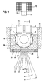
- FIG. 1 a partially illustrated valve in the form of a fuel injection valve with an embodiment of a multi-fan jet nozzle in a side view and schematically indicated liquid fins
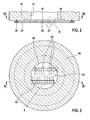
- FIG. 2 an off-center section through the valve end in the region of the multi-fan jet nozzle along the line II-II in FIG. 3,
- FIG. 3 a section through the valve end along the line III-III in FIG. 2 .
- FIG. 4 the detail IV off FIG. 2 with the large view of a slit-shaped injection opening in section
- FIG. 5 the detail V off FIG. 3 with the large view of a slot-shaped spray opening in plan view.
- FIG. 1 For example, as an embodiment, a valve in the form of an injector for fuel injection systems of mixture-compression spark-ignition internal combustion engines is partially shown.
- the fuel injection valve has a tubular valve seat carrier 1, which only schematically indicates a part of a valve housing and in which a longitudinal opening 3 is formed concentrically to a valve longitudinal axis 2.
- a longitudinal opening 3 In the longitudinal opening 3 is a z.
- the actuation of the fuel injection valve takes place in a known manner, for example electromagnetically.
- An actuation of the fuel injection valve with a piezoelectric or magnetostrictive actuator is also conceivable.
- a schematically indicated electromagnetic circuit with a solenoid 10, an armature 11 and a core 12.
- the armature 11 is connected to the valve closing body.
- 7 opposite end of the valve needle 5 is connected by, for example, a trained by a laser weld and aligned with the core 12.
- valve seat body 16 In the downstream end of the valve seat carrier 1 is a valve seat body 16, e.g. tightly assembled by welding.
- a disk-shaped multi-fan jet nozzle 23 At the valve closing body 7 facing away from the lower end face 17 of the valve seat body 16, a disk-shaped multi-fan jet nozzle 23 according to the invention is attached as an atomizer.
- the connection of valve seat body 16 and multi-fan jet nozzle 23 is effected for example by a circumferential and dense, formed by a laser weld 26, which, for. is provided on the end face 17 or on the outer periphery of valve seat body 16 and multi-fan jet nozzle 23.
- the attachment of the multi-fan jet nozzle 23 takes place in each case so that a central nozzle region 28 of the multi-fan jet nozzle 23 with a plurality of very small slot-shaped spray orifices 25 remains without negative deformation influences.
- an outlet opening 27 is provided, from which the fuel to be sprayed enters directly into the nozzle region 28 of the multi-fan jet nozzle 23.
- the multi-fan jet nozzle 23 is, for example, flat and lies flat on the end face 17 of the valve seat body 16.
- the formation of the nozzle portion 28 is above all in the FIGS. 2 to 5 clear. Due to the inventive design of the ejection orifices 25 in a specific slot shape and their distribution over the nozzle portion 28 of the multi-fan jet nozzle 23 liquid lamellae 30, wherein the individual liquid lamellae 30 move divergently to each other and in FIG. 1 are indicated only schematically.
- the closest to the center of the multi-fan jet nozzle 23 liquid lamella 30 has the smallest angle ⁇ to the central axis of the multi-fan jet nozzle 23 and here correspondingly also to the valve longitudinal axis 2, while the farthest from the center of the multi-fan jet nozzle 23 liquid lamella 30 largest angle, here ⁇ , to the central axis of the multi-fan jet nozzle 23 and the valve longitudinal axis 2 has. It therefore holds ⁇ ⁇ ⁇ ⁇ , etc.
- FIG. 2 shows an off-center section through the valve end in the region of the multi-fan jet nozzle 23 along the line II-II in FIG. 3
- FIG. 3 a section through the valve end along the line III-III in FIG. 2 shows.
- FIGS. 4 and 5 the details are IV and V off FIG. 2 respectively.
- FIG. 3 with large representations of a slot-shaped spray opening 25 in section and in plan view. From these figures, it is clear that each ejection opening 25 has a specific opening contour, with certain criteria for dimensioning and design in all ejection openings 25 recur.
- at least one inflow channel 40 in FIG.
- the inflow channels 40 extend.
- the two-stage injection openings 25 each have an inlet region 41 and an outlet region 42, which are, for example, rectangular.
- the ejection openings 25 are characterized by these two regions 41, 42, of which the inlet region 41 serves as a flow cavity and in particular the outlet region 42 extends in the form of a slot. Both the inlet region 41 and the outlet region 42 of the spray openings 25 extend at an angle, in particular at right angles to the upper inflow passage 40.
- the slot-shaped outlet region 42 of each spray opening 25 is always smaller in width than the upstream inlet region 41 of the respective spray opening 25, see FIG the entry region 41 always covers the exit region 42 from its base surface.
- the lengths of inlet region 41 and outlet region 42 do not necessarily have to be the same.
- the exact position of the outlet region 42 to the respective inlet region 41 is defined in each case and can vary from spray orifice 25 to spray orifice 25, as shown in FIG FIG. 3 is shown.
- the outlet region 42 With respect to the inlet region 41, moves ever further outward over all ejection openings 25.
- the two-layer ejection openings 25 have a greater length than the width of the inflow channel 40, so that effectively a fanning of the fuel and thus in each case a desired fan jet is achieved.
- FIG. 5 an ideal arrangement of inlet region 41 and outlet region 42 of the ejection opening 25 is shown.
- the exit region 42 of the injection orifice 25 may extend asymmetrically and / or contour-deviating and / or at an angle offset to the entry region 41.
- the inflow passage 40 may extend to the ejection openings 25 eccentrically overlapping.
- a flow asymmetry is introduced into the underlying inlet region 41, which leads to a tilting in the direction of the longitudinal extent of the spray-discharge openings 25 when the fan jet exits.
- This tilt angle should be set identically for all fan beams of a row of slots.
- the asymmetry may be generated identically to the first row of slots ( FIG. 3 ) or deviating from it. If the asymmetries of two rows of slots chosen opposite, the two fan beam rows are also perpendicular to the plane of the FIG. 1 hosed divergent to each other, resulting in a total of double divergence.
- the individual ejection openings 25 are aligned differently with respect to one another due to the different position of inlet region 41 and outlet region 42.
- the individual spray openings 25 are according to the embodiment of FIG. 3 arranged in two straight, parallel rows.
- the individual ejection openings 25 of a row that is to say an inflow channel 40, are placed precisely laterally offset in relation to the ejection openings 25 of the other inflow channel 40.
- liquid fins 30 can be produced, which spatially form lamellae packages in which the individual liquid fins 30 are sprayed divergently spread apart.
- the innermost liquid fin 30 has the smallest angle ⁇ to the central axis of the multi-fan jet nozzle 23 and the radially outermost liquid fin 30 the largest angle to the central axis of the multi-fan jet nozzle 23 ( ⁇ ⁇ ⁇ ⁇ , etc.).
- the divergence of the fan beams with the corresponding tilt achieved in this way ensures that the liquid fins 30 do not overlap in space.
- the slot-shaped spray openings 25 can be executed as a rectangle or slot, oval or curved curved.
- the outlet opening 27 of the valve seat body 16 may optionally be provided with a flow enlargement (Cavity 44) in order to guarantee the distribution of the flow over a wide area.
- a flow enlargement (Cavity 44) in order to guarantee the distribution of the flow over a wide area.
- FIGS. 4 and 5 the streamlines are marked with.
- the multi-fan jet nozzle 23 operates on the flat nozzle principle.
- the inflow channels 40 which extend over a plurality of ejection openings 25 and thus supply many ejection openings 25 with fuel
- the ejection openings 40 need not necessarily be arranged in a row on the multi-fan jet nozzle 23, but can be distributed arbitrarily on it.
- the multi-fan jet nozzle 23 is e.g. built by galvanic deposition (multilayer electroplating). On the other hand, however, it is likewise conceivable to produce the multi-fan jet nozzle 23 by stamping and embossing technology, by eroding technology or by etching.
- the atomization quality of the fan jet or of the lamellar decay is so high that fuel sprays with extremely small fuel droplets with a Sauter Mean Diameter (SMD) of approx. 20 ⁇ m can be sprayed off.
- SMD Sauter Mean Diameter
Landscapes
- Engineering & Computer Science (AREA)
- Chemical & Material Sciences (AREA)
- Combustion & Propulsion (AREA)
- Mechanical Engineering (AREA)
- General Engineering & Computer Science (AREA)
- Physics & Mathematics (AREA)
- Electromagnetism (AREA)
- Fuel-Injection Apparatus (AREA)
Applications Claiming Priority (1)
| Application Number | Priority Date | Filing Date | Title |
|---|---|---|---|
| DE200710062187 DE102007062187A1 (de) | 2007-12-21 | 2007-12-21 | Brennstoffeinspritzventil |
Publications (2)
| Publication Number | Publication Date |
|---|---|
| EP2072798A2 true EP2072798A2 (fr) | 2009-06-24 |
| EP2072798A3 EP2072798A3 (fr) | 2009-11-04 |
Family
ID=40433794
Family Applications (1)
| Application Number | Title | Priority Date | Filing Date |
|---|---|---|---|
| EP08105634A Withdrawn EP2072798A3 (fr) | 2007-12-21 | 2008-10-23 | Soupape d'injection de carburant |
Country Status (2)
| Country | Link |
|---|---|
| EP (1) | EP2072798A3 (fr) |
| DE (1) | DE102007062187A1 (fr) |
Citations (3)
| Publication number | Priority date | Publication date | Assignee | Title |
|---|---|---|---|---|
| DE19636396A1 (de) | 1996-09-07 | 1998-03-12 | Bosch Gmbh Robert | Brennstoffeinspritzventil |
| DE19847625A1 (de) | 1997-10-17 | 1999-04-22 | Toyota Motor Co Ltd | Brennstoff-Einspritzventil |
| US6019296A (en) | 1997-11-19 | 2000-02-01 | Toyota Jidosha Kabushiki Kaisha | Fuel injector for an internal combustion engine |
Family Cites Families (3)
| Publication number | Priority date | Publication date | Assignee | Title |
|---|---|---|---|---|
| DE19607277A1 (de) * | 1995-03-29 | 1996-10-02 | Bosch Gmbh Robert | Lochscheibe, insbesondere für Einspritzventile |
| DE19639506A1 (de) * | 1996-09-26 | 1998-04-02 | Bosch Gmbh Robert | Lochscheibe und Ventil mit einer Lochscheibe |
| DE10059682A1 (de) * | 2000-12-01 | 2002-06-06 | Bosch Gmbh Robert | Zerstäuberscheibe und Brennstoffeinspritzventil mit einer Zerstäuberscheibe |
-
2007
- 2007-12-21 DE DE200710062187 patent/DE102007062187A1/de not_active Withdrawn
-
2008
- 2008-10-23 EP EP08105634A patent/EP2072798A3/fr not_active Withdrawn
Patent Citations (3)
| Publication number | Priority date | Publication date | Assignee | Title |
|---|---|---|---|---|
| DE19636396A1 (de) | 1996-09-07 | 1998-03-12 | Bosch Gmbh Robert | Brennstoffeinspritzventil |
| DE19847625A1 (de) | 1997-10-17 | 1999-04-22 | Toyota Motor Co Ltd | Brennstoff-Einspritzventil |
| US6019296A (en) | 1997-11-19 | 2000-02-01 | Toyota Jidosha Kabushiki Kaisha | Fuel injector for an internal combustion engine |
Also Published As
| Publication number | Publication date |
|---|---|
| EP2072798A3 (fr) | 2009-11-04 |
| DE102007062187A1 (de) | 2009-06-25 |
Similar Documents
| Publication | Publication Date | Title |
|---|---|---|
| EP1073838B1 (fr) | Soupape d'injection de carburant | |
| EP1184565B1 (fr) | Disque perforé notamment pour injecteurs et son procédé de fabrication | |
| DE19636396A1 (de) | Brennstoffeinspritzventil | |
| EP1836387B1 (fr) | Buse a jets multiples en eventail et soupape d'injection de carburant pourvue d'une telle buse | |
| EP1399669B1 (fr) | Soupape d'injection de carburant | |
| WO2008028786A1 (fr) | Soupape d'injection de combustible | |
| EP1402175B1 (fr) | Soupape d'injection de carburant | |
| DE102006041472A1 (de) | Brennstoffeinspritzventil | |
| WO2014183905A1 (fr) | Soupape de dosage d'un fluide | |
| EP1409867B1 (fr) | Soupape d'injection de carburant | |
| DE102006047136A1 (de) | Brennstoffeinspritzventil | |
| EP1379777B1 (fr) | Soupape d'injection de carburant | |
| DE102006041471A1 (de) | Brennstoffeinspritzventil | |
| DE102007062183A1 (de) | Brennstoffeinspritzventil | |
| DE102006041476A1 (de) | Brennstoffeinspritzventil | |
| DE102007062187A1 (de) | Brennstoffeinspritzventil | |
| EP2072805B1 (fr) | Soupape d'injection de combustible | |
| DE102007062189A1 (de) | Brennstoffeinspritzventil | |
| DE102004060535A1 (de) | Zerstäuberdüse | |
| DE102007062191A1 (de) | Brennstoffeinspritzventil | |
| DE102006044439A1 (de) | Brennstoffeinspritzventil | |
| DE102006041474A1 (de) | Brennstoffeinspritzventil | |
| DE102006044441A1 (de) | Brennstoffeinspritzventil | |
| DE10049519A1 (de) | Brennstoffeinspritzventil | |
| DE10118272A1 (de) | Brennstoffeinspritzventil |
Legal Events
| Date | Code | Title | Description |
|---|---|---|---|
| PUAI | Public reference made under article 153(3) epc to a published international application that has entered the european phase |
Free format text: ORIGINAL CODE: 0009012 |
|
| AK | Designated contracting states |
Kind code of ref document: A2 Designated state(s): AT BE BG CH CY CZ DE DK EE ES FI FR GB GR HR HU IE IS IT LI LT LU LV MC MT NL NO PL PT RO SE SI SK TR |
|
| AX | Request for extension of the european patent |
Extension state: AL BA MK RS |
|
| PUAL | Search report despatched |
Free format text: ORIGINAL CODE: 0009013 |
|
| AK | Designated contracting states |
Kind code of ref document: A3 Designated state(s): AT BE BG CH CY CZ DE DK EE ES FI FR GB GR HR HU IE IS IT LI LT LU LV MC MT NL NO PL PT RO SE SI SK TR |
|
| AX | Request for extension of the european patent |
Extension state: AL BA MK RS |
|
| 17P | Request for examination filed |
Effective date: 20100504 |
|
| 17Q | First examination report despatched |
Effective date: 20100610 |
|
| AKX | Designation fees paid |
Designated state(s): DE FR GB IT |
|
| GRAP | Despatch of communication of intention to grant a patent |
Free format text: ORIGINAL CODE: EPIDOSNIGR1 |
|
| STAA | Information on the status of an ep patent application or granted ep patent |
Free format text: STATUS: THE APPLICATION IS DEEMED TO BE WITHDRAWN |
|
| 18D | Application deemed to be withdrawn |
Effective date: 20130503 |