EP2072801A1 - Schwingungsdämpfende Hülse für Einspritzrohrbogen - Google Patents
Schwingungsdämpfende Hülse für Einspritzrohrbogen Download PDFInfo
- Publication number
- EP2072801A1 EP2072801A1 EP08305937A EP08305937A EP2072801A1 EP 2072801 A1 EP2072801 A1 EP 2072801A1 EP 08305937 A EP08305937 A EP 08305937A EP 08305937 A EP08305937 A EP 08305937A EP 2072801 A1 EP2072801 A1 EP 2072801A1
- Authority
- EP
- European Patent Office
- Prior art keywords
- noise reduction
- pipe
- injection pipe
- cylindrical
- reduction sleeve
- Prior art date
- Legal status (The legal status is an assumption and is not a legal conclusion. Google has not performed a legal analysis and makes no representation as to the accuracy of the status listed.)
- Granted
Links
- 238000002347 injection Methods 0.000 title claims abstract description 42
- 239000007924 injection Substances 0.000 title claims abstract description 42
- 238000010521 absorption reaction Methods 0.000 title 1
- 239000000463 material Substances 0.000 claims description 9
- 229920001971 elastomer Polymers 0.000 claims description 7
- 239000000806 elastomer Substances 0.000 claims description 4
- 229910000831 Steel Inorganic materials 0.000 claims description 3
- 239000010959 steel Substances 0.000 claims description 3
- 239000000243 solution Substances 0.000 description 10
- 238000012423 maintenance Methods 0.000 description 2
- 230000006978 adaptation Effects 0.000 description 1
- 238000005452 bending Methods 0.000 description 1
- 238000002485 combustion reaction Methods 0.000 description 1
- 230000000295 complement effect Effects 0.000 description 1
- 238000006073 displacement reaction Methods 0.000 description 1
- 230000000694 effects Effects 0.000 description 1
- 239000003344 environmental pollutant Substances 0.000 description 1
- 230000005284 excitation Effects 0.000 description 1
- 230000001939 inductive effect Effects 0.000 description 1
- 230000021715 photosynthesis, light harvesting Effects 0.000 description 1
- 231100000719 pollutant Toxicity 0.000 description 1
- 230000000284 resting effect Effects 0.000 description 1
- 230000001629 suppression Effects 0.000 description 1
Images


Classifications
-
- F—MECHANICAL ENGINEERING; LIGHTING; HEATING; WEAPONS; BLASTING
- F02—COMBUSTION ENGINES; HOT-GAS OR COMBUSTION-PRODUCT ENGINE PLANTS
- F02M—SUPPLYING COMBUSTION ENGINES IN GENERAL WITH COMBUSTIBLE MIXTURES OR CONSTITUENTS THEREOF
- F02M55/00—Fuel-injection apparatus characterised by their fuel conduits or their venting means; Arrangements of conduits between fuel tank and pump F02M37/00
-
- F—MECHANICAL ENGINEERING; LIGHTING; HEATING; WEAPONS; BLASTING
- F02—COMBUSTION ENGINES; HOT-GAS OR COMBUSTION-PRODUCT ENGINE PLANTS
- F02M—SUPPLYING COMBUSTION ENGINES IN GENERAL WITH COMBUSTIBLE MIXTURES OR CONSTITUENTS THEREOF
- F02M55/00—Fuel-injection apparatus characterised by their fuel conduits or their venting means; Arrangements of conduits between fuel tank and pump F02M37/00
- F02M55/02—Conduits between injection pumps and injectors, e.g. conduits between pump and common-rail or conduits between common-rail and injectors
-
- F—MECHANICAL ENGINEERING; LIGHTING; HEATING; WEAPONS; BLASTING
- F16—ENGINEERING ELEMENTS AND UNITS; GENERAL MEASURES FOR PRODUCING AND MAINTAINING EFFECTIVE FUNCTIONING OF MACHINES OR INSTALLATIONS; THERMAL INSULATION IN GENERAL
- F16L—PIPES; JOINTS OR FITTINGS FOR PIPES; SUPPORTS FOR PIPES, CABLES OR PROTECTIVE TUBING; MEANS FOR THERMAL INSULATION IN GENERAL
- F16L55/00—Devices or appurtenances for use in, or in connection with, pipes or pipe systems
- F16L55/02—Energy absorbers; Noise absorbers
- F16L55/033—Noise absorbers
- F16L55/0335—Noise absorbers by means of external rings
-
- F—MECHANICAL ENGINEERING; LIGHTING; HEATING; WEAPONS; BLASTING
- F02—COMBUSTION ENGINES; HOT-GAS OR COMBUSTION-PRODUCT ENGINE PLANTS
- F02M—SUPPLYING COMBUSTION ENGINES IN GENERAL WITH COMBUSTIBLE MIXTURES OR CONSTITUENTS THEREOF
- F02M2200/00—Details of fuel-injection apparatus, not otherwise provided for
- F02M2200/09—Fuel-injection apparatus having means for reducing noise
-
- F—MECHANICAL ENGINEERING; LIGHTING; HEATING; WEAPONS; BLASTING
- F02—COMBUSTION ENGINES; HOT-GAS OR COMBUSTION-PRODUCT ENGINE PLANTS
- F02M—SUPPLYING COMBUSTION ENGINES IN GENERAL WITH COMBUSTIBLE MIXTURES OR CONSTITUENTS THEREOF
- F02M2200/00—Details of fuel-injection apparatus, not otherwise provided for
- F02M2200/31—Fuel-injection apparatus having hydraulic pressure fluctuations damping elements
-
- F—MECHANICAL ENGINEERING; LIGHTING; HEATING; WEAPONS; BLASTING
- F02—COMBUSTION ENGINES; HOT-GAS OR COMBUSTION-PRODUCT ENGINE PLANTS
- F02M—SUPPLYING COMBUSTION ENGINES IN GENERAL WITH COMBUSTIBLE MIXTURES OR CONSTITUENTS THEREOF
- F02M2200/00—Details of fuel-injection apparatus, not otherwise provided for
- F02M2200/80—Fuel injection apparatus manufacture, repair or assembly
- F02M2200/8023—Fuel injection apparatus manufacture, repair or assembly the assembly involving use of quick-acting mechanisms, e.g. clips
-
- F—MECHANICAL ENGINEERING; LIGHTING; HEATING; WEAPONS; BLASTING
- F02—COMBUSTION ENGINES; HOT-GAS OR COMBUSTION-PRODUCT ENGINE PLANTS
- F02M—SUPPLYING COMBUSTION ENGINES IN GENERAL WITH COMBUSTIBLE MIXTURES OR CONSTITUENTS THEREOF
- F02M2200/00—Details of fuel-injection apparatus, not otherwise provided for
- F02M2200/90—Selection of particular materials
- F02M2200/9015—Elastomeric or plastic materials
Definitions
- the present invention relates to a noise reduction sleeve of an injection device of a motor vehicle, and an injection device and a motor vehicle as such comprising such a sleeve.
- the document EP1754885 describes a mechanical solution allowing the reflection of waves and the cancellation of the waves at the origin of the noise by a phenomenon of interference with the new waves generated. This solution is relatively complex.
- EP1764501 describes a solution that relies on the decoupling of the injector and its adjacent parts like the cylinder head and the flange, to reduce the noise.
- the object of the invention is to provide a simplified injection device for motor vehicle engine in which the sounds of "pan flute" are deleted or reduced.
- the invention is based on a noise reduction sleeve emitted by a motor vehicle injection pipe, characterized in that it comprises at least two cylindrical portions slit by a narrow slot, for clipping on a injection pipe, interconnected by an intermediate portion having at least a narrow portion to allow its deformation and offer the monolithic sleeve the ability to fit on a bend of a pipe, in a configuration where the at least two parts cylindrical can be clipped on two non-aligned portions of a pipe.
- the noise reduction sleeve may comprise two cylindrical lateral parts symmetrically arranged around a central intermediate portion.
- the central portion may represent a truncated portion of the cylinder of the cylindrical side portions.
- the central portion may be a discontinuously reduced portion of the cylinder relative to the lateral cylindrical portions or a progressively reduced cylinder portion with respect to the lateral cylindrical portions.
- the intermediate portion may represent a truncated portion of the cylinder of the cylindrical portions and has at least one reduced portion extending less than a quarter of the circumference of the cylinder of the cylindrical portions.
- the noise reduction sleeve can be in an elastomer or rubber material or any other material having a high coefficient of friction with steel.
- It may have a length approximately equal to 30 millimeters or between 0.6 and 1 times the developed length of the elbow.
- cylindrical portions may have an outer diameter (De) approximately equal to 13 millimeters or between 2 and 2.1 times the inner diameter (Di), and an inner diameter (Di) approximately equal to 6 millimeters, or included between 0.9 and 1 times the outer diameter of the injection pipe.
- the invention also relates to an injection device for a motor vehicle comprising at least one injection pipe having at least one elbow, characterized in that it comprises at least one noise reduction sleeve mounted on the elbow, such that described above, and preferably extending over at least 60% of the length of the elbow.
- the invention also relates to a motor vehicle comprising an injection device for a motor vehicle comprising at least one injection pipe having at least one elbow, characterized in that it comprises at least one noise reduction sleeve as described previously mounted on the elbow.
- the concept of the invention consists in the dissipation of the vibratory energy of the pipe by friction of a split sleeve mounted on it at the level of at least one of these elbows.
- the sleeve is in a material of elastomer or rubber type or any other material having a high coefficient of friction with steel. Since the excitation at the origin of the "pan flute" noise is of low intensity, the dissipation of the vibratory energy by such a sleeve is sufficient to attenuate this noise.
- the Figures 1 and 2 have a noise reduction sleeve 1 according to a first embodiment of the invention. It comprises a structure corresponding to a cylinder portion. It comprises more exactly two lateral parts of the same dimensions 2, cylindrical in shape slotted by a slot 4 of small dimension, symmetrically arranged around a central portion 3.
- This central portion 3 is in the form of a smaller portion of the same cylinder as the side portions 2, appears as a truncation of the side portions 2. According to this embodiment, this central portion 3 extends over a portion of less than a quarter of the circumference of the cylinder 2. It is arranged in the upper part of the sleeve 1 symmetrically around a longitudinal and vertical median plane x, z.
- the sleeve is formed in one piece and comprises a continuous portion 5 in its upper part over its entire length.
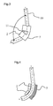
- FIGs 3 and 4 The use of this sleeve to reduce panflut sounds is illustrated in Figures 3 and 4 .
- the sleeve is positioned at a bend 11 of an injection pipe 10 of a motor vehicle engine. For this, the two parts around the slot 4 of each side portion 2 are spaced to let the pipe 10 which is housed in the central cylindrical portion 6 of the sleeve.
- the elasticity of the material used allows this establishment of the sleeve on the pipe through the slot 4 of small size. The elasticity of the material then allows it to resume its initial shape in which the two side portions 2 of the sleeve almost completely surround the pipe 10.
- the sleeve is installed on the pipe 10 by clipping in this manner alternately each of its lateral parts. 2 on the pipe 10.
- the central portion 3 is substantially resting on the pipe 10: however, it is bent in order to follow the curvature of the elbow 11 of the pipe and to allow each of the side portions 2 to conform to the circumference of two parts of the pipe 10 that are not aligned.
- the reduced dimensions of the central portion 3 of the sleeve as well as the material used allow it to have a deformable property and to connect two lateral parts in the form of two non-aligned portions of the pipe 10 at the elbow 11.
- the dimensions of the sleeve 1 are adapted to those of the pipe 10, so as to marry the better its surface and perform its function of dissipation of vibration energy.
- the sleeve 1 can form a partial cylinder with an outside diameter of about 13 millimeters and freeing an internal cylindrical space of diameter Di substantially equal to 6 millimeters intended to accommodate the injection pipe.
- it will comprise an outer diameter De of between 2 and 2.1 times the diameter of the internal space Di and an inner diameter Di of between 0.9 and 1 times the outside diameter of the injection pipe.
- the sleeve may have a total length L of about 30 millimeters, divided into three parts likewise length I of 10 millimeters for the two lateral parts 2 and the central part 3.
- the sleeve thus occupies generally almost the entire length of the elbow 11, extending almost to the straight portions on either side of the elbow 11. this, its length may advantageously be between 0.6 and 1.5 times the developed length of the elbow 11.
- the sleeve 1 thus positioned on a bend of the pipe 10, at the level of the maximum deformation zone of the pipe, itself undergoes a strong deformation.
- This has the advantage of inducing dissipation of the energy in two forms: first, a first portion of energy is dissipated by deformation of the elastomer and then a significant amount of energy is dissipated by friction between the sleeve and the high pressure hose.
- This strong energy dissipation leads to a strong reduction or even suppression of pipe noise type "pan flute". Most of this dissipation will occur naturally at the cylindrical portions 2 which almost completely surround the pipe.
- the central or intermediate portion between these cylindrical portions allows more particularly a good maintenance of the entire sleeve on the elbow and participates in the dissipation of energy by deformation.
- the solution also has the advantage of effective and durable maintenance of the sleeve on the pipe at the elbow. Indeed, the stressing necessary for bending the sleeve during its introduction induces a resultant force which then prevents any displacement of the sleeve.
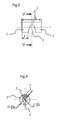
- FIG. 5 to 8 illustrate in this respect a second embodiment, in which the corresponding elements retain the same references, which differs in the shape of the central part 3.
- the figure 1 shows that the junction between the lateral portions 2 and the central portion 3 has a clear discontinuity, in a longitudinal vertical plane xz, to thereby form a square-shaped empty space 7 between the two lateral portions 2.
- the figure 5 shows that this junction is made by means of rounded shapes, which allow to obtain a central space 7 of rounded shape, half ovoid, between the two side portions 2.
- the central portion 3 and have a curvature equivalent to that of the first mode of execution at its central part, this curvature gradually increasing to reach almost the entire cylinder, with the exception of the slot 4, at the side portions 2.
- the two lateral parts are not necessarily symmetrical around a central part and the latter may have other shapes. It will have narrower dimensions representing a good compromise to give it a deformation property allowing the adaptation of the sleeve on elbows angle sometimes significant, while withstanding the stresses suffered due to repeated vibrations accumulated with its deformation on a bend .
- the sleeve will combine several cylindrical parts split by a narrow slot 4, intended for clipping on an injection pipe, interconnected by an intermediate portion having at least one narrow portion to allow its deformation and offer the monolithic sleeve the ability to fit on bends pipe.
- the concept of the invention is implemented as soon as at least one sleeve is positioned on a elbow of an injection pipe, marrying a non-rectilinear shape over a significant length of the elbow, to reduce the pan flute noise.
- the solution can be combined with one or more simplified sleeves mounted on a straight portion of an injection pipe. More generally, the invention remains compatible with other existing noise reduction solutions, which can be combined in a complementary manner.
Landscapes
- Engineering & Computer Science (AREA)
- General Engineering & Computer Science (AREA)
- Mechanical Engineering (AREA)
- Chemical & Material Sciences (AREA)
- Combustion & Propulsion (AREA)
- Fuel-Injection Apparatus (AREA)
- Pipe Accessories (AREA)
- Supports For Pipes And Cables (AREA)
- Exhaust Silencers (AREA)
- Vibration Prevention Devices (AREA)
- Joints Allowing Movement (AREA)
- Injection Moulding Of Plastics Or The Like (AREA)
Applications Claiming Priority (1)
| Application Number | Priority Date | Filing Date | Title |
|---|---|---|---|
| FR0708897A FR2925613B1 (fr) | 2007-12-19 | 2007-12-19 | Manchon d'absorption des vibrations pour un coude de tuyau d'injection |
Publications (2)
| Publication Number | Publication Date |
|---|---|
| EP2072801A1 true EP2072801A1 (de) | 2009-06-24 |
| EP2072801B1 EP2072801B1 (de) | 2011-11-02 |
Family
ID=39627847
Family Applications (1)
| Application Number | Title | Priority Date | Filing Date |
|---|---|---|---|
| EP08305937A Not-in-force EP2072801B1 (de) | 2007-12-19 | 2008-12-15 | Schwingungsdämpfende Hülse für Einspritzrohrbogen |
Country Status (4)
| Country | Link |
|---|---|
| EP (1) | EP2072801B1 (de) |
| AT (1) | ATE531930T1 (de) |
| ES (1) | ES2374187T3 (de) |
| FR (1) | FR2925613B1 (de) |
Cited By (5)
| Publication number | Priority date | Publication date | Assignee | Title |
|---|---|---|---|---|
| JP2012225476A (ja) * | 2011-04-22 | 2012-11-15 | Nippon Pop Rivets & Fasteners Ltd | 防振プロテクター |
| DE102013113925A1 (de) * | 2013-12-12 | 2015-06-18 | Dr. Ing. H.C. F. Porsche Aktiengesellschaft | Kraftstoffleitung |
| EP2899392A1 (de) * | 2014-01-23 | 2015-07-29 | Hans-Jürgen Guido | Nach dem Ferder-Masse-Prinzip arbeitender Schwingungstilger |
| CN106402501A (zh) * | 2016-11-09 | 2017-02-15 | 珠海格力电器股份有限公司 | 减振装置及具有其的空调器 |
| CN112901886A (zh) * | 2021-03-09 | 2021-06-04 | 江苏友奥电器有限公司 | 减震锤以及采用该减震锤的制冷设备 |
Citations (8)
| Publication number | Priority date | Publication date | Assignee | Title |
|---|---|---|---|---|
| EP0771992A1 (de) * | 1995-10-31 | 1997-05-07 | Groupement D'interet Economique Gazinox | Flexibler Metallschlauch mit einem aussen angebrachten schallvibrationsabsorbierenden Segment |
| JPH1030522A (ja) * | 1996-07-17 | 1998-02-03 | Denso Corp | 燃料噴射装置 |
| DE29803867U1 (de) * | 1998-03-05 | 1998-04-23 | DEUTZ AG, 51063 Köln | Geräuschminderung an Druckölleitungen |
| JP2002130077A (ja) * | 2000-10-25 | 2002-05-09 | Usui Internatl Ind Co Ltd | コモンレール式ディーゼルエンジン用燃料噴射管 |
| US20060005812A1 (en) | 2004-07-08 | 2006-01-12 | Toyota Jidosha Kabushiki Kaisha | Fuel injection control apparatus for internal combustion engine |
| EP1754885A1 (de) | 2005-08-19 | 2007-02-21 | Delphi Technologies, Inc. | Schalldämpfer für Kraftstoffeinspritzdüsengeräusche |
| EP1764501A1 (de) | 2005-09-15 | 2007-03-21 | Delphi Technologies, Inc. | Vorrichtung zur Befestigung eines Brennstoffeinspritzventils |
| US20070163545A1 (en) * | 2006-01-17 | 2007-07-19 | Beardmore John M | Isolated fuel delivery system |
-
2007
- 2007-12-19 FR FR0708897A patent/FR2925613B1/fr not_active Expired - Fee Related
-
2008
- 2008-12-15 EP EP08305937A patent/EP2072801B1/de not_active Not-in-force
- 2008-12-15 ES ES08305937T patent/ES2374187T3/es active Active
- 2008-12-15 AT AT08305937T patent/ATE531930T1/de active
Patent Citations (8)
| Publication number | Priority date | Publication date | Assignee | Title |
|---|---|---|---|---|
| EP0771992A1 (de) * | 1995-10-31 | 1997-05-07 | Groupement D'interet Economique Gazinox | Flexibler Metallschlauch mit einem aussen angebrachten schallvibrationsabsorbierenden Segment |
| JPH1030522A (ja) * | 1996-07-17 | 1998-02-03 | Denso Corp | 燃料噴射装置 |
| DE29803867U1 (de) * | 1998-03-05 | 1998-04-23 | DEUTZ AG, 51063 Köln | Geräuschminderung an Druckölleitungen |
| JP2002130077A (ja) * | 2000-10-25 | 2002-05-09 | Usui Internatl Ind Co Ltd | コモンレール式ディーゼルエンジン用燃料噴射管 |
| US20060005812A1 (en) | 2004-07-08 | 2006-01-12 | Toyota Jidosha Kabushiki Kaisha | Fuel injection control apparatus for internal combustion engine |
| EP1754885A1 (de) | 2005-08-19 | 2007-02-21 | Delphi Technologies, Inc. | Schalldämpfer für Kraftstoffeinspritzdüsengeräusche |
| EP1764501A1 (de) | 2005-09-15 | 2007-03-21 | Delphi Technologies, Inc. | Vorrichtung zur Befestigung eines Brennstoffeinspritzventils |
| US20070163545A1 (en) * | 2006-01-17 | 2007-07-19 | Beardmore John M | Isolated fuel delivery system |
Cited By (6)
| Publication number | Priority date | Publication date | Assignee | Title |
|---|---|---|---|---|
| JP2012225476A (ja) * | 2011-04-22 | 2012-11-15 | Nippon Pop Rivets & Fasteners Ltd | 防振プロテクター |
| DE102013113925A1 (de) * | 2013-12-12 | 2015-06-18 | Dr. Ing. H.C. F. Porsche Aktiengesellschaft | Kraftstoffleitung |
| EP2899392A1 (de) * | 2014-01-23 | 2015-07-29 | Hans-Jürgen Guido | Nach dem Ferder-Masse-Prinzip arbeitender Schwingungstilger |
| US10203060B2 (en) | 2014-01-23 | 2019-02-12 | Hans-Jurgen Guido | After the mass-spring principle operating vibration absorber |
| CN106402501A (zh) * | 2016-11-09 | 2017-02-15 | 珠海格力电器股份有限公司 | 减振装置及具有其的空调器 |
| CN112901886A (zh) * | 2021-03-09 | 2021-06-04 | 江苏友奥电器有限公司 | 减震锤以及采用该减震锤的制冷设备 |
Also Published As
| Publication number | Publication date |
|---|---|
| ATE531930T1 (de) | 2011-11-15 |
| FR2925613B1 (fr) | 2009-12-11 |
| ES2374187T3 (es) | 2012-02-14 |
| EP2072801B1 (de) | 2011-11-02 |
| FR2925613A1 (fr) | 2009-06-26 |
Similar Documents
| Publication | Publication Date | Title |
|---|---|---|
| CA2760290C (fr) | Cale d'aube de soufflante renforcee | |
| EP2072801B1 (de) | Schwingungsdämpfende Hülse für Einspritzrohrbogen | |
| EP2106943B1 (de) | Leitung mit einer Kraftfahrzeugklimaanlagekühlkreisgeräuschdämmungsvorrichtung, und Kühlkreis umfassend einer solchen Leitung | |
| FR3043732B1 (fr) | Rampe de carburant avec un amortissement de pulsations | |
| WO2008064970A1 (fr) | Barrette amortissant les vibrations de tuyaux d'injection sur un moteur a combustion interne | |
| EP1424472A2 (de) | Verbesserung zu einem flexibelen Entkopplungselement für eine Auspuffanlage eines Kraftfahrzeugmotors | |
| EP2836697A1 (de) | Kraftstoffeinspritzleiste für einen verbrennungsmotor | |
| EP3255262A1 (de) | Getriebelager, das als halterung für eine wasserpumpe in einer motorantriebsanlage dient | |
| FR2852060A1 (fr) | Repartiteur d'admission d'air pour moteur a combustion interne. | |
| FR2853942A1 (fr) | Dispositif de fixation d'ecran pour vehicule automobile | |
| FR2867252A1 (fr) | Dispositif de fixation par serrage de deux pieces | |
| FR2888615A1 (fr) | Fixation d'un element d'echappement sur le moteur | |
| FR2987098A1 (fr) | Tuyau de retour de fluide moteur et entree dans le carter | |
| FR2925651A1 (fr) | Manchon de reduction de bruit. | |
| EP2202431B1 (de) | Fuge eines Motorblocks, insbesondere für die Montage einer leicht starren Komponente auf diesen Motorblock | |
| EP2202432A1 (de) | Dichtung | |
| FR3021258A3 (fr) | Plot de suspension pour element de suspension d'une ligne d'echappement de vehicule automobile | |
| EP1653072B1 (de) | Schutzverkleidung einer Brennfraftmaschine | |
| FR3069888A1 (fr) | Silencieux pour ligne d'echappement de moteur thermique | |
| EP1795733A1 (de) | Schalldämpfer zur Verringerung von Luftgeräuschen, insbesondre für interne Brennkraftmaschinen | |
| FR2863659A1 (fr) | Dispositif d'obturation d'un conduit d'une ligne d'echappement | |
| FR3073918B1 (fr) | Dispositif anti-retour de fluide monobloc dans un aeronef et procede de fabrication d'un tel dispositif | |
| WO2022148587A1 (fr) | Protecteur acoustique à fixation rapide | |
| FR2919340A1 (fr) | Volume d'echappement d'une ligne d'echappement de vehicule automobile et procede de fabrication d'un tel volume d'echappement. | |
| FR2692205A1 (fr) | Dispositif d'articulation d'un triangle de suspension ou analogue sur la structure d'un véhicule automobile. |
Legal Events
| Date | Code | Title | Description |
|---|---|---|---|
| PUAI | Public reference made under article 153(3) epc to a published international application that has entered the european phase |
Free format text: ORIGINAL CODE: 0009012 |
|
| AK | Designated contracting states |
Kind code of ref document: A1 Designated state(s): AT BE BG CH CY CZ DE DK EE ES FI FR GB GR HR HU IE IS IT LI LT LU LV MC MT NL NO PL PT RO SE SI SK TR |
|
| AX | Request for extension of the european patent |
Extension state: AL BA MK RS |
|
| 17P | Request for examination filed |
Effective date: 20090730 |
|
| AKX | Designation fees paid |
Designated state(s): AT BE BG CH CY CZ DE DK EE ES FI FR GB GR HR HU IE IS IT LI LT LU LV MC MT NL NO PL PT RO SE SI SK TR |
|
| 17Q | First examination report despatched |
Effective date: 20100406 |
|
| GRAP | Despatch of communication of intention to grant a patent |
Free format text: ORIGINAL CODE: EPIDOSNIGR1 |
|
| GRAS | Grant fee paid |
Free format text: ORIGINAL CODE: EPIDOSNIGR3 |
|
| GRAA | (expected) grant |
Free format text: ORIGINAL CODE: 0009210 |
|
| AK | Designated contracting states |
Kind code of ref document: B1 Designated state(s): AT BE BG CH CY CZ DE DK EE ES FI FR GB GR HR HU IE IS IT LI LT LU LV MC MT NL NO PL PT RO SE SI SK TR |
|
| REG | Reference to a national code |
Ref country code: GB Ref legal event code: FG4D Free format text: NOT ENGLISH |
|
| RIN1 | Information on inventor provided before grant (corrected) |
Inventor name: PAQUIEN, MARC Inventor name: BOURACHOT, JEAN-LUC Inventor name: POURCEAU, JEAN-MICHEL |
|
| REG | Reference to a national code |
Ref country code: CH Ref legal event code: EP |
|
| REG | Reference to a national code |
Ref country code: IE Ref legal event code: FG4D |
|
| REG | Reference to a national code |
Ref country code: DE Ref legal event code: R096 Ref document number: 602008011055 Country of ref document: DE Effective date: 20111229 |
|
| REG | Reference to a national code |
Ref country code: ES Ref legal event code: FG2A Ref document number: 2374187 Country of ref document: ES Kind code of ref document: T3 Effective date: 20120214 |
|
| REG | Reference to a national code |
Ref country code: NL Ref legal event code: VDEP Effective date: 20111102 |
|
| LTIE | Lt: invalidation of european patent or patent extension |
Effective date: 20111102 |
|
| PG25 | Lapsed in a contracting state [announced via postgrant information from national office to epo] |
Ref country code: NO Free format text: LAPSE BECAUSE OF FAILURE TO SUBMIT A TRANSLATION OF THE DESCRIPTION OR TO PAY THE FEE WITHIN THE PRESCRIBED TIME-LIMIT Effective date: 20120202 Ref country code: LT Free format text: LAPSE BECAUSE OF FAILURE TO SUBMIT A TRANSLATION OF THE DESCRIPTION OR TO PAY THE FEE WITHIN THE PRESCRIBED TIME-LIMIT Effective date: 20111102 Ref country code: IS Free format text: LAPSE BECAUSE OF FAILURE TO SUBMIT A TRANSLATION OF THE DESCRIPTION OR TO PAY THE FEE WITHIN THE PRESCRIBED TIME-LIMIT Effective date: 20120302 |
|
| PG25 | Lapsed in a contracting state [announced via postgrant information from national office to epo] |
Ref country code: NL Free format text: LAPSE BECAUSE OF FAILURE TO SUBMIT A TRANSLATION OF THE DESCRIPTION OR TO PAY THE FEE WITHIN THE PRESCRIBED TIME-LIMIT Effective date: 20111102 Ref country code: PL Free format text: LAPSE BECAUSE OF FAILURE TO SUBMIT A TRANSLATION OF THE DESCRIPTION OR TO PAY THE FEE WITHIN THE PRESCRIBED TIME-LIMIT Effective date: 20111102 Ref country code: LV Free format text: LAPSE BECAUSE OF FAILURE TO SUBMIT A TRANSLATION OF THE DESCRIPTION OR TO PAY THE FEE WITHIN THE PRESCRIBED TIME-LIMIT Effective date: 20111102 Ref country code: PT Free format text: LAPSE BECAUSE OF FAILURE TO SUBMIT A TRANSLATION OF THE DESCRIPTION OR TO PAY THE FEE WITHIN THE PRESCRIBED TIME-LIMIT Effective date: 20120302 Ref country code: SE Free format text: LAPSE BECAUSE OF FAILURE TO SUBMIT A TRANSLATION OF THE DESCRIPTION OR TO PAY THE FEE WITHIN THE PRESCRIBED TIME-LIMIT Effective date: 20111102 Ref country code: SI Free format text: LAPSE BECAUSE OF FAILURE TO SUBMIT A TRANSLATION OF THE DESCRIPTION OR TO PAY THE FEE WITHIN THE PRESCRIBED TIME-LIMIT Effective date: 20111102 Ref country code: GR Free format text: LAPSE BECAUSE OF FAILURE TO SUBMIT A TRANSLATION OF THE DESCRIPTION OR TO PAY THE FEE WITHIN THE PRESCRIBED TIME-LIMIT Effective date: 20120203 Ref country code: HR Free format text: LAPSE BECAUSE OF FAILURE TO SUBMIT A TRANSLATION OF THE DESCRIPTION OR TO PAY THE FEE WITHIN THE PRESCRIBED TIME-LIMIT Effective date: 20111102 |
|
| REG | Reference to a national code |
Ref country code: IE Ref legal event code: FD4D |
|
| PG25 | Lapsed in a contracting state [announced via postgrant information from national office to epo] |
Ref country code: CY Free format text: LAPSE BECAUSE OF FAILURE TO SUBMIT A TRANSLATION OF THE DESCRIPTION OR TO PAY THE FEE WITHIN THE PRESCRIBED TIME-LIMIT Effective date: 20111102 |
|
| BERE | Be: lapsed |
Owner name: RENAULT S.A.S. Effective date: 20111231 |
|
| PG25 | Lapsed in a contracting state [announced via postgrant information from national office to epo] |
Ref country code: BG Free format text: LAPSE BECAUSE OF FAILURE TO SUBMIT A TRANSLATION OF THE DESCRIPTION OR TO PAY THE FEE WITHIN THE PRESCRIBED TIME-LIMIT Effective date: 20120202 Ref country code: CZ Free format text: LAPSE BECAUSE OF FAILURE TO SUBMIT A TRANSLATION OF THE DESCRIPTION OR TO PAY THE FEE WITHIN THE PRESCRIBED TIME-LIMIT Effective date: 20111102 Ref country code: SK Free format text: LAPSE BECAUSE OF FAILURE TO SUBMIT A TRANSLATION OF THE DESCRIPTION OR TO PAY THE FEE WITHIN THE PRESCRIBED TIME-LIMIT Effective date: 20111102 Ref country code: EE Free format text: LAPSE BECAUSE OF FAILURE TO SUBMIT A TRANSLATION OF THE DESCRIPTION OR TO PAY THE FEE WITHIN THE PRESCRIBED TIME-LIMIT Effective date: 20111102 Ref country code: IE Free format text: LAPSE BECAUSE OF FAILURE TO SUBMIT A TRANSLATION OF THE DESCRIPTION OR TO PAY THE FEE WITHIN THE PRESCRIBED TIME-LIMIT Effective date: 20111102 Ref country code: DK Free format text: LAPSE BECAUSE OF FAILURE TO SUBMIT A TRANSLATION OF THE DESCRIPTION OR TO PAY THE FEE WITHIN THE PRESCRIBED TIME-LIMIT Effective date: 20111102 Ref country code: MC Free format text: LAPSE BECAUSE OF NON-PAYMENT OF DUE FEES Effective date: 20111231 |
|
| PG25 | Lapsed in a contracting state [announced via postgrant information from national office to epo] |
Ref country code: RO Free format text: LAPSE BECAUSE OF FAILURE TO SUBMIT A TRANSLATION OF THE DESCRIPTION OR TO PAY THE FEE WITHIN THE PRESCRIBED TIME-LIMIT Effective date: 20111102 |
|
| PLBE | No opposition filed within time limit |
Free format text: ORIGINAL CODE: 0009261 |
|
| STAA | Information on the status of an ep patent application or granted ep patent |
Free format text: STATUS: NO OPPOSITION FILED WITHIN TIME LIMIT |
|
| REG | Reference to a national code |
Ref country code: AT Ref legal event code: MK05 Ref document number: 531930 Country of ref document: AT Kind code of ref document: T Effective date: 20111102 |
|
| 26N | No opposition filed |
Effective date: 20120803 |
|
| PG25 | Lapsed in a contracting state [announced via postgrant information from national office to epo] |
Ref country code: BE Free format text: LAPSE BECAUSE OF NON-PAYMENT OF DUE FEES Effective date: 20111231 |
|
| REG | Reference to a national code |
Ref country code: DE Ref legal event code: R097 Ref document number: 602008011055 Country of ref document: DE Effective date: 20120803 |
|
| PG25 | Lapsed in a contracting state [announced via postgrant information from national office to epo] |
Ref country code: AT Free format text: LAPSE BECAUSE OF FAILURE TO SUBMIT A TRANSLATION OF THE DESCRIPTION OR TO PAY THE FEE WITHIN THE PRESCRIBED TIME-LIMIT Effective date: 20111102 |
|
| PG25 | Lapsed in a contracting state [announced via postgrant information from national office to epo] |
Ref country code: MT Free format text: LAPSE BECAUSE OF FAILURE TO SUBMIT A TRANSLATION OF THE DESCRIPTION OR TO PAY THE FEE WITHIN THE PRESCRIBED TIME-LIMIT Effective date: 20111102 |
|
| PG25 | Lapsed in a contracting state [announced via postgrant information from national office to epo] |
Ref country code: LU Free format text: LAPSE BECAUSE OF NON-PAYMENT OF DUE FEES Effective date: 20111215 |
|
| PG25 | Lapsed in a contracting state [announced via postgrant information from national office to epo] |
Ref country code: FI Free format text: LAPSE BECAUSE OF FAILURE TO SUBMIT A TRANSLATION OF THE DESCRIPTION OR TO PAY THE FEE WITHIN THE PRESCRIBED TIME-LIMIT Effective date: 20111102 |
|
| REG | Reference to a national code |
Ref country code: CH Ref legal event code: PL |
|
| PG25 | Lapsed in a contracting state [announced via postgrant information from national office to epo] |
Ref country code: TR Free format text: LAPSE BECAUSE OF FAILURE TO SUBMIT A TRANSLATION OF THE DESCRIPTION OR TO PAY THE FEE WITHIN THE PRESCRIBED TIME-LIMIT Effective date: 20111102 |
|
| PG25 | Lapsed in a contracting state [announced via postgrant information from national office to epo] |
Ref country code: CH Free format text: LAPSE BECAUSE OF NON-PAYMENT OF DUE FEES Effective date: 20121231 Ref country code: HU Free format text: LAPSE BECAUSE OF FAILURE TO SUBMIT A TRANSLATION OF THE DESCRIPTION OR TO PAY THE FEE WITHIN THE PRESCRIBED TIME-LIMIT Effective date: 20111102 Ref country code: LI Free format text: LAPSE BECAUSE OF NON-PAYMENT OF DUE FEES Effective date: 20121231 |
|
| REG | Reference to a national code |
Ref country code: FR Ref legal event code: PLFP Year of fee payment: 8 |
|
| PGFP | Annual fee paid to national office [announced via postgrant information from national office to epo] |
Ref country code: DE Payment date: 20151211 Year of fee payment: 8 Ref country code: GB Payment date: 20151221 Year of fee payment: 8 |
|
| PGFP | Annual fee paid to national office [announced via postgrant information from national office to epo] |
Ref country code: ES Payment date: 20151214 Year of fee payment: 8 Ref country code: FR Payment date: 20151221 Year of fee payment: 8 |
|
| PGFP | Annual fee paid to national office [announced via postgrant information from national office to epo] |
Ref country code: IT Payment date: 20151228 Year of fee payment: 8 |
|
| REG | Reference to a national code |
Ref country code: DE Ref legal event code: R119 Ref document number: 602008011055 Country of ref document: DE |
|
| GBPC | Gb: european patent ceased through non-payment of renewal fee |
Effective date: 20161215 |
|
| REG | Reference to a national code |
Ref country code: FR Ref legal event code: ST Effective date: 20170831 |
|
| PG25 | Lapsed in a contracting state [announced via postgrant information from national office to epo] |
Ref country code: FR Free format text: LAPSE BECAUSE OF NON-PAYMENT OF DUE FEES Effective date: 20170102 Ref country code: IT Free format text: LAPSE BECAUSE OF NON-PAYMENT OF DUE FEES Effective date: 20161215 |
|
| PG25 | Lapsed in a contracting state [announced via postgrant information from national office to epo] |
Ref country code: DE Free format text: LAPSE BECAUSE OF NON-PAYMENT OF DUE FEES Effective date: 20170701 Ref country code: GB Free format text: LAPSE BECAUSE OF NON-PAYMENT OF DUE FEES Effective date: 20161215 |
|
| PG25 | Lapsed in a contracting state [announced via postgrant information from national office to epo] |
Ref country code: ES Free format text: LAPSE BECAUSE OF NON-PAYMENT OF DUE FEES Effective date: 20161216 |
|
| REG | Reference to a national code |
Ref country code: ES Ref legal event code: FD2A Effective date: 20181116 |