EP2072823B1 - Pompe centrifuge dotée d'une déaération - Google Patents
Pompe centrifuge dotée d'une déaération Download PDFInfo
- Publication number
- EP2072823B1 EP2072823B1 EP08021509.8A EP08021509A EP2072823B1 EP 2072823 B1 EP2072823 B1 EP 2072823B1 EP 08021509 A EP08021509 A EP 08021509A EP 2072823 B1 EP2072823 B1 EP 2072823B1
- Authority
- EP
- European Patent Office
- Prior art keywords
- separation chamber
- pump
- chamber
- venting
- pump according
- Prior art date
- Legal status (The legal status is an assumption and is not a legal conclusion. Google has not performed a legal analysis and makes no representation as to the accuracy of the status listed.)
- Active
Links
Images

Classifications
-
- F—MECHANICAL ENGINEERING; LIGHTING; HEATING; WEAPONS; BLASTING
- F04—POSITIVE - DISPLACEMENT MACHINES FOR LIQUIDS; PUMPS FOR LIQUIDS OR ELASTIC FLUIDS
- F04D—NON-POSITIVE-DISPLACEMENT PUMPS
- F04D9/00—Priming; Preventing vapour lock
- F04D9/001—Preventing vapour lock
- F04D9/002—Preventing vapour lock by means in the very pump
- F04D9/003—Preventing vapour lock by means in the very pump separating and removing the vapour
Definitions
- the invention relates to a centrifugal pump with a flowed through by the liquid to be conveyed, arranged in the flow direction in front of the pump chamber separation chamber, wherein the separation chamber is formed substantially cylindrical with a vertical axis, to form a liquid cyclone in the separation chamber of the liquid inlet has a tangential orientation, and Separation chamber has an upper central vent.
- the object of the invention is to improve the separation chamber upstream of a centrifugal pump in such a way that with small external dimensions a high venting performance can be achieved.
- This object is achieved in that the upper vent of the separation chamber is surrounded by a tube which projects down into the separation chamber and that the separation chamber is connected to the pump chamber via a channel, the goes off the side of the separation chamber at the level of the tube and opens at the suction port of the pump impeller.
- a low volume of the separation chamber can be achieved with high venting performance, so that the overall external dimensions of the venting device and the pump are low. Also, a particularly early and safe separation of the gas bubbles is achieved from the liquid.
- the length of the tube is 1 ⁇ 4 to 1 ⁇ 2 of the height of the separation chamber, preferably at least the height of the entrance of the channel.
- the upper vent opening of the separation chamber leads to a ventilation chamber arranged above the separation chamber, wherein an automatic venting takes place.
- the upper venting chamber may have a float which can be dismantled upwards.
- the housing of the venting device in particular the separation chamber is integrally connected to the housing of the pump, so that the pump and the venting device form a unit is particularly advantageous.
- the liquid inlet of the separation chamber has at least one guide surface guiding the liquid and the liquid inlet of the separation chamber is arranged on its underside and stationary guide vanes have in particular a guide vane ring.
- a particularly stable cyclone is produced in the separation chamber and, moreover, the outer dimensions are reduced since a lateral inflow is not required.
- the inlet of the separation chamber is arranged on its underside and in this case forms the suction nozzle of the pump.
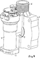
- a centrifugal pump 1 which is used in particular for circulating the heating water in heating systems, has within a pump housing 2 a spiral space 3, in which a pump impeller 1a is mounted.
- the pump impeller can be driven by an electric motor, not shown, which can be fastened with its motor housing to a connection surface 4 of the housing 2.
- a coaxial to the pump impeller 5 opens at the suction port of the pump impeller 1a, so that the pump 1 promotes from the channel 5 to the discharge nozzle 6, which is connected to the spiral space 3.
- the discharge nozzle 6 is arranged on the upper side of the pump with a preferably vertical axis and has an external thread 7.
- a ventilation device 8 is laterally formed with its housing 9, so that the two housings 2, 9 are in one piece.
- the housing 9 forms a lower separation chamber 10, in which the incoming liquid in particular water forms a cyclone, so that the space 10 can also be called a "cyclone chamber”.
- the separation chamber 10 has a lower liquid inlet 11, whose cross section is circular and corresponds to the cross section of the separation chamber 10. In this case, the inlet 11 goes down into the suction nozzle 12, which simultaneously forms the suction nozzle of the pump.
- a vane ring 13 is coaxially mounted near the lower liquid inlet 11 and thus close to the suction nozzle 12, wherein the guide vanes 14 annularly surround a central, aerodynamically shaped body.
- the guide vanes 14 move or rotate, but solely by the suction of the liquid is formed by the cyclone.
- the opening 16 is surrounded by a central coaxial tube 17, which is open at the bottom and thus projects down into the space 10 to safely receive the gas bubbles accumulating in the center of the cyclone and to lead upwards into a venting chamber 18.
- the length of the tube (17) 1 ⁇ 4 to 1 ⁇ 2 height of the separation chamber, preferably at least the height of the inlet 20 of the channel 5.
- a float 19 is mounted for automatic venting.
- the parts 11 to 19 are arranged coaxially to each other.
- the freed from the air bubbles liquid passes through an upper, arranged on the separation chamber 10 outlet opening 20 in a horizontal channel 5, which connects the separation chamber 10 with the spiral space 3, wherein the channel 5 opens at the suction opening of the pump impeller.
- the axis of the pressure port 6 is arranged parallel to the axis of the suction nozzle 12 and the separation chamber 10, so that a simple attachment in pipes is made possible.
Landscapes
- Engineering & Computer Science (AREA)
- Mechanical Engineering (AREA)
- General Engineering & Computer Science (AREA)
- Structures Of Non-Positive Displacement Pumps (AREA)
Claims (8)
- Pompe centrifuge (1) comprenant une chambre de séparation (10) parcourue par le liquide à refouler, disposée dans la direction d'écoulement avant la chambre de pompe (3),- la chambre de séparation (10) étant réalisée essentiellement sous forme cylindrique avec un axe vertical,- l'entrée de liquide, pour former un cyclone de liquide dans la chambre de séparation (10), présentant une orientation tangentielle, et- la chambre de séparation (10) présentant une ouverture de désaérage centrale supérieure (16),caractérisée en ce que l'ouverture de désaérage supérieure (16) de la chambre de séparation (10) est entourée par un tube (17) qui pénètre vers le bas dans la chambre de séparation (10) et en ce que la chambre de séparation (10) est connectée à l'espace de pompe (3) par le biais d'un canal (5) qui part latéralement de la chambre de séparation à la hauteur du tube (17) et qui débouche au niveau de l'ouverture d'aspiration du rotor de pompe.
- Pompe selon la revendication 1, caractérisée en ce que la longueur du tube (17) représente un quart à la moitié de la hauteur de la chambre de séparation (10), de préférence au moins la hauteur de l'entrée (20) du canal (5).
- Pompe selon l'une quelconque des revendications précédentes, caractérisée en ce que l'entrée (11) de la chambre de séparation (10) forme la tubulure d'aspiration (12) de la pompe (1) ou est proche de la tubulure d'aspiration (12) de la pompe (1).
- Pompe selon l'une quelconque des revendications précédentes, caractérisée en ce que l'ouverture de désaérage supérieure (16) de la chambre de séparation (10) conduit à une chambre de désaérage (18) disposée au-dessus de la chambre de séparation.
- Pompe selon la revendication 4, caractérisée en ce que la chambre de désaérage supérieure (18) présente un flotteur (19) qui peut être démonté vers le haut.
- Pompe selon l'une quelconque des revendications précédentes, caractérisée en ce que le boîtier (9) du dispositif de désaérage notamment de la chambre de séparation (10) est connecté d'une seule pièce au boîtier (2) de la pompe (1).
- Pompe selon l'une quelconque des revendications précédentes, caractérisée en ce que l'entrée de liquide de la chambre de séparation (10) présente au moins une surface conductrice (14) conduisant le liquide.
- Pompe selon l'une quelconque des revendications précédentes, caractérisée en ce que l'entrée de liquide (11) de la chambre de séparation (10) est disposée au niveau de son côté inférieur et présente au moins une aube directrice fixe (14), en particulier une couronne d'aubes directrices (13) .
Applications Claiming Priority (1)
| Application Number | Priority Date | Filing Date | Title |
|---|---|---|---|
| DE200710061558 DE102007061558A1 (de) | 2007-12-18 | 2007-12-18 | Kreiselpumpe mit Entlüftung |
Publications (3)
| Publication Number | Publication Date |
|---|---|
| EP2072823A2 EP2072823A2 (fr) | 2009-06-24 |
| EP2072823A3 EP2072823A3 (fr) | 2014-06-25 |
| EP2072823B1 true EP2072823B1 (fr) | 2018-08-08 |
Family
ID=40210450
Family Applications (1)
| Application Number | Title | Priority Date | Filing Date |
|---|---|---|---|
| EP08021509.8A Active EP2072823B1 (fr) | 2007-12-18 | 2008-12-11 | Pompe centrifuge dotée d'une déaération |
Country Status (2)
| Country | Link |
|---|---|
| EP (1) | EP2072823B1 (fr) |
| DE (1) | DE102007061558A1 (fr) |
Families Citing this family (2)
| Publication number | Priority date | Publication date | Assignee | Title |
|---|---|---|---|---|
| CH710814A2 (de) * | 2015-03-03 | 2016-09-15 | Imi Hydronic Eng Switzerland Ag | Vorrichtung zur Entgasung einer Flüssigkeit. |
| CN114893393B (zh) * | 2022-04-21 | 2024-05-17 | 北京太阳宫燃气热电有限公司 | 一种燃气锅炉给水泵的排气装置 |
Family Cites Families (9)
| Publication number | Priority date | Publication date | Assignee | Title |
|---|---|---|---|---|
| NL6404199A (fr) * | 1964-04-17 | 1965-10-18 | ||
| DE1653725A1 (de) * | 1967-09-29 | 1972-01-13 | Hanning Elektro Werke | Umwaelzpumpe fuer Heizungsanlagen |
| DE3068606D1 (en) * | 1979-09-13 | 1984-08-23 | Vaillant Joh Gmbh & Co | Pump with degasser |
| SE420230C (sv) * | 1980-10-20 | 1987-11-16 | Sala International Ab | Anordning for pumpning av skummande vetskor |
| DE8102304U1 (de) * | 1981-01-30 | 1981-07-02 | Grundfos A/S, 8850 Bjerringbro | Pumpe mit typenschild |
| DE3109918C2 (de) * | 1981-03-14 | 1989-03-16 | Wilo-Werk Gmbh & Co Pumpen- Und Apparatebau, 4600 Dortmund | Flüssigkeitspumpe mit Gasabscheidekammer |
| DE3703434A1 (de) | 1987-02-05 | 1988-08-18 | Oplaender Wilo Werk Gmbh | Kreiselpumpe mit entlueftung |
| AT389236B (de) * | 1987-11-03 | 1989-11-10 | Trawoeger Werner | Abscheider |
| DE19743062A1 (de) | 1997-09-30 | 1999-04-01 | Wilo Gmbh | Vorrichtung zum Abscheiden von Luft |
-
2007
- 2007-12-18 DE DE200710061558 patent/DE102007061558A1/de not_active Withdrawn
-
2008
- 2008-12-11 EP EP08021509.8A patent/EP2072823B1/fr active Active
Also Published As
| Publication number | Publication date |
|---|---|
| EP2072823A3 (fr) | 2014-06-25 |
| DE102007061558A1 (de) | 2009-06-25 |
| EP2072823A2 (fr) | 2009-06-24 |
Similar Documents
| Publication | Publication Date | Title |
|---|---|---|
| DE69023699T2 (de) | Selbstansaugende Kreiselpumpe. | |
| WO2014187648A1 (fr) | Ensemble pompe centrifuge auto-amorçante à plusieurs étages | |
| DE102005031420B4 (de) | Kombinierte Tauch-/Flachabsaug-Rotationspumpe mit konzentrischer Laufradeintrittsöffnung | |
| DE3419305A1 (de) | Verfahren und vorrichtung zum vermindern des gasgehaltes einer fluessigkeit | |
| EP2677178A2 (fr) | Pompe | |
| DE19822704B4 (de) | Gasabscheidende Brauchwasser-Zirkulationspumpe | |
| DE102019202874A1 (de) | Dampfturbinenvorrichtung | |
| EP2429677B1 (fr) | Filtre | |
| DE3033450C2 (de) | Vorrichtung zur Abscheidung von Gas aus einer Flüssigkeit | |
| DE19717799C5 (de) | Baueinheit für eine Kompaktheizungsanlage | |
| EP3348804A1 (fr) | Réservoir de lubrifiant pour un système hydraulique | |
| DE2510422A1 (de) | Kreiselpumpe | |
| DE102010030987B4 (de) | Fluidfilter | |
| DE3813654A1 (de) | Umwaelzpumpe | |
| EP2072823A2 (fr) | Pompe centrifuge dotée d'une déaération | |
| WO2007110284A1 (fr) | Dispositif de separation pour la separation de particules | |
| EP2397698B1 (fr) | Dispositif d'acheminement | |
| EP1873399B1 (fr) | Dispositif de pompe centrifuge | |
| DE102011117996A1 (de) | Rotationspumpe mit Verstellkranz zur Höhenverstellung | |
| DE112019005806B4 (de) | Kraftstoffpumpenanordnung mit elektrischer Motorkraftstoffpumpe und fluidgetriebener Kraftstoffpumpe | |
| EP1273728A2 (fr) | Dispositif de levage d'eaux usées avec conduit d'aspiration situé en point bas | |
| DE9208801U1 (de) | Pumpenaggregat | |
| WO2013087692A1 (fr) | Unité de transport de carburant | |
| WO2003011774A1 (fr) | Aerateur pour cours d'eau | |
| EP2845635A1 (fr) | Ventilateur |
Legal Events
| Date | Code | Title | Description |
|---|---|---|---|
| PUAI | Public reference made under article 153(3) epc to a published international application that has entered the european phase |
Free format text: ORIGINAL CODE: 0009012 |
|
| AK | Designated contracting states |
Kind code of ref document: A2 Designated state(s): AT BE BG CH CY CZ DE DK EE ES FI FR GB GR HR HU IE IS IT LI LT LU LV MC MT NL NO PL PT RO SE SI SK TR |
|
| AX | Request for extension of the european patent |
Extension state: AL BA MK RS |
|
| PUAL | Search report despatched |
Free format text: ORIGINAL CODE: 0009013 |
|
| AK | Designated contracting states |
Kind code of ref document: A3 Designated state(s): AT BE BG CH CY CZ DE DK EE ES FI FR GB GR HR HU IE IS IT LI LT LU LV MC MT NL NO PL PT RO SE SI SK TR |
|
| AX | Request for extension of the european patent |
Extension state: AL BA MK RS |
|
| RIC1 | Information provided on ipc code assigned before grant |
Ipc: F04D 9/00 20060101AFI20140516BHEP |
|
| 17P | Request for examination filed |
Effective date: 20141016 |
|
| RBV | Designated contracting states (corrected) |
Designated state(s): AT BE BG CH CY CZ DE DK EE ES FI FR GB GR HR HU IE IS IT LI LT LU LV MC MT NL NO PL PT RO SE SI SK TR |
|
| AKX | Designation fees paid |
Designated state(s): DE FR GB IT |
|
| AXX | Extension fees paid |
Extension state: BA Extension state: AL Extension state: MK Extension state: RS |
|
| GRAP | Despatch of communication of intention to grant a patent |
Free format text: ORIGINAL CODE: EPIDOSNIGR1 |
|
| INTG | Intention to grant announced |
Effective date: 20180321 |
|
| RAP1 | Party data changed (applicant data changed or rights of an application transferred) |
Owner name: WILO SE |
|
| GRAS | Grant fee paid |
Free format text: ORIGINAL CODE: EPIDOSNIGR3 |
|
| GRAA | (expected) grant |
Free format text: ORIGINAL CODE: 0009210 |
|
| AK | Designated contracting states |
Kind code of ref document: B1 Designated state(s): DE FR GB IT |
|
| REG | Reference to a national code |
Ref country code: GB Ref legal event code: FG4D Free format text: NOT ENGLISH |
|
| REG | Reference to a national code |
Ref country code: DE Ref legal event code: R096 Ref document number: 502008016242 Country of ref document: DE |
|
| REG | Reference to a national code |
Ref country code: DE Ref legal event code: R097 Ref document number: 502008016242 Country of ref document: DE |
|
| PLBE | No opposition filed within time limit |
Free format text: ORIGINAL CODE: 0009261 |
|
| STAA | Information on the status of an ep patent application or granted ep patent |
Free format text: STATUS: NO OPPOSITION FILED WITHIN TIME LIMIT |
|
| 26N | No opposition filed |
Effective date: 20190509 |
|
| PGFP | Annual fee paid to national office [announced via postgrant information from national office to epo] |
Ref country code: IT Payment date: 20211117 Year of fee payment: 14 |
|
| P01 | Opt-out of the competence of the unified patent court (upc) registered |
Effective date: 20230615 |
|
| PGFP | Annual fee paid to national office [announced via postgrant information from national office to epo] |
Ref country code: GB Payment date: 20231121 Year of fee payment: 16 |
|
| PG25 | Lapsed in a contracting state [announced via postgrant information from national office to epo] |
Ref country code: IT Free format text: LAPSE BECAUSE OF NON-PAYMENT OF DUE FEES Effective date: 20221211 |
|
| REG | Reference to a national code |
Ref country code: DE Ref legal event code: R084 Ref document number: 502008016242 Country of ref document: DE |
|
| PGFP | Annual fee paid to national office [announced via postgrant information from national office to epo] |
Ref country code: FR Payment date: 20241121 Year of fee payment: 17 |
|
| GBPC | Gb: european patent ceased through non-payment of renewal fee |
Effective date: 20241211 |
|
| PG25 | Lapsed in a contracting state [announced via postgrant information from national office to epo] |
Ref country code: GB Free format text: LAPSE BECAUSE OF NON-PAYMENT OF DUE FEES Effective date: 20241211 |
|
| PGFP | Annual fee paid to national office [announced via postgrant information from national office to epo] |
Ref country code: DE Payment date: 20251126 Year of fee payment: 18 |