EP2072883A1 - Schmiersystem und Verfahren für Fahrzeuge, die mit einem Klingenelement versehen sind - Google Patents
Schmiersystem und Verfahren für Fahrzeuge, die mit einem Klingenelement versehen sind Download PDFInfo
- Publication number
- EP2072883A1 EP2072883A1 EP07150178A EP07150178A EP2072883A1 EP 2072883 A1 EP2072883 A1 EP 2072883A1 EP 07150178 A EP07150178 A EP 07150178A EP 07150178 A EP07150178 A EP 07150178A EP 2072883 A1 EP2072883 A1 EP 2072883A1
- Authority
- EP
- European Patent Office
- Prior art keywords
- pump
- lubricant
- lubrication system
- blade element
- lubrication
- Prior art date
- Legal status (The legal status is an assumption and is not a legal conclusion. Google has not performed a legal analysis and makes no representation as to the accuracy of the status listed.)
- Granted
Links
- 238000005461 lubrication Methods 0.000 title claims abstract description 72
- 238000000034 method Methods 0.000 title claims description 16
- 239000000314 lubricant Substances 0.000 claims abstract description 39
- 230000004044 response Effects 0.000 claims abstract description 3
- 238000006073 displacement reaction Methods 0.000 claims description 9
- 230000001050 lubricating effect Effects 0.000 claims description 4
- 230000000994 depressogenic effect Effects 0.000 claims description 3
- 230000003213 activating effect Effects 0.000 claims description 2
- 230000000977 initiatory effect Effects 0.000 claims 1
- 230000007246 mechanism Effects 0.000 description 4
- 238000010276 construction Methods 0.000 description 3
- 238000010586 diagram Methods 0.000 description 3
- 239000012535 impurity Substances 0.000 description 2
- 230000000670 limiting effect Effects 0.000 description 2
- 239000000463 material Substances 0.000 description 2
- 230000008569 process Effects 0.000 description 2
- 230000005355 Hall effect Effects 0.000 description 1
- 230000009471 action Effects 0.000 description 1
- 230000004913 activation Effects 0.000 description 1
- 230000009849 deactivation Effects 0.000 description 1
- 230000000881 depressing effect Effects 0.000 description 1
- 239000000428 dust Substances 0.000 description 1
- 230000000694 effects Effects 0.000 description 1
- 230000007613 environmental effect Effects 0.000 description 1
- 239000004519 grease Substances 0.000 description 1
- 238000005065 mining Methods 0.000 description 1
- 230000004048 modification Effects 0.000 description 1
- 238000012986 modification Methods 0.000 description 1
Images


Classifications
-
- F—MECHANICAL ENGINEERING; LIGHTING; HEATING; WEAPONS; BLASTING
- F16—ENGINEERING ELEMENTS AND UNITS; GENERAL MEASURES FOR PRODUCING AND MAINTAINING EFFECTIVE FUNCTIONING OF MACHINES OR INSTALLATIONS; THERMAL INSULATION IN GENERAL
- F16N—LUBRICATING
- F16N9/00—Arrangements for supplying oil or unspecified lubricant from a moving reservoir or the equivalent
- F16N9/02—Arrangements for supplying oil or unspecified lubricant from a moving reservoir or the equivalent with reservoir on or in a rotary member
-
- F—MECHANICAL ENGINEERING; LIGHTING; HEATING; WEAPONS; BLASTING
- F16—ENGINEERING ELEMENTS AND UNITS; GENERAL MEASURES FOR PRODUCING AND MAINTAINING EFFECTIVE FUNCTIONING OF MACHINES OR INSTALLATIONS; THERMAL INSULATION IN GENERAL
- F16N—LUBRICATING
- F16N7/00—Arrangements for supplying oil or unspecified lubricant from a stationary reservoir or the equivalent in or on the machine or member to be lubricated
- F16N7/38—Arrangements for supplying oil or unspecified lubricant from a stationary reservoir or the equivalent in or on the machine or member to be lubricated with a separate pump; Central lubrication systems
-
- F—MECHANICAL ENGINEERING; LIGHTING; HEATING; WEAPONS; BLASTING
- F16—ENGINEERING ELEMENTS AND UNITS; GENERAL MEASURES FOR PRODUCING AND MAINTAINING EFFECTIVE FUNCTIONING OF MACHINES OR INSTALLATIONS; THERMAL INSULATION IN GENERAL
- F16N—LUBRICATING
- F16N7/00—Arrangements for supplying oil or unspecified lubricant from a stationary reservoir or the equivalent in or on the machine or member to be lubricated
- F16N7/38—Arrangements for supplying oil or unspecified lubricant from a stationary reservoir or the equivalent in or on the machine or member to be lubricated with a separate pump; Central lubrication systems
- F16N7/385—Central lubrication systems
Definitions
- This patent disclosure relates generally to articulated trucks provided with movable elements that require frequent greasing and, more particularly, to lubrication of ejector blade elements during operation.
- the present disclosure relates generally to industrial machines, such as tipped articulated trucks, which may be designed to carry heavy loads in a carriage located at the rear of the vehicle.
- These articulated trucks may be operated substantially in road construction, mining fields, or in any other environment where it is necessary to move material from one location to another. Performance increases may be achieved when a moving element, for instance an ejector blade, is used in the unloading process to better control removal of the material from the carriage.
- An alternative known way of providing a lubricant to the moving parts of a movable blade element consists in using an electrically operated pump applying lubricant to the lubrication points via a network of hoses, the electric pump being fixed at a fixed point of the machine and the lubrication lines lying between fixed and mobile parts of the vehicle.
- the disclosure provides a lubrication system for a vehicle provided with a blade element, wherein the blade element of the vehicle may be movable between a first position and a second position, the lubrication system including a pump connected to a reservoir of lubricant and an actuation element acting on the pump, the actuation element being activated by the blade element when displaced between the first and the second position.
- the disclosure provides a method of lubricating a vehicle, wherein the vehicle includes a pump connected to a lubricant reservoir and an actuation element acting on the pump, the method including the steps of displacing a blade element between a first position and a second position and activating the actuation element by displacement of the blade element between the first and the second position.
- This disclosure relates to a lubrication system for a vehicle provided with a blade element, wherein the blade element of the vehicle is movable between a first position and a second position, the lubrication system including a pump connected to a reservoir of lubricant and an actuation element acting on the pump, the actuation element being activated by the blade element when displaced between the first and the second position.
- the pump may be a mechanical pump, for example fixed to the movable blade element and provided with a plunger element engaging with the actuation element when the blade element is proximate to the first position.
- the plunger element may be depressed by the actuation element during the movement of the blade element from the second position towards the first position so as to create a pressure inside the pump, which may be suitable to dispense a displacement of a lubricant into a distribution system to feed the lubricant to at least one lubrication point.
- the lubrication system may include a distribution block having an inlet for receiving the lubricant from the pump and a plurality of outlets for feeding the lubricant to respective lubrication points and may further include flexible pressure hoses detachably connected to the movable blade element and interconnecting the pump, the distribution block and the at least one lubrication point.
- the movable blade element may include a plurality of ducts formed thereon, accommodating the interconnecting flexible pressure hoses.
- the actuation element can be arranged at one side of an ejection carriage in a same longitudinal direction as the plunger element.
- the actuation element may be movably mounted at one side of the ejection carriage in the axial direction of the plunger element, so as to adjust the stroke of the plunger element.
- the pump may include means to increase or decrease its stroke so as to adjust the amount of the displacement of the lubricant.
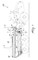
- the lubrication system is depicted as mounted on an industrial machine, such as a vehicle 100 provided with a blade element 1 movable between a first position 2 and a second position 3.
- the blade element 1 may be at least partially located inside an ejection carriage 35 and may be slideably mounted on rail elements 38 or similar guides mounted or present on the ejection carriage 35.
- the blade element moves in a direction that is substantially parallel to the bottom plane of the carriage 35, as indicated by double arrow 39.
- the lubrication system may comprise a pump 4 connected to a reservoir of lubricant 8 and an actuation element 6, for instance a striker, acting on the pump 4.
- the actuation element 6 may be activated in response to the blade element 1 being displaced from the second position 3 towards the first position 2, by direct engagement or indirect action.
- the first position 2 may be defined as the position at which the blade element 1 is fully retracted, i.e. the furthest position towards the driver's cabin of the vehicle 100 in the exemplary embodiment of Fig. 1 .
- the second position 3 may be defined as the position where the blade element 1 is fully extended, i.e. at the furthest end of the ejection carriage 35, as shown in Fig. 1 by the blade element represented in dashed lines at the rear end of the ejection carriage 35.
- the pump 4 may be preferably a mechanical pump, rigidly fixed to the movable blade element 1.
- the pump 4 may be fixed to a side wall 5 of the blade element 1, which is not exposed to the truckload.
- the pump 4 may be provided with a plunger element 7 that engages with the actuation element or striker 6 when the blade element 1 is proximate to the first position 2.
- the actuation element 6 and the plunger element 7 may be aligned on the same longitudinal axis so that their free ends face each other.
- the shape of the free end of the actuation element 6 is conical, but other shapes can be used and may vary in accordance with the shape and size of the free end of the plunger element 7 to be engaged.
- the actuation element 6 can be L-shaped, S-shaped or bow-shaped depending, for example, on the mounting position and, for example, to ensure that its free end faces the free end of the plunger element 7.
- the stroke of the plunger element 7 may be determined by the distance between the fully extended position when the plunger element 7 is not in contact with the actuation element 6, and the fully retracted position, when the position of the blade element 1 causes the actuation element 6 to engage with the plunger element 7. More in detail, at a certain time while the blade element 1 is retracted from the second position 3 towards the first position 2, the free end of the plunger element 7 may come into contact with the actuation element 6. The plunger element 7 may then be progressively depressed by the actuation element 6 during the movement of the blade element 1 which is still advancing from the second position 3 towards the first position 2 and creates pressure inside the pump 4.
- the pressure inside the pump 4 may be predetermined and suitable to dispense a displacement of a lubricant 8 into a distribution system 9 to feed the lubricant 8 to at least one lubrication point 10, 12, 14, 16, 18.
- the plunger element 7 may progressively release from the actuation element 6 until the two elements 6 and 7 are no longer in contact.
- the pump may include actuation means, which may be at least one sensor means of the electronic type.
- the at least one sensor means may be activated during the displacement of the blade element 1 between the second 3 and the first 2 position by sensor elements responding to electromagnetic irradiation, pressure changes or magnetic fields, or such.
- the sensor may transmit an electronic signal towards a processing unit adapted to actuate the pump 4 to release a lubricant.
- the duration of the signal actuating the pump may depend on the time between the sensor is activated and deactivated. It is also possible to predetermine the time inside the processing unit by using a known timer element.
- the at least one sensor means may be located on the rail elements 38, or on the bottom of the ejection carriage 35, which may be activated when the blade element's rollers, i.e. carriage and floor rollers, respectively, are moving from the second position 3 towards the first position 2.
- the activation and deactivation of the pump 4 may be obtained by interrupting the light passage of a photo sensor element, when the blade element 1 is entering the light path of the photo sensor.
- sensors detecting a magnetic field may be used, such as Hall-effect sensors, for actuation of the pump 4 when the blade element 1 moves from the second position 3 towards the first position 2.
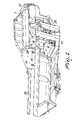
- Fig. 2 shows in more detail an ejection carriage 35 provided with a blade element 1 and an exemplary embodiment of the automatic lubrication system.
- the movable blade element 1 may be supported by two floor rollers when moving between the first 2 and the second 3 position.
- the floor rollers may have associated lubrication points 10, which may be interconnected to the pump 4 via a network of flexible pressure hoses 29, 30, 31.
- the hose pair 29 may feed a lubrication point 14 for a top rail roller and a lubrication point 15 of a side roller, the top rail roller and the side roller being associated with the blade element 1 on one of the two sides of the blade element 1.
- Respective lubrication points (not visible in the drawing) for a second top rail roller and a second side roller may be located on the opposite side of the blade element 1.
- the second top rail roller and the second side roller may be associated with the blade element 1 and may be interconnected by an additional hose pair 31.
- Another hose pair 30 may interconnect the pump 4 with a distribution block 22.
- the purpose of the distribution block 22 may be to centrally distribute the lubricant 8 received from the pump 4 to the respective destination lubrication points.
- a round-shaped element which may have two associated lubrication points 18, 19 for lubricating the hydraulic ram may be located in proximity to the hydraulic ram pushing the blade element 1.
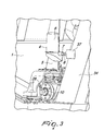
- Fig. 3 shows a more detailed view of the elements introduced in Fig.1 .
- the plunger element 7 is substantially round-shaped and is shown in Fig. 3 in an actuated position, i.e. in contact with a conical-shaped actuation element 6.
- the pump 4 may be mounted at a side wall 5 and may be fixed substantially perpendicular to the blade element 1.
- the actuation element 6 may be mounted by means of a plate 37 at one side 34 of the ejection carriage 35 in the same longitudinal direction as the plunger element 7.
- the actuation element 6 may be movably mounted at one side 34 of the ejection carriage 35 in the axial direction of the plunger element 7, so as to permit adjustment of the stroke of the plunger element 7 by adjusting the position of the actuation element 6.
- the pump 4 itself may include means to increase or decrease its stroke, so as to adjust the amount of the displacement of the lubricant 8.
- the means to increase or decrease the stroke of the pump may be for instance constituted by a slider mechanism attached to the side wall 5 on which the pump 4 can be detachably locked and fixed in certain positions along the sliding mechanism.
- both the actuation element 6 and the pump 4 can be movably mounted through slider mechanisms, one for the pump 4 and one for the actuation element 6, to detachably fix the pump 4 and/or the actuation element 6 in certain positions at appropriate mutual distance, in order to adjust the distance between them and, consequently, the stroke of the plunger element 7.
- Fig. 3 also shows a flexible pressure hose 28 adapted to feed a lubricant 8 to the lubrication point 10 of the floor roller, positioned below the pump 4.
- Fig. 4 and Fig. 5 which exemplify actuation of the pump 4 when the blade element 1 is being moved towards the first, retracted position 2.
- the plunger element 7 and the actuation element 6 are mutually spaced. No pressure is applied to the pump 4 and no lubricant is being released.
- the moving direction of the blade element 1 with the mounted pump 4 thereon is indicated by arrow 36, which points towards the actuation element 6.
- the actuation element 6 first contacts and then starts depressing the plunger element 7, until a fully retracted first position 2 is reached, as shown in Fig. 5 .
- the distribution system 9 may include a distribution block 22 having an inlet 23 for receiving the lubricant 8 from the pump 4 and a plurality of outlets 24, 25, 26, 27 for feeding the lubricant 8 to respective lubrication points 10, 12, 14, 16, 18.
- the lubrication points may include carriage rollers 14 and 16, floor rollers 10 and 12 and ejector cylinder mountings 18.
- the carriage rollers 14, 16 and the floor rollers 10, 12 may be pairs of rollers while the ejector cylinder mountings lubrication points 18 may be constituted by at least four lubrication points.
- the lubricant 8 may be driven through the flexible pressure hoses 29, 30, 31, 32, 33 when the automatic lubrication system is actuated.
- the flexible pressure hoses 29, 30, 31, 32, 33 may be detachably connected to the movable blade element 1 and may interconnect the pump 4, the distribution block 22 and the at least one lubrication point 10, 12, 14, 16, 18.
- the blade element 1 may include a plurality of ducts, not shown in the figures, formed thereon to accommodate the interconnecting flexible pressure hoses 29, 30, 31, 32, 33.
- the ducts may prevent the flexible pressure hoses from being damaged during operation of the vehicle 100 or by environmental influences.
- the above disclosed automatic lubrication system for an industrial machine may increase component reliability due to regular automatic lubrication, for example, every time the blade element moves into retracted position. This may enable the vehicle to be operated without interruption by the operator manually lubricating the lubrication points.
- the system may be easy to implement using common components, may be designed to be independent from any power supply, since it may be designed to be fully activated by mechanical elements, may be easy to upgrade, may be designed to assure uninterrupted operation, may be arranged to be easy and safe to maintain and may include features that may easily be adjusted with regard to the amount of grease to be released.
- the industrial applicability of the automatic lubrication system described herein will be readily appreciated from the foregoing discussion.
Landscapes
- Engineering & Computer Science (AREA)
- General Engineering & Computer Science (AREA)
- Mechanical Engineering (AREA)
- Details Of Reciprocating Pumps (AREA)
- Reciprocating Pumps (AREA)
- Structures Of Non-Positive Displacement Pumps (AREA)
Priority Applications (6)
| Application Number | Priority Date | Filing Date | Title |
|---|---|---|---|
| EP07150178.7A EP2072883B1 (de) | 2007-12-19 | 2007-12-19 | Schmiersystem und Verfahren für Fahrzeuge, die mit einem Klingenelement versehen sind |
| CN2008801218177A CN101903697A (zh) | 2007-12-19 | 2008-12-04 | 用于设有铲板元件的车辆的润滑系统和方法 |
| RU2010129526/06A RU2499178C2 (ru) | 2007-12-19 | 2008-12-04 | Система и способ смазки для транспортного средства, оснащенного ножевым элементом |
| PCT/EP2008/066782 WO2009080459A1 (en) | 2007-12-19 | 2008-12-04 | Lubrication system and method for vehicles provided with blade element |
| AU2008340541A AU2008340541A1 (en) | 2007-12-19 | 2008-12-04 | Lubrication system and method for vehicles provided with blade element |
| US12/808,710 US9169970B2 (en) | 2007-12-19 | 2008-12-04 | Lubrication system and method for vehicles provided with blade element |
Applications Claiming Priority (1)
| Application Number | Priority Date | Filing Date | Title |
|---|---|---|---|
| EP07150178.7A EP2072883B1 (de) | 2007-12-19 | 2007-12-19 | Schmiersystem und Verfahren für Fahrzeuge, die mit einem Klingenelement versehen sind |
Publications (2)
| Publication Number | Publication Date |
|---|---|
| EP2072883A1 true EP2072883A1 (de) | 2009-06-24 |
| EP2072883B1 EP2072883B1 (de) | 2016-04-27 |
Family
ID=39561894
Family Applications (1)
| Application Number | Title | Priority Date | Filing Date |
|---|---|---|---|
| EP07150178.7A Ceased EP2072883B1 (de) | 2007-12-19 | 2007-12-19 | Schmiersystem und Verfahren für Fahrzeuge, die mit einem Klingenelement versehen sind |
Country Status (6)
| Country | Link |
|---|---|
| US (1) | US9169970B2 (de) |
| EP (1) | EP2072883B1 (de) |
| CN (1) | CN101903697A (de) |
| AU (1) | AU2008340541A1 (de) |
| RU (1) | RU2499178C2 (de) |
| WO (1) | WO2009080459A1 (de) |
Families Citing this family (5)
| Publication number | Priority date | Publication date | Assignee | Title |
|---|---|---|---|---|
| WO2014168610A1 (en) * | 2013-04-09 | 2014-10-16 | Genesis Attachments, Llc | Slewing ring grease assembly |
| BR112016002329A2 (pt) * | 2013-08-07 | 2017-08-01 | Graco Minnesota Inc | sistema de lubrificação |
| KR102463856B1 (ko) * | 2017-03-30 | 2022-11-03 | 스미토모 겐키 가부시키가이샤 | 쇼벨 |
| US10760736B2 (en) | 2017-10-24 | 2020-09-01 | Deere & Company | Lubrication system and method for a work vehicle |
| US12276081B2 (en) * | 2022-06-06 | 2025-04-15 | Caterpillar Inc. | Lubrication distribution system for machine with kinematic linkages |
Citations (5)
| Publication number | Priority date | Publication date | Assignee | Title |
|---|---|---|---|---|
| US2870849A (en) * | 1956-09-12 | 1959-01-27 | Deere & Co | Automatic lubrication for disk harrows |
| US2996149A (en) * | 1959-11-16 | 1961-08-15 | Walker John | Lubricating systems |
| US3461990A (en) * | 1966-01-17 | 1969-08-19 | Tecalemit Engineering | Trailer lubrication systems |
| WO1998000629A1 (en) * | 1996-07-01 | 1998-01-08 | Gpx Corp. | Dipper door actuated lube pumping system |
| EP1514774A1 (de) * | 2003-09-09 | 2005-03-16 | Baier & Köppel GmbH & Co. | Sattelkupplung |
Family Cites Families (13)
| Publication number | Priority date | Publication date | Assignee | Title |
|---|---|---|---|---|
| JPS5569929U (de) * | 1978-11-10 | 1980-05-14 | ||
| DE3172590D1 (en) * | 1981-06-19 | 1985-11-14 | Sulzer Ag | Distributor element for a lubrication apparatus, more specifically for a loom |
| US4674030A (en) * | 1984-01-24 | 1987-06-16 | Bijur Lubricating Corp. | Lubricating system control circuit |
| US4930600A (en) * | 1988-11-21 | 1990-06-05 | Tranergy Corporation | Intelligent on-board rail lubrication system for curved and tangent track |
| FR2647182B1 (fr) * | 1989-05-22 | 1992-01-10 | Cit Alcatel | Dispositif pour l'alimentation en graisse de plusieurs paliers |
| SU1730483A1 (ru) * | 1990-03-16 | 1992-04-30 | Московский Научно-Производственное Объединение По Строительному И Дорожному Машиностроению | Шарнирное соединение |
| EP0612891A4 (en) * | 1991-11-06 | 1995-11-29 | Komatsu Mfg Co Ltd | Automatic greasing system for construction machines and abnormality detecting method therefor. |
| DE4241073C1 (de) * | 1992-12-05 | 1994-06-01 | Satzinger Gmbh & Co | Apparat für die dosierte Abgabe von einem Fluid, insbesondere von einem Schmiermittelfluid |
| US5417308A (en) * | 1993-08-09 | 1995-05-23 | Hartl; Toby L. | Trailer fifth wheel lubrication apparatus |
| US5381874A (en) * | 1993-10-15 | 1995-01-17 | Caterpillar Inc. | Automatic lubrication control |
| RU4759U1 (ru) * | 1996-04-18 | 1997-08-16 | Геннадий Борисович Фальковский | Ковш экскаватора |
| US6409121B1 (en) * | 2000-08-30 | 2002-06-25 | The Boeing Company | In flight autolubrication system for the mechanical members of aircraft landing gear |
| US7326023B2 (en) | 2002-02-25 | 2008-02-05 | Hagenbuch Leroy G | Rear eject body for off-highway haulage units |
-
2007
- 2007-12-19 EP EP07150178.7A patent/EP2072883B1/de not_active Ceased
-
2008
- 2008-12-04 AU AU2008340541A patent/AU2008340541A1/en not_active Abandoned
- 2008-12-04 RU RU2010129526/06A patent/RU2499178C2/ru not_active IP Right Cessation
- 2008-12-04 US US12/808,710 patent/US9169970B2/en active Active
- 2008-12-04 WO PCT/EP2008/066782 patent/WO2009080459A1/en not_active Ceased
- 2008-12-04 CN CN2008801218177A patent/CN101903697A/zh active Pending
Patent Citations (5)
| Publication number | Priority date | Publication date | Assignee | Title |
|---|---|---|---|---|
| US2870849A (en) * | 1956-09-12 | 1959-01-27 | Deere & Co | Automatic lubrication for disk harrows |
| US2996149A (en) * | 1959-11-16 | 1961-08-15 | Walker John | Lubricating systems |
| US3461990A (en) * | 1966-01-17 | 1969-08-19 | Tecalemit Engineering | Trailer lubrication systems |
| WO1998000629A1 (en) * | 1996-07-01 | 1998-01-08 | Gpx Corp. | Dipper door actuated lube pumping system |
| EP1514774A1 (de) * | 2003-09-09 | 2005-03-16 | Baier & Köppel GmbH & Co. | Sattelkupplung |
Also Published As
| Publication number | Publication date |
|---|---|
| CN101903697A (zh) | 2010-12-01 |
| EP2072883B1 (de) | 2016-04-27 |
| AU2008340541A1 (en) | 2009-07-02 |
| US20110017550A1 (en) | 2011-01-27 |
| US9169970B2 (en) | 2015-10-27 |
| RU2499178C2 (ru) | 2013-11-20 |
| WO2009080459A1 (en) | 2009-07-02 |
| RU2010129526A (ru) | 2012-01-27 |
Similar Documents
| Publication | Publication Date | Title |
|---|---|---|
| US9169970B2 (en) | Lubrication system and method for vehicles provided with blade element | |
| DE68917157T2 (de) | Einrichtung zur übertragung von energie. | |
| EP0389273A1 (de) | Bowdenzuganlage | |
| DE102018207202B4 (de) | Fahrerloses Transportfahrzeug und Verfahren zum Betreiben eines fahrerlosen Transportfahrzeugs | |
| EP3369696B1 (de) | Flurförderfahrzeug mit sensorkonzept sowie flurfördersystem | |
| CN103771102A (zh) | 地面输送线的正向积放装置 | |
| EP2818444A1 (de) | Mobile Arbeitsmaschine mit Bremsbetätigungsvorrichtung | |
| US9809950B2 (en) | Two stage moldboard rail cleaner | |
| EP3091125B1 (de) | Baumaschine mit einer hebevorrichtung für einen beschickungsvorgang und verfahren zum verstellen einer heckklappe | |
| US7681716B2 (en) | Work conveying apparatus, method for producing work and method for producing image forming apparatus | |
| EP2666743A1 (de) | Bremssystem mit einer Reinigungsvorrichtung | |
| EP3814264B1 (de) | Wartungsschalttafel und aufzugsteuerung zum steuern von verlagerungsbewegungen einer aufzugkabine | |
| EP3153348A1 (de) | Lastentransportfahrzeug mit überwachungsmitteln zur gesicherten handhabung eines wechselbehälters | |
| CN108526881A (zh) | 自动化随行配送系统及自动化生产线 | |
| CN108043663B (zh) | 一种汽车空调hvac零件涂油设备 | |
| EP2527534A1 (de) | Schubeinrichtung | |
| US6382383B1 (en) | Safety device for the control elements of a manually operated soil compaction roller | |
| CN211052435U (zh) | 一种油封链条自动装配设备及其定位滑块组件 | |
| CN120156850A (zh) | 物料输送系统和物料输送方法 | |
| EP3197733B1 (de) | Verfahren, parkbremssystem und fahrzeug zur parkbremskrafterzeugung | |
| KR20170054078A (ko) | 적재이송 작업기 및 이를 포함하는 적재이송장치 | |
| EP1529987A2 (de) | Rollnockenmechanismus und Antriebszusammensetzung mit positivem Rückzug | |
| DE102022117342A1 (de) | Flurförderzeug mit einer ersten Warnvorrichtung und einer zweiten Warnvorrichtung | |
| CN209974063U (zh) | 用于位置检测和限位的轿底与电梯 | |
| CN110143453B (zh) | 一种使用自动化装车装置的控制方法 |
Legal Events
| Date | Code | Title | Description |
|---|---|---|---|
| PUAI | Public reference made under article 153(3) epc to a published international application that has entered the european phase |
Free format text: ORIGINAL CODE: 0009012 |
|
| AK | Designated contracting states |
Kind code of ref document: A1 Designated state(s): AT BE BG CH CY CZ DE DK EE ES FI FR GB GR HU IE IS IT LI LT LU LV MC MT NL PL PT RO SE SI SK TR |
|
| AX | Request for extension of the european patent |
Extension state: AL BA HR MK RS |
|
| 17P | Request for examination filed |
Effective date: 20091119 |
|
| 17Q | First examination report despatched |
Effective date: 20100115 |
|
| AKX | Designation fees paid |
Designated state(s): DE GB |
|
| GRAP | Despatch of communication of intention to grant a patent |
Free format text: ORIGINAL CODE: EPIDOSNIGR1 |
|
| INTG | Intention to grant announced |
Effective date: 20151105 |
|
| GRAS | Grant fee paid |
Free format text: ORIGINAL CODE: EPIDOSNIGR3 |
|
| GRAA | (expected) grant |
Free format text: ORIGINAL CODE: 0009210 |
|
| AK | Designated contracting states |
Kind code of ref document: B1 Designated state(s): DE GB |
|
| REG | Reference to a national code |
Ref country code: GB Ref legal event code: FG4D |
|
| REG | Reference to a national code |
Ref country code: DE Ref legal event code: R096 Ref document number: 602007046011 Country of ref document: DE |
|
| REG | Reference to a national code |
Ref country code: DE Ref legal event code: R097 Ref document number: 602007046011 Country of ref document: DE |
|
| PGFP | Annual fee paid to national office [announced via postgrant information from national office to epo] |
Ref country code: GB Payment date: 20161125 Year of fee payment: 10 |
|
| PLBE | No opposition filed within time limit |
Free format text: ORIGINAL CODE: 0009261 |
|
| STAA | Information on the status of an ep patent application or granted ep patent |
Free format text: STATUS: NO OPPOSITION FILED WITHIN TIME LIMIT |
|
| 26N | No opposition filed |
Effective date: 20170130 |
|
| REG | Reference to a national code |
Ref country code: DE Ref legal event code: R119 Ref document number: 602007046011 Country of ref document: DE |
|
| PG25 | Lapsed in a contracting state [announced via postgrant information from national office to epo] |
Ref country code: DE Free format text: LAPSE BECAUSE OF NON-PAYMENT OF DUE FEES Effective date: 20170701 |
|
| GBPC | Gb: european patent ceased through non-payment of renewal fee |
Effective date: 20171219 |
|
| PG25 | Lapsed in a contracting state [announced via postgrant information from national office to epo] |
Ref country code: GB Free format text: LAPSE BECAUSE OF NON-PAYMENT OF DUE FEES Effective date: 20171219 |