EP2072890A2 - Lichtkörper mit einer Linse - Google Patents
Lichtkörper mit einer Linse Download PDFInfo
- Publication number
- EP2072890A2 EP2072890A2 EP08171853A EP08171853A EP2072890A2 EP 2072890 A2 EP2072890 A2 EP 2072890A2 EP 08171853 A EP08171853 A EP 08171853A EP 08171853 A EP08171853 A EP 08171853A EP 2072890 A2 EP2072890 A2 EP 2072890A2
- Authority
- EP
- European Patent Office
- Prior art keywords
- lens
- leds
- lighting body
- support
- opacified
- Prior art date
- Legal status (The legal status is an assumption and is not a legal conclusion. Google has not performed a legal analysis and makes no representation as to the accuracy of the status listed.)
- Withdrawn
Links
- 125000006850 spacer group Chemical group 0.000 claims description 4
- 230000000717 retained effect Effects 0.000 claims 1
- 230000000694 effects Effects 0.000 description 4
- 230000003071 parasitic effect Effects 0.000 description 4
- 238000009792 diffusion process Methods 0.000 description 2
- 239000011521 glass Substances 0.000 description 2
- 238000004519 manufacturing process Methods 0.000 description 2
- 238000005488 sandblasting Methods 0.000 description 2
- 239000012780 transparent material Substances 0.000 description 2
- 239000003086 colorant Substances 0.000 description 1
- 230000000295 complement effect Effects 0.000 description 1
- 230000003287 optical effect Effects 0.000 description 1
- 230000011664 signaling Effects 0.000 description 1
- 238000001228 spectrum Methods 0.000 description 1
Images


Classifications
-
- F—MECHANICAL ENGINEERING; LIGHTING; HEATING; WEAPONS; BLASTING
- F21—LIGHTING
- F21V—FUNCTIONAL FEATURES OR DETAILS OF LIGHTING DEVICES OR SYSTEMS THEREOF; STRUCTURAL COMBINATIONS OF LIGHTING DEVICES WITH OTHER ARTICLES, NOT OTHERWISE PROVIDED FOR
- F21V17/00—Fastening of component parts of lighting devices, e.g. shades, globes, refractors, reflectors, filters, screens, grids or protective cages
- F21V17/10—Fastening of component parts of lighting devices, e.g. shades, globes, refractors, reflectors, filters, screens, grids or protective cages characterised by specific fastening means or way of fastening
- F21V17/12—Fastening of component parts of lighting devices, e.g. shades, globes, refractors, reflectors, filters, screens, grids or protective cages characterised by specific fastening means or way of fastening by screwing
-
- F—MECHANICAL ENGINEERING; LIGHTING; HEATING; WEAPONS; BLASTING
- F21—LIGHTING
- F21K—NON-ELECTRIC LIGHT SOURCES USING LUMINESCENCE; LIGHT SOURCES USING ELECTROCHEMILUMINESCENCE; LIGHT SOURCES USING CHARGES OF COMBUSTIBLE MATERIAL; LIGHT SOURCES USING SEMICONDUCTOR DEVICES AS LIGHT-GENERATING ELEMENTS; LIGHT SOURCES NOT OTHERWISE PROVIDED FOR
- F21K9/00—Light sources using semiconductor devices as light-generating elements, e.g. using light-emitting diodes [LED] or lasers
- F21K9/60—Optical arrangements integrated in the light source, e.g. for improving the colour rendering index or the light extraction
- F21K9/69—Details of refractors forming part of the light source
-
- F—MECHANICAL ENGINEERING; LIGHTING; HEATING; WEAPONS; BLASTING
- F21—LIGHTING
- F21V—FUNCTIONAL FEATURES OR DETAILS OF LIGHTING DEVICES OR SYSTEMS THEREOF; STRUCTURAL COMBINATIONS OF LIGHTING DEVICES WITH OTHER ARTICLES, NOT OTHERWISE PROVIDED FOR
- F21V5/00—Refractors for light sources
- F21V5/04—Refractors for light sources of lens shape
-
- F—MECHANICAL ENGINEERING; LIGHTING; HEATING; WEAPONS; BLASTING
- F21—LIGHTING
- F21Y—INDEXING SCHEME ASSOCIATED WITH SUBCLASSES F21K, F21L, F21S and F21V, RELATING TO THE FORM OR THE KIND OF THE LIGHT SOURCES OR OF THE COLOUR OF THE LIGHT EMITTED
- F21Y2115/00—Light-generating elements of semiconductor light sources
- F21Y2115/10—Light-emitting diodes [LED]
Definitions
- the present patent relates to the sector of lighting equipment, both outdoor and indoor, and in particular concerns a new lighting body with lens for light-emitting diodes.
- LEDs Light Emitting Diodes
- LEDs provide a high luminosity at a low cost in terms of both consumption and production, maintaining a high level of efficiency and dependability.
- These LEDs consist substantially of diodes which, if polarised directly, emit visible light.
- LEDs are used widely for signalling on control panels and as pilot lights, or as transmitters for remote controls and optical fibres.
- the first LEDs produced were available only in the colour red. Subsequently LEDs were developed that emitted both yellow and green light. With the production of LEDs with blue light, it was possible to produce devices which, incorporating at least three LEDs, one red, one green and one blue, could generate any colour.
- LEDs do not emit large quantities of light, hence they are usually coupled with other LEDs so as to form a lighting body with greater overall luminosity.
- a big drawback of the above-mentioned lighting bodies is due to the fact that each LED projects a cone of light independent of the others which, when they overlap each other, cause an anomaly known as parasitic light, manifested by the creation of a series of less luminous lines along the edge of the light projected onto a wall.
- the effect of the parasitic light is furthermore aggravated when LEDs are used which emit light of different colours like white, green, red or yellow, or white only; the lens separates the luminous spectrum, creating the rainbow effect on the edges.
- diaphragms are used; however, the latter considerably reduce the overall luminosity of the lighting body.
- the object of the new lighting body with lens for light-emitting diodes is to eliminate the effect of the parasitic light, maintaining almost unchanged the overall light emitted by the new lighting body.
- the new lighting body in its main parts, comprises a support for housing two or more LEDs and at least one lens, suitable for favouring uniform diffusion of the light emitted by said LEDs and conveying it into a narrower field 50° - 120° with respect to the light emitted by the LED which covers a field of 180°.
- Said support comprises at least one electronic circuit, connecting said LEDs to one another and to the electrical supply, and one or more hooks, integral with said support, suitable for hooking and retaining said lens.
- Said lens positioned above said support, comprises at least one central convex body, made of transparent material, for example plastic or glass, provided with a substantially convex or flat lower surface and a convex upper surface.
- Said lower surface in the preferred flat solution, comprises at least one diffusing opacified portion obtained, for example, by sandblasting or photoengraving, so as to leave the central part of said lower surface transparent and non-treated.
- said LEDs are housed on said support, so that they are located in the portion of said diffusing opacified lower surface.
- said LEDs are geometrically arranged on a circumference, where the circumference of the inner edge of said crown passes over and through the median points of said LEDs.
- Lighting body provided with support, for housing two or more LEDs, comprising at least one lens positioned above said support, provided with substantially flat lower surface, and where part of said lower surface is diffusing and opacified right to the centre of the LED so that part of the light emitted by each LED crosses the diffusing opacified part of said lower surface.
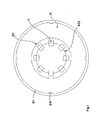
- Figure 1 shows an overhead view of the new lighting body, while figure 2 shows the lateral view of the new lighting body.
- Figure 3 shows a detail of the lens of the new lighting body.
- the new lighting body in its main parts, comprises a support (S) for housing at least eight LEDs (L) and at least one lens (A) suitable for favouring uniform diffusion of the light emitted by said LEDs (L).
- Said support (S), substantially cylindrical in shape, comprises at least one seat, located on the upper surface of said support (S), for housing at least one electronic circuit (C), at least one thread (F) on the lateral surface of said support (S), at least one spacer (D), substantially annular, suitable for supporting said lens (L), and at least one ring nut (S1) provided with at least four hooks (S11), integral with said ring nut (S1), suitable for hooking and retaining said lens (A).
- the dimensions of the inner edge (D1) of said spacer (D) are such that it does not overlap said LEDs.
- Said ring nut (S1) can be screw-tightened to said thread (F) of said support (S) in order to lock said lens (A).
- Said lens (A), positioned above said spacer (D), comprises at least one semi-spherical central body (A1) made of transparent material, for example plastic or glass, provided with substantially flat lower surface and semi-spherical upper surface (A4).
- Said flat lower surface comprises an outer diffusing crown (A2) opacified by means of sandblasting or photoengraving for plastic, for example, and a transparent non-treated central disc (A3).
- the dimensions of the inner edge (A21) of said outer crown (A2) are such that it overlaps said LEDs at least partly.
- said LEDs (L) are geometrically arranged on a circumference and the circumference of the inner edge (A21) of said crown (A2) passes over and through the median points of said LEDs (L).
- Said LEDs (L) are arranged radially on said support (S) so that their light crosses said lens (A) in the outer crown (A2).
Landscapes
- Engineering & Computer Science (AREA)
- General Engineering & Computer Science (AREA)
- Physics & Mathematics (AREA)
- Microelectronics & Electronic Packaging (AREA)
- Optics & Photonics (AREA)
- Non-Portable Lighting Devices Or Systems Thereof (AREA)
- Securing Globes, Refractors, Reflectors Or The Like (AREA)
Applications Claiming Priority (1)
| Application Number | Priority Date | Filing Date | Title |
|---|---|---|---|
| IT000426A ITPD20070426A1 (it) | 2007-12-21 | 2007-12-21 | Corpo illuminante con lente |
Publications (2)
| Publication Number | Publication Date |
|---|---|
| EP2072890A2 true EP2072890A2 (de) | 2009-06-24 |
| EP2072890A3 EP2072890A3 (de) | 2010-09-01 |
Family
ID=40315760
Family Applications (1)
| Application Number | Title | Priority Date | Filing Date |
|---|---|---|---|
| EP08171853A Withdrawn EP2072890A3 (de) | 2007-12-21 | 2008-12-16 | Lichtkörper mit einer Linse |
Country Status (2)
| Country | Link |
|---|---|
| EP (1) | EP2072890A3 (de) |
| IT (1) | ITPD20070426A1 (de) |
Cited By (5)
| Publication number | Priority date | Publication date | Assignee | Title |
|---|---|---|---|---|
| WO2011067096A1 (de) * | 2009-12-04 | 2011-06-09 | Osram Gesellschaft mit beschränkter Haftung | Leuchtmodul |
| WO2011067093A1 (de) * | 2009-12-04 | 2011-06-09 | Osram Gesellschaft mit beschränkter Haftung | Leuchtvorrichtung und aufsatzelement zur befestigung an der leuchtvorrichtung |
| ITTV20090240A1 (it) * | 2009-12-30 | 2011-06-30 | Rossano Zamengo | Faro e relativo metodo di assemblaggio |
| DE102011076613A1 (de) * | 2011-05-27 | 2012-11-29 | Osram Ag | LED-Leuchte |
| EP3136455A4 (de) * | 2014-04-22 | 2017-10-25 | Fernando Ruiz de Apodaca Cardeñosa | Optisches system für led-lampen und leuchten |
Family Cites Families (6)
| Publication number | Priority date | Publication date | Assignee | Title |
|---|---|---|---|---|
| DE19831004A1 (de) * | 1998-07-10 | 2000-02-03 | Volkswagen Ag | LED-Leuchte für ein Kraftfahrzeug |
| US6502956B1 (en) * | 1999-03-25 | 2003-01-07 | Leotek Electronics Corporation | Light emitting diode lamp with individual LED lenses |
| US6616299B2 (en) * | 2001-02-02 | 2003-09-09 | Gelcore Llc | Single optical element LED signal |
| JP4360945B2 (ja) * | 2004-03-10 | 2009-11-11 | シチズン電子株式会社 | 照明装置 |
| US20050286145A1 (en) * | 2004-06-25 | 2005-12-29 | Swarco Futurit Verkehrssignalsysteme Ges.M.B.H. | Invention concerning a condensor lens |
| US7196358B1 (en) * | 2005-11-25 | 2007-03-27 | Solidlite Corporation | Light emitting diode module with high heat dissipation |
-
2007
- 2007-12-21 IT IT000426A patent/ITPD20070426A1/it unknown
-
2008
- 2008-12-16 EP EP08171853A patent/EP2072890A3/de not_active Withdrawn
Cited By (11)
| Publication number | Priority date | Publication date | Assignee | Title |
|---|---|---|---|---|
| WO2011067096A1 (de) * | 2009-12-04 | 2011-06-09 | Osram Gesellschaft mit beschränkter Haftung | Leuchtmodul |
| WO2011067093A1 (de) * | 2009-12-04 | 2011-06-09 | Osram Gesellschaft mit beschränkter Haftung | Leuchtvorrichtung und aufsatzelement zur befestigung an der leuchtvorrichtung |
| CN102639931A (zh) * | 2009-12-04 | 2012-08-15 | 欧司朗股份有限公司 | 发光模块 |
| CN102639933A (zh) * | 2009-12-04 | 2012-08-15 | 欧司朗股份有限公司 | 照明装置和用于固定在该照明装置上的附连元件 |
| US8702274B2 (en) | 2009-12-04 | 2014-04-22 | Osram Gmbh | Lighting device and attachment element for fixing to the lighting device |
| CN102639933B (zh) * | 2009-12-04 | 2014-12-31 | 欧司朗股份有限公司 | 照明装置和用于固定在该照明装置上的附连元件 |
| CN102639931B (zh) * | 2009-12-04 | 2015-07-15 | 欧司朗股份有限公司 | 发光模块 |
| ITTV20090240A1 (it) * | 2009-12-30 | 2011-06-30 | Rossano Zamengo | Faro e relativo metodo di assemblaggio |
| DE102011076613A1 (de) * | 2011-05-27 | 2012-11-29 | Osram Ag | LED-Leuchte |
| DE102011076613B4 (de) | 2011-05-27 | 2022-10-20 | Siteco Gmbh | LED-Leuchte und Verfahren zur Herstellung der LED-Leuchte |
| EP3136455A4 (de) * | 2014-04-22 | 2017-10-25 | Fernando Ruiz de Apodaca Cardeñosa | Optisches system für led-lampen und leuchten |
Also Published As
| Publication number | Publication date |
|---|---|
| EP2072890A3 (de) | 2010-09-01 |
| ITPD20070426A1 (it) | 2009-06-22 |
Similar Documents
| Publication | Publication Date | Title |
|---|---|---|
| CN216591462U (zh) | 一种可放射射线图案灯具 | |
| EP3653924B1 (de) | Beleuchtungsvorrichtung | |
| US8083381B2 (en) | Holiday light with LED | |
| CN203190107U (zh) | 智能型可自动变换光的颜色的led灯具 | |
| EP2072890A2 (de) | Lichtkörper mit einer Linse | |
| CN206708826U (zh) | 一种可变色发光的led草坪灯 | |
| US11802673B2 (en) | Intelligent dimming RGB LED spotlight with high light quality and a method for achieving the same | |
| CN102072452A (zh) | 发光二极管灯具 | |
| CN203821195U (zh) | 一种led立体发光方形地砖 | |
| CN207065451U (zh) | 一种led灯管 | |
| CN201764372U (zh) | 一种低功率贴片式led交通信号灯发光装置 | |
| CN203190133U (zh) | 彩光照明灯具 | |
| CN2926787Y (zh) | 一种舞台灯 | |
| CN202266949U (zh) | 吸顶灯 | |
| CN205208331U (zh) | 改良的led吸顶灯 | |
| CN211450747U (zh) | 一种高光品质的智能调光rgb led射灯 | |
| CN210891473U (zh) | 一种反射式和直射式结合的灯具 | |
| CN103185280A (zh) | Led灯泡 | |
| CN210069647U (zh) | 手机app控制调温调亮灯 | |
| CN103185282A (zh) | Led灯泡 | |
| TW201326641A (zh) | Led燈泡 | |
| US20130235571A1 (en) | Recessed multicolored led lamp | |
| CN113932186A (zh) | 一种可更换灯珠的旋转式立体led灯 | |
| WO2017114429A1 (zh) | 一种led光源装置 | |
| CN206504210U (zh) | 一种盘状led光源 |
Legal Events
| Date | Code | Title | Description |
|---|---|---|---|
| PUAI | Public reference made under article 153(3) epc to a published international application that has entered the european phase |
Free format text: ORIGINAL CODE: 0009012 |
|
| AK | Designated contracting states |
Kind code of ref document: A2 Designated state(s): AT BE BG CH CY CZ DE DK EE ES FI FR GB GR HR HU IE IS IT LI LT LU LV MC MT NL NO PL PT RO SE SI SK TR |
|
| AX | Request for extension of the european patent |
Extension state: AL BA MK RS |
|
| RIN1 | Information on inventor provided before grant (corrected) |
Inventor name: VENDRAME, ANGELO |
|
| RAP1 | Party data changed (applicant data changed or rights of an application transferred) |
Owner name: ERAL SRL UNIPERSONALE |
|
| PUAL | Search report despatched |
Free format text: ORIGINAL CODE: 0009013 |
|
| AK | Designated contracting states |
Kind code of ref document: A3 Designated state(s): AT BE BG CH CY CZ DE DK EE ES FI FR GB GR HR HU IE IS IT LI LT LU LV MC MT NL NO PL PT RO SE SI SK TR |
|
| AX | Request for extension of the european patent |
Extension state: AL BA MK RS |
|
| AKY | No designation fees paid | ||
| REG | Reference to a national code |
Ref country code: DE Ref legal event code: R108 Effective date: 20110405 Ref country code: DE Ref legal event code: 8566 |
|
| STAA | Information on the status of an ep patent application or granted ep patent |
Free format text: STATUS: THE APPLICATION IS DEEMED TO BE WITHDRAWN |
|
| 18D | Application deemed to be withdrawn |
Effective date: 20110302 |