EP2072893A1 - Lampe à diode électroluminescente (LED) dotée d'un siège de refroidissement - Google Patents
Lampe à diode électroluminescente (LED) dotée d'un siège de refroidissement Download PDFInfo
- Publication number
- EP2072893A1 EP2072893A1 EP08008954A EP08008954A EP2072893A1 EP 2072893 A1 EP2072893 A1 EP 2072893A1 EP 08008954 A EP08008954 A EP 08008954A EP 08008954 A EP08008954 A EP 08008954A EP 2072893 A1 EP2072893 A1 EP 2072893A1
- Authority
- EP
- European Patent Office
- Prior art keywords
- cooling seat
- led
- main body
- baseplate
- hole
- Prior art date
- Legal status (The legal status is an assumption and is not a legal conclusion. Google has not performed a legal analysis and makes no representation as to the accuracy of the status listed.)
- Withdrawn
Links
Images


Classifications
-
- F—MECHANICAL ENGINEERING; LIGHTING; HEATING; WEAPONS; BLASTING
- F21—LIGHTING
- F21V—FUNCTIONAL FEATURES OR DETAILS OF LIGHTING DEVICES OR SYSTEMS THEREOF; STRUCTURAL COMBINATIONS OF LIGHTING DEVICES WITH OTHER ARTICLES, NOT OTHERWISE PROVIDED FOR
- F21V29/00—Protecting lighting devices from thermal damage; Cooling or heating arrangements specially adapted for lighting devices or systems
- F21V29/50—Cooling arrangements
- F21V29/70—Cooling arrangements characterised by passive heat-dissipating elements, e.g. heat-sinks
- F21V29/74—Cooling arrangements characterised by passive heat-dissipating elements, e.g. heat-sinks with fins or blades
- F21V29/77—Cooling arrangements characterised by passive heat-dissipating elements, e.g. heat-sinks with fins or blades with essentially identical diverging planar fins or blades, e.g. with fan-like or star-like cross-section
- F21V29/773—Cooling arrangements characterised by passive heat-dissipating elements, e.g. heat-sinks with fins or blades with essentially identical diverging planar fins or blades, e.g. with fan-like or star-like cross-section the planes containing the fins or blades having the direction of the light emitting axis
-
- F—MECHANICAL ENGINEERING; LIGHTING; HEATING; WEAPONS; BLASTING
- F21—LIGHTING
- F21V—FUNCTIONAL FEATURES OR DETAILS OF LIGHTING DEVICES OR SYSTEMS THEREOF; STRUCTURAL COMBINATIONS OF LIGHTING DEVICES WITH OTHER ARTICLES, NOT OTHERWISE PROVIDED FOR
- F21V15/00—Protecting lighting devices from damage
- F21V15/01—Housings, e.g. material or assembling of housing parts
-
- F—MECHANICAL ENGINEERING; LIGHTING; HEATING; WEAPONS; BLASTING
- F21—LIGHTING
- F21Y—INDEXING SCHEME ASSOCIATED WITH SUBCLASSES F21K, F21L, F21S and F21V, RELATING TO THE FORM OR THE KIND OF THE LIGHT SOURCES OR OF THE COLOUR OF THE LIGHT EMITTED
- F21Y2115/00—Light-generating elements of semiconductor light sources
- F21Y2115/10—Light-emitting diodes [LED]
Definitions
- the present invention relates generally to a light-emitting diode (LED) lamp, and more particularly to an innovative lamp with a combined cooling seat structure.
- LED light-emitting diode
- a cooling seat structure is incorporated into existing LED lamps for elimination of heat.
- the addition of the cooling seat will lead to increases in assembly time and costs.
- a key technology issue is how to realize the combination and positioning of the cooling seat with the most simple structure.
- the LED baseplate is first assembled onto the heating surface of the cooling seat. Then, the cooling seat is positioned onto the preset location of LED lamp body, but these two procedures will bring about time-consuming and expensive assembly, making it necessary to make improvements.
- the inventor has provided the present invention of practicability after deliberate design and evaluation based on years of experience in the production, development and design of related products.
- the cooling seat of an LED lamp of the present invention is assembled through a single locator, in combination with the front and rear stop edges on the inner wall of the main body for limitation of the LED baseplate and cooling seat.
- the cooling seat and main body of the LED lamp is assembled with the LED baseplate more simply and quickly through a single locator, thereby reducing the assembly cost and improving the economic efficiency with a better heat transfer effect.
- the cooling seat and LED baseplate are coupled more firmly and securely.
- FIG. 1 shows an assembled perspective view of the preferred embodiment of the present invention.
- FIG. 2 shows an exploded perspective view of the preferred embodiment of the present invention.
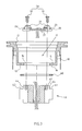
- FIG. 3 shows an exploded sectional view of the preferred embodiment of the present invention.
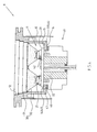
- FIG. 4 shows an assembled sectional view of the preferred embodiment of the present invention.
- FIGS. 1-4 depict preferred embodiments of a combined cooling seat of an LED lamp of the present invention. The embodiments are provided only for explanatory purposes with respect to the patent claims.
- the LED lamp A comprises a main body 10, a LED baseplate 20, a light projector 30, and a cooling seat 40.
- the main body 10 is provided with an inner space 11, which forms an open end 12 and an inner wall 13.
- the LED baseplate 20 is mounted into the inner space 11, and some LEDs 21 are placed in front of the LED baseplate 20.
- the light projector 30 is assembled in the open end 12 of the inner space 11.
- the inner wall 13 is provided with a reducing through-hole 14, while a front stop edge 15 and a rear stop edge 16 are formed on the wall of the reducing through-hole 14.
- the back side 22 of LED baseplate 20 is sustained by the front stop edge 15.
- One end of the cooling seat 40 is provided with an insertion portion 41 for plugging into the reducing through-hole 14 on the inner wall 13 of the inner space 11.
- One end surface 42 of the cooling seat 40 is sustained by the back side 22 of LED baseplate 20.
- a retaining edge 43 is arranged around the other end of the cooling seat 40 for positioning at the rear stop edge 16.
- the LED baseplate 20 and cooling seat 40 are positioned through a locator 50.
- the locator 50 is made of a plurality of bolts 51, such that LED baseplate 20 and cooling seat 40 are separately provided with punch hole 23 and screw hole 44.
- the bolts 51 could be screwed into the screw hole 44 after passing the punch hole 23, thus enabling the positioning of LED baseplate 20 and cooling seat 40.
- the light projector 30 comprises a light shield 31 and several refraction blocks 32.
- the light shield 31 is provided with several through-holes 33 for sleeving of the refraction block 32.
- a soft pad 60 is arranged between the retaining edge 43 of cooling seat 40 and the rear stop edge 16 of the main body 10.
- the soft pad 60 is made of rubber or silica gel, which allows the cooling seat 40 and LED baseplate 20 to be coupled more firmly and securely.
- the LED lamp A of the present invention allows the cooling seat 40 to be integrated and assembled in a more simple way.
- the cooling seat 40, the main body 10 and LED baseplate 20 are to be assembled together, the LED baseplate 20 is inserted into the inner space 11.
- the back side 22 is sustained by the front stop edge 15 of the reducing through-hole 14.
- one end of the main body 10 with inner wall 13 is adapted to the main body 10. Then, the insertion portion 41 of the cooling seat 40 is inserted into the reducing through-hole 14 of the inner wall 13.
- the end surface 42 of the cooling seat 40 is sustained by the back side 22 of the LED baseplate 20, and the retaining edge 43 of the cooling seat 40 is sustained by the rear stop edge 16 formed on the wall of the reducing through-hole 14.
- the bolts 51 of the locator 50 could be screwed into the screw hole 44 after passing the punch hole 23 of LED baseplate 20, thus enabling the positioning of LED baseplate 20, cooling seat 40 and main body 10.
- the LED lamp A of the present invention is assembled through a single locator 50, in combination with the front and rear stop edges 15, 16 on the inner wall 13 of the main body 10 which are used for limitation of the LED baseplate 20 and cooling seat 40.
- the cooling seat 40 and main body 10 can be positioned quickly.
- the end surface 42 of the cooling seat 40 could be directly sustained by the back side 22 of the LED baseplate 20, thus permitting fast heat radiation with better heat transfer and elimination effect.
Landscapes
- Engineering & Computer Science (AREA)
- General Engineering & Computer Science (AREA)
- Non-Portable Lighting Devices Or Systems Thereof (AREA)
- Arrangement Of Elements, Cooling, Sealing, Or The Like Of Lighting Devices (AREA)
Applications Claiming Priority (1)
| Application Number | Priority Date | Filing Date | Title |
|---|---|---|---|
| TW096221435U TWM332794U (en) | 2007-12-17 | 2007-12-17 | Structure improvement on heat radiating seat assembly of LED |
Publications (1)
| Publication Number | Publication Date |
|---|---|
| EP2072893A1 true EP2072893A1 (fr) | 2009-06-24 |
Family
ID=39684281
Family Applications (1)
| Application Number | Title | Priority Date | Filing Date |
|---|---|---|---|
| EP08008954A Withdrawn EP2072893A1 (fr) | 2007-12-17 | 2008-05-14 | Lampe à diode électroluminescente (LED) dotée d'un siège de refroidissement |
Country Status (2)
| Country | Link |
|---|---|
| EP (1) | EP2072893A1 (fr) |
| TW (1) | TWM332794U (fr) |
Cited By (2)
| Publication number | Priority date | Publication date | Assignee | Title |
|---|---|---|---|---|
| WO2011114226A2 (fr) | 2010-03-17 | 2011-09-22 | Antonio Di Gangi | Corps à ailettes pour appareil d'éclairage led et appareil d'éclairage en comportant |
| ITUD20120092A1 (it) * | 2012-05-18 | 2013-11-19 | Martini Spa | Dispositivo di illuminazione a led |
Citations (5)
| Publication number | Priority date | Publication date | Assignee | Title |
|---|---|---|---|---|
| DE20315760U1 (de) * | 2003-10-09 | 2004-02-26 | Bocom Energiespar-Technologien Gmbh | Leuchte mit Leuchtdioden |
| EP1577613A2 (fr) * | 2004-03-10 | 2005-09-21 | Conrad Electronic GmbH | Lampe pour dispositif d'éclairage |
| EP1705421A2 (fr) | 2005-03-23 | 2006-09-27 | Nuriplan Co., Ltd. | Lampe à diodes électroluminescentes |
| DE102006017718A1 (de) * | 2005-10-27 | 2007-05-16 | Kromberg & Schubert Gmbh & Co | Leuchte |
| DE202007003679U1 (de) * | 2007-03-09 | 2007-05-16 | Hong Kuan Technology Co., Ltd., Sinjhuang City | Leuchtdiodenlampe |
-
2007
- 2007-12-17 TW TW096221435U patent/TWM332794U/zh not_active IP Right Cessation
-
2008
- 2008-05-14 EP EP08008954A patent/EP2072893A1/fr not_active Withdrawn
Patent Citations (5)
| Publication number | Priority date | Publication date | Assignee | Title |
|---|---|---|---|---|
| DE20315760U1 (de) * | 2003-10-09 | 2004-02-26 | Bocom Energiespar-Technologien Gmbh | Leuchte mit Leuchtdioden |
| EP1577613A2 (fr) * | 2004-03-10 | 2005-09-21 | Conrad Electronic GmbH | Lampe pour dispositif d'éclairage |
| EP1705421A2 (fr) | 2005-03-23 | 2006-09-27 | Nuriplan Co., Ltd. | Lampe à diodes électroluminescentes |
| DE102006017718A1 (de) * | 2005-10-27 | 2007-05-16 | Kromberg & Schubert Gmbh & Co | Leuchte |
| DE202007003679U1 (de) * | 2007-03-09 | 2007-05-16 | Hong Kuan Technology Co., Ltd., Sinjhuang City | Leuchtdiodenlampe |
Cited By (2)
| Publication number | Priority date | Publication date | Assignee | Title |
|---|---|---|---|---|
| WO2011114226A2 (fr) | 2010-03-17 | 2011-09-22 | Antonio Di Gangi | Corps à ailettes pour appareil d'éclairage led et appareil d'éclairage en comportant |
| ITUD20120092A1 (it) * | 2012-05-18 | 2013-11-19 | Martini Spa | Dispositivo di illuminazione a led |
Also Published As
| Publication number | Publication date |
|---|---|
| TWM332794U (en) | 2008-05-21 |
Similar Documents
| Publication | Publication Date | Title |
|---|---|---|
| US20090201683A1 (en) | Light-emitting diode (led) lamp with a cooling seat | |
| CN203036563U (zh) | 灯壳结构 | |
| JP2010198828A (ja) | 照明装置 | |
| KR101226215B1 (ko) | Led 방열장치 | |
| TW200606371A (en) | Integral reflector and heat sink | |
| TW200702615A (en) | Heat sink structure | |
| CN202274356U (zh) | 一种带风扇的led工矿灯 | |
| CN205101912U (zh) | Led灯泡 | |
| CN203322799U (zh) | 一种led筒灯 | |
| ATE472924T1 (de) | Licht und wärmestrahler | |
| CN103322452B (zh) | 一种led筒灯 | |
| CN201072050Y (zh) | 路灯散热装置 | |
| CN104763981A (zh) | Led灯具的热沉外壳及使用该热沉外壳的led灯具 | |
| CN206846661U (zh) | 一种斗胆灯 | |
| EP2072892A1 (fr) | Abat-jour de lampe à diode électroluminescente (LED) | |
| CN202216219U (zh) | 具防护与较佳散热的散热器及其散热片 | |
| GB0412614D0 (en) | Heat dissipating device with fins inclinedly connected to base | |
| CN204254328U (zh) | 一种卡扣式球泡灯 | |
| CN2932083Y (zh) | 灯具散热结构 | |
| TWM325447U (en) | LED heat sink module | |
| TWM332794U (en) | Structure improvement on heat radiating seat assembly of LED | |
| CN201170528Y (zh) | 散热结构 | |
| CN201246699Y (zh) | 灯具及其固定座 | |
| CN101900254B (zh) | 散热led灯 | |
| CN206846366U (zh) | 一种球泡灯 |
Legal Events
| Date | Code | Title | Description |
|---|---|---|---|
| PUAI | Public reference made under article 153(3) epc to a published international application that has entered the european phase |
Free format text: ORIGINAL CODE: 0009012 |
|
| AK | Designated contracting states |
Kind code of ref document: A1 Designated state(s): AT BE BG CH CY CZ DE DK EE ES FI FR GB GR HR HU IE IS IT LI LT LU LV MC MT NL NO PL PT RO SE SI SK TR |
|
| AX | Request for extension of the european patent |
Extension state: AL BA MK RS |
|
| 17P | Request for examination filed |
Effective date: 20090528 |
|
| RIN1 | Information on inventor provided before grant (corrected) |
Inventor name: TANG, SHIH-CHUAN |
|
| AKX | Designation fees paid |
Designated state(s): AT BE BG CH CY CZ DE DK EE ES FI FR GB GR HR HU IE IS IT LI LT LU LV MC MT NL NO PL PT RO SE SI SK TR |
|
| 17Q | First examination report despatched |
Effective date: 20101110 |
|
| STAA | Information on the status of an ep patent application or granted ep patent |
Free format text: STATUS: THE APPLICATION IS DEEMED TO BE WITHDRAWN |
|
| 18D | Application deemed to be withdrawn |
Effective date: 20110322 |