EP2072929A1 - Climatiseur - Google Patents
Climatiseur Download PDFInfo
- Publication number
- EP2072929A1 EP2072929A1 EP07828275A EP07828275A EP2072929A1 EP 2072929 A1 EP2072929 A1 EP 2072929A1 EP 07828275 A EP07828275 A EP 07828275A EP 07828275 A EP07828275 A EP 07828275A EP 2072929 A1 EP2072929 A1 EP 2072929A1
- Authority
- EP
- European Patent Office
- Prior art keywords
- filter
- guide
- moving direction
- portions
- air conditioner
- Prior art date
- Legal status (The legal status is an assumption and is not a legal conclusion. Google has not performed a legal analysis and makes no representation as to the accuracy of the status listed.)
- Withdrawn
Links
Images




Classifications
-
- F—MECHANICAL ENGINEERING; LIGHTING; HEATING; WEAPONS; BLASTING
- F24—HEATING; RANGES; VENTILATING
- F24F—AIR-CONDITIONING; AIR-HUMIDIFICATION; VENTILATION; USE OF AIR CURRENTS FOR SCREENING
- F24F13/00—Details common to, or for air-conditioning, air-humidification, ventilation or use of air currents for screening
- F24F13/28—Arrangement or mounting of filters
-
- B—PERFORMING OPERATIONS; TRANSPORTING
- B01—PHYSICAL OR CHEMICAL PROCESSES OR APPARATUS IN GENERAL
- B01D—SEPARATION
- B01D46/00—Filters or filtering processes specially modified for separating dispersed particles from gases or vapours
- B01D46/0052—Filters or filtering processes specially modified for separating dispersed particles from gases or vapours with filtering elements moving during filtering operation
- B01D46/0054—Filters or filtering processes specially modified for separating dispersed particles from gases or vapours with filtering elements moving during filtering operation with translational movement
-
- B—PERFORMING OPERATIONS; TRANSPORTING
- B01—PHYSICAL OR CHEMICAL PROCESSES OR APPARATUS IN GENERAL
- B01D—SEPARATION
- B01D46/00—Filters or filtering processes specially modified for separating dispersed particles from gases or vapours
- B01D46/10—Particle separators, e.g. dust precipitators, using filter plates, sheets or pads having plane surfaces
-
- F—MECHANICAL ENGINEERING; LIGHTING; HEATING; WEAPONS; BLASTING
- F24—HEATING; RANGES; VENTILATING
- F24F—AIR-CONDITIONING; AIR-HUMIDIFICATION; VENTILATION; USE OF AIR CURRENTS FOR SCREENING
- F24F1/00—Room units for air-conditioning, e.g. separate or self-contained units or units receiving primary air from a central station
- F24F1/0007—Indoor units, e.g. fan coil units
- F24F1/0043—Indoor units, e.g. fan coil units characterised by mounting arrangements
- F24F1/0057—Indoor units, e.g. fan coil units characterised by mounting arrangements mounted in or on a wall
-
- F—MECHANICAL ENGINEERING; LIGHTING; HEATING; WEAPONS; BLASTING
- F24—HEATING; RANGES; VENTILATING
- F24F—AIR-CONDITIONING; AIR-HUMIDIFICATION; VENTILATION; USE OF AIR CURRENTS FOR SCREENING
- F24F8/00—Treatment, e.g. purification, of air supplied to human living or working spaces otherwise than by heating, cooling, humidifying or drying
- F24F8/90—Cleaning of purification apparatus
-
- B—PERFORMING OPERATIONS; TRANSPORTING
- B01—PHYSICAL OR CHEMICAL PROCESSES OR APPARATUS IN GENERAL
- B01D—SEPARATION
- B01D2279/00—Filters adapted for separating dispersed particles from gases or vapours specially modified for specific uses
- B01D2279/50—Filters adapted for separating dispersed particles from gases or vapours specially modified for specific uses for air conditioning
Definitions
- the present invention relates to an air conditioner. More specifically, the present invention relates to an air conditioner equipped with a filter cleaning mechanism that cleans a filter by moving the filter.
- a filter cleaning mechanism of an air conditioner having a configuration as described above includes a sheet-like filter disposed so as to be able to freely reciprocate along the inner surface of an air suction port; a dust box disposed in a reciprocating path of the filter; and a brush disposed so as to sandwich the filter from both front and back surfaces thereof in the dust box. Additionally, dust adhering to the surface of the filter that reciprocates in the dust box is wiped off with a brush so as to reproduce the function of the filter.
- the filter cleaning mechanism is configured such that the filter is latched in annular belts wound between pairs of pulleys and the filter is reciprocated along with the reciprocative rotation of the annular belt, when the filter is bent and rotated 180 degrees or so, the filter may sag and get caught by a filter guide. When that happens, the filter cannot be smoothly moved.
- the present invention is made in light of the above problem, and aims to allow smooth movement of a filter by preventing the filter from getting caught during rotation of the filter.
- An air conditioner includes an air conditioning mechanism, a cleaning mechanism, and a filter guide.
- the air conditioning mechanism includes a heat exchanger and a fan disposed in a ventilation passage.
- the ventilation passage is an air passage extending from a suction port, which is formed across the area from the front side of the casing to the upper side thereof, to a discharge port formed at the bottom side of the casing.
- the cleaning mechanism removes dust adhering to the surface of a sheet-like filter arranged capable of moving along the suction port by moving the filter from a position where a specific filter function is demonstrated, and after the removal of dust, the cleaning mechanism returns the filter to the position where the specific filter function is demonstrated.
- the filter guide guides the movement of the filter.
- the filter includes a filter member and support portions that support the filter member. Additionally, one or a plurality of filter function units, each of which being the filter member surrounded by the support portions, are formed to the filter.
- the filter guide is provided with a catch prevention member that guides both side portions of the filter function unit in the filter moving direction.
- the filter guide is configured such that the filter guide is provided with a guide portion that allows the both side portions of the filter function unit in the filter moving direction to be guided before the center portion of the filter function unit in the filter moving direction and such that the catch prevention member is a part of the guide portion, the filter guide can be made small and the center portion of the filter function unit in the filter moving direction can be further reliably corrected.
- the catch prevention member preferably has a curved surface and the guide portion preferably has a U-shaped surface including the curved surface of the catch prevention member.
- the filter guide is configured such that the filter guide includes a plurality of guide portions arranged along the filter moving direction and such that the catch prevention member comprises bars that extend in a direction crossing the filter moving direction so as to connect the plurality of guide portions, sagging of the center portion of the filter function unit in the filter moving direction can be further reliably corrected. Also in this case, an ingenious modification of the structure of the bars provided to the filter guide can produce effects such as a reduction of the size of the filter guide and smooth movement of the filter.
- sagging of the center portion of a filter function unit in a filter moving direction during rotation of a filter is corrected, which consequently allows smooth movement of the filter.
- An air conditioner according to an embodiment of the present invention is a separate type air conditioner.
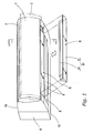
- An indoor unit of the air conditioner is shown in Figures 1 and 2 .
- This indoor unit includes a horizontally elongated box-shaped casing 1 attached to the indoor wall surface.
- the casing 1 includes a front side suction port 3A formed in a front wall 1A, and an upper side suction port 3B formed in a top wall 1B.
- a front panel 2 is provided in front of the front side suction port 3A.
- the front panel 2 moves downward from a closed position where the front panel 2 is near the front side suction port 3A and covers the front side suction port 3A as shown by the solid lines in Figures 1 and 2 , to an open position where the front panel 2 is forwardly inclined with its upper end sticking out forward as shown by the two-dot chain lines in Figures 1 and 2 .
- the front panel 2 is configured to be able to open and close the front side suction port 3A between the open position and the closed position, and to open the front side suction port 3A at the open position.
- a discharge port 4 having a horizontally elongated opening shape is disposed at the middle portion in the front and back direction of a bottom wall 1C of the casing 1.
- the discharge port 4 is disposed with a horizontal flap 44 and a vertical flap 45.
- a brush mechanism Q (described below) having a dust box 20 is removably mounted in a housing 30.
- the housing 30 is disposed at a position in front of the discharge port 4 and near the lower end of the front wall 1A.
- a heat exchanger 7 and a fan 8 are disposed in a ventilation passage 5 formed from a suction port 3 (i.e., the front side suction port 3A and the upper side suction port 3B) to the discharge port 4.
- An air conditioning mechanism X is formed by the heat exchanger 7 and the fan 8.
- the heat exchanger 7 is formed by a first heat exchanger 7A facing the suction port 3 (mainly, the front side suction port 3A) with a space therefrom and extending in the up-down direction, and a second heat exchanger 7B connected to the upper end of the first heat exchanger 7A and inclined downward to a back wall 1D side.
- the heat exchanger 7 is in a bent form having a substantially mountain shape.
- the casing 1 there are a front space formed between the front side suction port 3A and the front side of the first heat exchanger 7A, and an upper space formed between the upper side suction port 3B and the top portions of the first heat exchanger 7A and the second heat exchanger 7B.
- a filter 13, a cleaning unit casing 14, a cleaning mechanism Y, and the like are disposed across these spaces.
- the filter 13 is a flexible sheet-like filter, and includes a rectangular frame body 25, grille bars 26, and a filter member 27. As described below, the filter 13 is guided by the cleaning unit casing 14 that includes guide grooves 15a and 16a and a filter pusher 43 (described below) such that the filter 13 can reciprocate between a "first filter position" near the suction port 3 and a "second filter position” nearer the heat exchanger 7 than the suction port 3.
- the frame body 25 of the filter 13 is formed by side frames 25A positioned at both sides of the frame body 25 in the filter moving direction (i.e., both left and right sides in the front view) and front and back frames 25B positioned at the front and back of the frame body 25 in the filter moving direction.
- the grille bars 26 connect each of the frames 25A and 25B and are integrally formed with the frame body 25.
- the filter member 27 is disposed in a quadrangular shaped section surrounded by the frame body 25 and the grille bars 26.
- the frame body 25 and the grille bars 26 act as the support portions for supporting the filter member 27.
- the filter 13 shown in Figure 4 has nine sections each formed by the filter member 27 whose surrounding four sides are supported by the frame body 25 and the grille bars 26.
- Each of these nine sections formed by the filter members 27 is a filter function unit that demonstrates a filter function of collecting dust in the air when the air passes therethrough.
- the indoor unit of this air conditioner is configured such that the filter 13 is mounted to each of the left and right sides, and each filter 13 has nine filter function units.
- portions in each filter function unit which are near the frame body 25 or the grille bars 26 in the left-right direction are referred to as "both side portions 27A in the filter moving direction” and a portion in each filter function unit which is away from the frame body 25 or the grille bars 26 in the left-right direction is referred to as a "center portion 27B in the filter moving direction" (see Figure 4 ).
- a number of projections 28 arranged at an equal pitch in the filter moving direction are integrally formed with the side frames 25A of the filter 13 so as to project therefrom.
- the cross-section of the cleaning unit casing 14 has a curved shape that follows the longitudinal cross sectional shape from the front side suction port 3A to the upper side suction port 3B of the casing 1.
- the cleaning unit casing 14 has a horizontally elongated shape and is fixed to the casing 1.
- the cleaning unit casing 14 is made of resin, and includes a left and right pair of side wall portions 15, a middle wall portion 16 located between theses side wall portions 15, and a grating shaped bars 17 disposed between the side wall portions 15 and the middle wall portion 16.
- the side wall portions 15, the middle wall portion 16, and the bars 17 are integrally formed together, and they also play the role of guiding the filter 13.
- the side wall portions 15 and the middle wall portion 16 of the cleaning unit casing 14 are provided with the guide grooves 15a and 16a, respectively.
- the filter 13 is arranged between the guide groove 15a of one of the side wall portions 15 and the guide groove 16a of the middle wall portion 16, and also between the guide groove 15a of the other one of the side wall portions 15 and the guide groove 16a of the middle wall portion 16, such that each filter 13 can move along the cross-sectionally curved shape of the cleaning unit casing 14.
- the cleaning unit casing 14 includes the filter pusher 43 that externally covers the front portion (i.e., front side) of the filter 13 disposed at a position facing the front side suction port 3A of the casing 1.
- the filter pusher 43 plays the role of holding down the filter 13 in place (preventing the film 13 from bulging out forward) during movement of the filter 13.
- the filter pusher 43 is made of resin, and can rotate about its upper edge portion.
- the filter pusher 43 is provided to each of the left and right sides, and each filter pusher 43 includes left-right guide portions 43A, front-back guide portions 43B, and the bars 17.
- the left-right guide portions 43A and the bars 17 extend in the up-down direction
- the front-back guide portions 43B extend in the left-right direction.
- the left-right guide portions 43A and the bars 17 connect between the upper front-back guide portion 43B and the lower front-back guide portion 43B, and are integrally formed with the front-back guide portions 43B.
- the left-right guide portions 43A of the filter pusher 43 align with the side wall portions 15 and the middle wall portion 16 described above in the left-right direction.
- the positions of the bars 17 of the filter pusher 43 in the left-right direction align with the positions of the forwardly and rearwardly extending portions of the bars 17 in the left-right direction which are integrally formed with the side wall portions 15 and the middle wall portion 16.
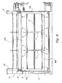
- catch prevention members R are formed to each front-back guide portion 43B of the filter pusher 43.
- the left-right guide portions 43A of the filter pusher 43 are located at the same positions as the side frames 25A of the filter 13, and the bars 17 of the filter pusher 43 are located at the same positions as the upwardly and downwardly extending portions of the grille bars 26 of the filter 13.
- the catch prevention members R of the front-back guide portions 43B are located at the same position as the both side portions 27A of each filter function unit in the filter moving direction of the filter 13.
- each catch prevention member R has a curved surface.
- the front-back guide portions 43B have U-shaped surfaces including the curved surfaces.
- Figure 8 clearly shows the catch prevention members R formed in the front-back guide portions 43B of the filter pusher 43; however, the illustration of the catch prevention members R is omitted in Figure 3 .
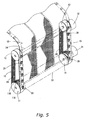
- a number of projections 28 on the side frames 25A of the filter 13 are latched in annular belts 10 at the front portion (a portion facing the front side suction port 3A) of the cleaning unit casing 14.
- the annular belts 10 are wound between first pulleys 11 and second pulleys 12 arranged in a parallel manner with a space therebetween in the up-down direction.
- the filter 13 is latched in the annular belts 10 as the projections 28 of the filter 13 are engaged with a number of engaging holes 29 formed side-by-side at an equal pitch on each annular belt 10. Thereby, the filter 13 moves as the annular belts 10 run.
- each engaging hole 29 of the annular belts 10 be formed in an oval shape having a long axis in the filter moving direction. It is because such a shape provides greater flexibility when engaging the projections 28 with the engaging holes 29.
- the space between each engaging hole 29 be equal to the space between each projection 28, however, the space between each projection 28 may be equal to the integral multiple of the space between each engaging hole 29.
- the annular belts 10 and the first and second pulleys 11 and 12 are configured to move in synchronization as bumps formed on the inner surface of the annular belts 10 mate with bumps 11 a and 12a formed on the outer circumference of the first and second pulleys 11 and 12.
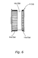
- the outer circumference of each of the first and second pulleys 11 and 12 is disposed with projection avoiding portions 11b and 12b formed by cutting out the bumps 11a and 12a in order to avoid interference with the projections 28 of the filter 13 (see Figure 6 ).
- reference symbols 31 and 32 represent motors as driving means for rotatingly driving the first pulleys 11 and the second pulleys 12, respectively.
- reference symbol 33 represents the drive axis for synchronously driving the first pulleys 11, 11 on the left and right sides
- reference symbol 34 represents the drive axis for synchronously driving the second pulleys 12, 12 on the left and right sides.
- the brush mechanism Q is removably attached to the housing 30 provided at the front end portion of the bottom wall 1C of the casing 1.
- the brush mechanism Q is formed by arranging a cleaning brush 23 in the dust box 20 comprising a first box body 21 and a second box body 22.
- the cleaning brush 23 is rotatingly driven by a brush drive motor (not shown).
- the basic arrangement of the filter 13 is such that its upper end is located at the upper end portion of the cleaning unit casing 14, and its lower end is located in the vicinity of the first pulley 11.
- This arrangement represents the position of the filter 13 during a normal air conditioning operation, and this position is referred to as a "first filter position" below.
- the first and second pulleys 11 and 12 rotate in the normal direction, and the annular belts 10 run in the direction of arrow b (see Figure 2 ).
- the filter 13 moves from the "first filter position" along with the annular belts 10 as shown by the two-dot chain lines in Figure 7 , rotates externally around the first pulleys 11, moves to the back sides of the second pulleys 12, and further moves upward of the second pulleys 12.
- the position of the filter 13 after being moved as a result of rotation of the first and second pulleys 11 and 12 in the normal direction is referred to as a "second filter position" below.
- the filter 13 reciprocates between the "first filter position” and the "second filter position". It was assumed at the time of designing of the indoor unit that the filter 13 could not move smoothly because the filter 13 would sag during reciprocation (in particular, during rotation in which the filter 13 moves around the first pulleys 11) and a portion of the filter 13 would get caught by the front-back guide portions 43B of the filter pusher 43 which act as the filter guides.
- the catch prevention members R are formed in the front-back guide portions 43B of the filter pusher 43. This produces an effect that prevents the center portion 27B of each filter function unit in the filter moving direction of the filter 13 from bulging too much, which otherwise tends to sag outwardly and bulge when moving and rotating about 180 degrees or so around the first pulleys 11.
- the front-back guide portions 43B is configured such that the catch prevention members R first come into contact with the both side portions 27A of each filter function unit in the filter moving direction, and push down the bulges of the both side portions 27A in the filter moving direction, thereby reducing the size of the bulge of the center portion 27B in the filter moving direction, and by the time when the center portion 27B in the filter moving direction subsequently comes into contact with the front-back guide portions 43B, the center portion 27B in the filter moving direction will be in a form in which the center portion 27B in the filter moving direction does not get caught by the front-back guide portions 43B (the bulge is small).
- the front-back guide portions 43B including the catch prevention members R correct sagging of the center portion 27B in the filter moving direction by guiding the both side portions 27A in the filter moving direction of the filter 13 before the center portion 27B in the filter moving direction, thus allowing smooth movement of the filter 13.
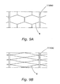
- the catch prevention members R are formed in the front-back guide portions 43B of the filter pusher 43, however, when the filter 13 as shown in Figure 10A is employed, a filter pusher having bars R formed as shown in Figure 9A as the catch prevention members is used.
- the grille bars 26 of the filter 13 are modified and there are four filter function units.
- the bars R that extend between the upwardly and downwardly extending bars 17 or the left-right guide portions 43A form hexagonal shapes. In this case, the bars R that are inclined when viewed from the front perform the function as the catch prevention members.
- the catch prevention members R are formed in the front-back guide portions 43B of the filter pusher 43, however, when the filter 13 as shown in Figure 10B is employed, a filter pusher having the bars R formed as shown in Figure 9B as the catch prevention members is used.
- the filter 13 does not include the grille bars 26 and the filter 13 includes only one filter function unit. Additionally, in the filter pusher shown in Figure 9B , the bars R that extend between the upwardly and downwardly extending bars 17 or the left-right guide portions 43A are arranged obliquely. In this case, the bars R perform the function as the catch prevention members.
- the driving means comprising the pulleys 11 and 12 and the annular belt 10 is employed to reciprocate the filter 13, however, the present invention is not limited thereto, and rack and pinion driving means can be employed.
Landscapes
- Engineering & Computer Science (AREA)
- Chemical & Material Sciences (AREA)
- Combustion & Propulsion (AREA)
- Mechanical Engineering (AREA)
- General Engineering & Computer Science (AREA)
- Chemical Kinetics & Catalysis (AREA)
- Air Filters, Heat-Exchange Apparatuses, And Housings Of Air-Conditioning Units (AREA)
Applications Claiming Priority (2)
| Application Number | Priority Date | Filing Date | Title |
|---|---|---|---|
| JP2006259237 | 2006-09-25 | ||
| PCT/JP2007/068280 WO2008038570A1 (fr) | 2006-09-25 | 2007-09-20 | Climatiseur |
Publications (2)
| Publication Number | Publication Date |
|---|---|
| EP2072929A1 true EP2072929A1 (fr) | 2009-06-24 |
| EP2072929A4 EP2072929A4 (fr) | 2012-02-15 |
Family
ID=39230004
Family Applications (1)
| Application Number | Title | Priority Date | Filing Date |
|---|---|---|---|
| EP07828275A Withdrawn EP2072929A4 (fr) | 2006-09-25 | 2007-09-20 | Climatiseur |
Country Status (4)
| Country | Link |
|---|---|
| EP (1) | EP2072929A4 (fr) |
| JP (1) | JP5163495B2 (fr) |
| CN (1) | CN101517333B (fr) |
| WO (1) | WO2008038570A1 (fr) |
Cited By (1)
| Publication number | Priority date | Publication date | Assignee | Title |
|---|---|---|---|---|
| EP2613101A4 (fr) * | 2010-09-03 | 2018-04-04 | Daikin Industries, Ltd. | Mécanisme de déplacement de filtre, et appareil intérieur de conditionnement d'air |
Families Citing this family (5)
| Publication number | Priority date | Publication date | Assignee | Title |
|---|---|---|---|---|
| JP5787497B2 (ja) * | 2010-08-05 | 2015-09-30 | 三菱重工業株式会社 | 空気調和機 |
| JP6299718B2 (ja) * | 2015-09-30 | 2018-03-28 | ダイキン工業株式会社 | 空気調和装置 |
| CN109364638B (zh) * | 2018-12-07 | 2020-11-17 | 佛山同兴制药有限公司 | 一种药材粉尘过滤除尘装置 |
| US11298638B2 (en) * | 2020-01-08 | 2022-04-12 | Haier Us Appliance Solutions, Inc. | Automatic clean air filter for air conditioner unit |
| CN113274815B (zh) * | 2021-07-12 | 2021-11-16 | 深圳世通机电有限公司 | 一种滑移式的空气处理设备 |
Family Cites Families (8)
| Publication number | Priority date | Publication date | Assignee | Title |
|---|---|---|---|---|
| US3717978A (en) * | 1971-07-09 | 1973-02-27 | E Osborne | Air filter system |
| JPS56168047A (en) * | 1980-05-29 | 1981-12-24 | Mitsubishi Electric Corp | Filter apparatus for air conditioner |
| JPS6369523U (fr) * | 1986-10-24 | 1988-05-10 | ||
| JP4110375B2 (ja) * | 2002-06-27 | 2008-07-02 | 株式会社富士通ゼネラル | 空気調和機 |
| JP4041962B2 (ja) | 2002-09-11 | 2008-02-06 | 株式会社富士通ゼネラル | 空気調和機 |
| JP4154574B2 (ja) * | 2002-09-25 | 2008-09-24 | 株式会社富士通ゼネラル | 空気調和機 |
| KR101065965B1 (ko) * | 2003-08-18 | 2011-09-19 | 파나소닉 주식회사 | 에어 필터의 자동 청소 기능이 부가된 실내 유닛을 구비한 공기 조화기 |
| US7544223B2 (en) * | 2004-09-02 | 2009-06-09 | Fujitsu General Limited | Air conditioner |
-
2007
- 2007-09-20 WO PCT/JP2007/068280 patent/WO2008038570A1/fr not_active Ceased
- 2007-09-20 JP JP2008536347A patent/JP5163495B2/ja not_active Expired - Fee Related
- 2007-09-20 CN CN2007800348639A patent/CN101517333B/zh not_active Expired - Fee Related
- 2007-09-20 EP EP07828275A patent/EP2072929A4/fr not_active Withdrawn
Cited By (1)
| Publication number | Priority date | Publication date | Assignee | Title |
|---|---|---|---|---|
| EP2613101A4 (fr) * | 2010-09-03 | 2018-04-04 | Daikin Industries, Ltd. | Mécanisme de déplacement de filtre, et appareil intérieur de conditionnement d'air |
Also Published As
| Publication number | Publication date |
|---|---|
| CN101517333A (zh) | 2009-08-26 |
| JPWO2008038570A1 (ja) | 2010-01-28 |
| JP5163495B2 (ja) | 2013-03-13 |
| EP2072929A4 (fr) | 2012-02-15 |
| WO2008038570A1 (fr) | 2008-04-03 |
| CN101517333B (zh) | 2011-07-20 |
Similar Documents
| Publication | Publication Date | Title |
|---|---|---|
| JP4384115B2 (ja) | エアフィルタの自動清掃機能付き室内ユニットを備えた空気調和機 | |
| JP6423626B2 (ja) | 空気調和機 | |
| JP5163495B2 (ja) | 空気調和機 | |
| KR101049775B1 (ko) | 공기 조화기 | |
| JP5240020B2 (ja) | 空気調和機 | |
| CN101517332B (zh) | 过滤器及使用该过滤器的空调机 | |
| JP4915351B2 (ja) | 空気調和機 | |
| JP2009257735A (ja) | 空気調和機 | |
| JP2010151333A (ja) | 空気調和機の室内機 | |
| JP4533366B2 (ja) | フィルタ及びフィルタ清掃装置及び空気調和機 | |
| JP2006112699A (ja) | 空気調和機のフィルタ装置 | |
| JP2012087969A (ja) | 空気調和機 | |
| JP2007152307A (ja) | フィルター及びフィルター送り装置 | |
| JP5595839B2 (ja) | 空気調和機の室内機 | |
| JP7033028B2 (ja) | 空気調和装置 | |
| JP2012102984A (ja) | 空気調和機 | |
| JP4915352B2 (ja) | 空気調和機 | |
| KR20060054075A (ko) | 공기 조화기 | |
| JP5040670B2 (ja) | 空気調和機 | |
| JP4600378B2 (ja) | 空気調和機 | |
| JP2012083104A (ja) | 空気調和機 | |
| JP2009115383A (ja) | フィルタ清掃装置 | |
| JP2008095975A (ja) | 空気調和機 | |
| JP2026050131A (ja) | フィルタクリーニング機構及び空気調和装置 | |
| JP2008111579A (ja) | フィルタ清掃装置および空気調和機 |
Legal Events
| Date | Code | Title | Description |
|---|---|---|---|
| PUAI | Public reference made under article 153(3) epc to a published international application that has entered the european phase |
Free format text: ORIGINAL CODE: 0009012 |
|
| 17P | Request for examination filed |
Effective date: 20090415 |
|
| AK | Designated contracting states |
Kind code of ref document: A1 Designated state(s): AT BE BG CH CY CZ DE DK EE ES FI FR GB GR HU IE IS IT LI LT LU LV MC MT NL PL PT RO SE SI SK TR |
|
| AX | Request for extension of the european patent |
Extension state: AL BA HR MK RS |
|
| A4 | Supplementary search report drawn up and despatched |
Effective date: 20120113 |
|
| RIC1 | Information provided on ipc code assigned before grant |
Ipc: B01D 46/00 20060101ALI20120109BHEP Ipc: B01D 46/10 20060101ALI20120109BHEP Ipc: F24F 13/28 20060101AFI20120109BHEP |
|
| DAX | Request for extension of the european patent (deleted) | ||
| 17Q | First examination report despatched |
Effective date: 20130124 |
|
| STAA | Information on the status of an ep patent application or granted ep patent |
Free format text: STATUS: THE APPLICATION HAS BEEN WITHDRAWN |
|
| 18W | Application withdrawn |
Effective date: 20140908 |