EP2072945A1 - Plaque de blindage composite - Google Patents
Plaque de blindage composite Download PDFInfo
- Publication number
- EP2072945A1 EP2072945A1 EP09002896A EP09002896A EP2072945A1 EP 2072945 A1 EP2072945 A1 EP 2072945A1 EP 09002896 A EP09002896 A EP 09002896A EP 09002896 A EP09002896 A EP 09002896A EP 2072945 A1 EP2072945 A1 EP 2072945A1
- Authority
- EP
- European Patent Office
- Prior art keywords
- rod
- shaped elements
- composite armor
- armor plate
- plate according
- Prior art date
- Legal status (The legal status is an assumption and is not a legal conclusion. Google has not performed a legal analysis and makes no representation as to the accuracy of the status listed.)
- Granted
Links
Images



Classifications
-
- F—MECHANICAL ENGINEERING; LIGHTING; HEATING; WEAPONS; BLASTING
- F41—WEAPONS
- F41H—ARMOUR; ARMOURED TURRETS; ARMOURED OR ARMED VEHICLES; MEANS OF ATTACK OR DEFENCE, e.g. CAMOUFLAGE, IN GENERAL
- F41H5/00—Armour; Armour plates
- F41H5/02—Plate construction
- F41H5/04—Plate construction composed of more than one layer
- F41H5/0492—Layered armour containing hard elements, e.g. plates, spheres, rods, separated from each other, the elements being connected to a further flexible layer or being embedded in a plastics or an elastomer matrix
Definitions
- the invention relates to a composite armor plate for protection against projectiles with the features of the preamble of patent claim 1.
- Composite armor plates which consist of a composite of several materials, are known per se. Frequently composite armor plates are constructed such that between two plate elements filling materials or filling elements are introduced, which are then encapsulated with a pourable mass.
- the DE 1 578 324 describes such a plate, being used as filling elements balls or cylinders made of a hard ceramic material.
- the cylinders are arranged in rows in the plate in several discontinuous layers or layers, ie their Longitudinal axes are substantially parallel to the plane of the plate and parallel to each other, wherein the cylinders of the one layer are arranged offset with respect to the cylinder of the other layer transversely to its longitudinal direction.
- the cylinders are further spaced apart using a plurality of sheets of spacer material such that each layer of spacer material is alternately wound over and under the cylinders in their respective locations.
- a composite armor plate according to the preamble of claim 1 is in the FR 2 559 254 A described.
- the object of the invention is to design a composite armor plate such that it causes an increased protective effect at a low basis weight, that the impulse of an attacking body striking an active body transmits only in a lesser extent to the adjacent active body.
- the composite armor plate according to the invention consists of at least one layer of rod-shaped elements.
- any body is considered in which the ratio of total length to maximum diameter is at least 1.
- the elements are not only in series next to each other, but are also arranged in the axial direction within a row of a layer behind the other.
- the joints which arise due to the axially successive arrangement of the elements, arranged offset relative to the joints of at least one adjacent row in the axial direction.
- the advantages of the invention will become apparent from the denomination of the elements, wherein the joints caused thereby are staggered, since thus the protection weakening caused by the joints is largely compensated by the adjacent elements.
- the joints may be offset both with respect to the joints of an adjacent row of the same layer and with respect to the joints of an adjacent row of an adjacent layer.
- the plurality of rod-shaped elements has end faces which are roughened or which are provided with structures which prevent a flat abutment of two opposite end faces.
- shock-absorbing materials are introduced between the end faces of two adjacent rod-shaped elements, in particular in the form of films, threads or granules, in particular of metals, plastics, fiber materials or of elastomeric materials.
- shock-absorbing materials are also introduced between the rows of rod-shaped elements, in particular in the form of films or granules, in particular of metals, plastics, fiber materials or of elastomeric materials, and this is useful when using the composite armor plate for protection against larger caliber.
- the end faces are concave, wherein advantageously the ratio of the maximum diameter to the radius of the face curvature is less than 0.6.
- the plurality of rod-shaped elements may have at one end concavely curved end faces, in which the ratio of the maximum diameter to the radius of the face curvature is less than 0.6 and at the other end have corresponding convex end faces.
- the plurality of rod-shaped elements has conically outwardly directed end faces, wherein in particular their tips are rounded or cut off.
- the ratio of the radius of the rounded tip to the largest cross section may be less than 0.25.
- the plurality of rod-shaped elements may have conically outwardly directed end surfaces at one end, the tips of which are rounded off or cut off and have corresponding, conically inwardly directed end faces at the other end.
- the ratio of the radius of the rounded tip to the largest cross section may be less than 0.25.
- the rod-shaped elements may be present in the composite armor plate.
- the layers may be arranged such that the rod-shaped elements of a layer are offset relative to the rod-shaped elements of the adjacent layer in a direction perpendicular to the longitudinal axis of the rod-shaped elements.
- the rod-shaped elements may have different cross-sections.
- the plurality of rod-shaped elements may have as cross-section a shape similar to that of a circle or an ellipse or a section of such a shape.
- the plurality of rod-shaped elements can have as a cross-section a polygon or a section of such a shape.
- the end faces may be designed as a flat surface in a plurality of rod-shaped elements, which may be either perpendicular to the longitudinal axis of the rod-shaped elements or at an angle to this.
- the rod-shaped elements may further at least partially with at least one shock-absorbing coating, in particular of metals, plastics, fiber materials or of elastomeric materials, be provided.
- the rod-shaped elements may be surrounded by a potting compound, in particular, the space between the rod-shaped elements may be filled with the potting compound, which is connected to at least one continuous outer cover layer.
- the potting compound may be made of plastic, in particular of polyurethane, epoxy, polyester, rubber or other elastomeric material.
- the backside of the composite armor plate may be made of layers that have shock absorbing properties and high tensile strength.
- the composite armor plate may be self-supporting mounted in a frame construction on the object to be protected (e.g., a vehicle) or on a structural casing of armor steel or light metal, where shock absorbing intermediate layers may be used, or air gaps may be provided between the structural shell and the armored composite plate.
- a frame construction on the object to be protected (e.g., a vehicle) or on a structural casing of armor steel or light metal, where shock absorbing intermediate layers may be used, or air gaps may be provided between the structural shell and the armored composite plate.
- the composite armor plate may have on the projectile side facing away from layers and plate-shaped elements, between which the rod-shaped elements are arranged. It is also possible that the composite armor plate for weight reduction only on the side facing the projectile has a final layer or that the potting compound is open at least on one side of the composite armor plate, which may optionally be provided with a paint.
- At least one side in particular the side facing away from the approaching projectile, can be made of at least one solid layer of fiber material, in particular of aramid, glass fiber, polyamide or carbon fiber, or of at least one soft shock absorbing layer, in particular of foams or of elastomeric materials.
- the material of the rod-shaped elements is also of crucial importance for the protective effect of the composite armor plate.
- at least one rod-shaped element of a ceramic material of alumina ceramic having an Al 2 O 3 content of 92-99.99%, of a high-hardness material, in particular boron carbide, silicon carbide, silicon nitrite or titanium triborate, or a hard metallic Material, in particular of hardened steel, aluminum, titanium or a sintered material consist.
- the total length of the plurality of rod-shaped elements may be in the range of 13 mm to 300 mm. Furthermore, the plurality of rod-shaped elements may have a ratio of the total length to the maximum diameter, which is greater than 2.
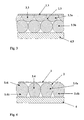
- the Fig. 1 shows in cross section a composite armor plate with two superimposed layers of rod-shaped high-hardness elements 3.1, which are arranged in a manner not shown one behind the other in rows.
- the outer cover layer 1.1 is glued to the rod-shaped elements 3.1 and a cover layer 4.1 by means of a potting 2.1 made of epoxy resin.
- the rod-shaped elements 3.1 are made of alumina ceramic and have a hexagonal cross-section.
- the rod-shaped elements 3.1 are arranged in a manner not shown within a row one behind the other, that the joints between the elements of a series of rod-shaped elements 3.1a of the upper layer with respect to the joints of an adjacent row of rod-shaped elements 3.1 b of the lower layer are arranged offset.
- the Fig. 2 shows in cross section a composite armor plate with two superimposed layers of rod-shaped high-hardness elements 3.2.
- the arrangement of the rod-shaped elements 3.2 corresponds to the arrangement according to Fig. 1 ,
- the rod-shaped elements 3.2 have a triangular cross-section.
- Analogous to Fig. 1 the outer cover layer 1.2 is glued to the rod-shaped elements 3.2 and a final layer 4.2 by means of a potting compound 2.2.
- the Fig. 3 shows in cross section a composite armor plate with two superimposed layers of rod-shaped high-hardness elements 3.3.
- the arrangement of the rod-shaped elements 3.3 corresponds to the arrangement according to Fig. 1 ,
- the upper rows 3.3a of the rod-shaped elements 3.3 have a different geometry than the lower rows 3.3b of the rod-shaped elements, whereby a smoothest possible outer surface is realized.
- Analogous to Fig. 1 the outer cover layer 1.3 is glued to the rod-shaped elements 3.3 and a finishing layer 4.3 by means of a potting compound 2.3.
- the Fig. 4 shows in cross section a composite armor plate with only one layer of rod-shaped high-hardness elements 3.4, which are arranged in a manner not shown one behind the other in rows.
- the elements 3.4 have an upper rounded portion 3.4i and a lower angular portion 3.4ii.
- the outer cover layer 1.4 is glued to the rod-shaped elements 3.4 and a final layer 4.4 by means of a potting compound 2.4.
- the rod-shaped elements 3.4 are arranged in a manner not shown within a row one behind the other, that the joints between the elements of a series of rod-shaped elements 3.4a are arranged offset with respect to the joints of an adjacent row of rod-shaped elements 3.4b the same situation.
- the Fig. 5 shows in longitudinal section a composite armor plate with an outer cover layer 1.5, a cover layer 4.5 and two superimposed rows of rod-shaped high-hardness elements 3.5. It is the offset of the joints of the longitudinal division between the upper row 3.5a of rod-shaped elements and the lower row shown 3.5b.
- the end faces 5.5 of the rod-shaped elements 3.5 are designed as a flat surface, wherein the plane assumes an oblique position with respect to the axial direction of the rod-shaped elements. Between the end faces of two adjacent elements 3.5 is an air gap 10.5.
- the Fig. 6 shows analogously to Fig. 5 a composite armor plate in longitudinal section with an outer cover layer 1.6, a final layer 4.6 and two superimposed rows of rod-shaped high-hardness elements 3.6. It is the offset of the joints of the longitudinal division between the upper row 3.6a of rod-shaped elements and the lower row 3.6b shown.
- the rod-shaped elements 3.6 have a convex end face 5.6a at one end and a concave end face 5.6b at the other end.
- the Fig. 7 shows analogously to Fig. 5 a composite armor plate in longitudinal section with an outer cover layer 1.7, a finishing layer 4.7 and two superposed rows of rod-shaped high-hardness elements 3.7. It is the offset of the joints of the longitudinal division between the upper row 3.7a of rod-shaped elements and the lower row 3.7b shown.
- the rod-shaped elements 3.7 have a conically outwardly directed end face 5.7a at one end and a conically inwardly directed end face 5.7b at the other end.
- the Fig. 8 shows in cross section a composite armor plate with two superimposed layers of rod-shaped high-hardness elements 3.8.
- the arrangement of the rod-shaped elements 3.8 corresponds to the arrangement according to Fig. 1 ,
- the rod-shaped elements 3.8 have a round cross section.
- Analogous to Fig. 1 the outer cover layer 1.8 is glued to the rod-shaped elements 3.8 and a final layer 4.8 by means of a potting compound 2.8.
- Between the rod-shaped elements 3.8 is a damping material in the form of threads 6.8a and 6.8b bands.
- the Fig. 9 shows analogously to Fig. 5 a composite armor plate in longitudinal section with an outer cover layer 1.9, a finishing layer 4.9 and two superimposed rows of rod-shaped high-hardness elements 3.9. It is the offset of the joints of the longitudinal division between the upper row 3.9a of rod-shaped elements and the lower row shown 3.9b. Between the end faces 5.9 of the rod-shaped elements 3.9 a damping material in the form of threads 7.9 is introduced.
- the Fig. 10 shows in cross-section a composite armor plate with two superimposed layers of rod-shaped high-hardness elements 3.10, which are arranged in a manner not shown one behind the other in rows.
- the rod-shaped elements 3.10 have a round cross-section.
- the outer cover layer 1.10 is glued to the rod-shaped elements 3.10 and a damping intermediate layer 8.10 by means of a potting compound 2.10.
- the rod-shaped elements 3.10 are arranged in a manner not shown in a row one behind the other, that the joints between the elements of a series of rod-shaped elements 3.10a of the upper layer are arranged offset with respect to the joints of an adjacent row of rod-shaped elements 3.10b of the lower layer.
- the composite armor plate is attached via a damping intermediate layer 8.10 with a metal structure 9.10 of a housing to be protected.
- the Fig. 11 shows in cross section a composite armor plate with two superposed layers of rod-shaped high-hardness elements 3.11, which are arranged in a manner not shown one behind the other in rows.
- the rod-shaped elements 3.11 have a round cross-section.
- the outer cover layer 1.11 is glued to the rod-shaped elements 3.11 by means of a potting compound 2.11.
- the rod-shaped elements 3.11 are arranged in a manner not shown within a row one behind the other, that the joints between the elements of a row of rod-shaped elements 3.11a of the upper layer are arranged offset with respect to the joints of an adjacent row of rod-shaped elements 3.11b of the lower layer.
- the composite armor plate is attached directly to a metal structure 9.11 of a housing to be protected. On a damping intermediate layer, as in Fig. 10 shown, can be omitted because the potting compound has a sufficiently large layer thickness in this area.
- the invention is not limited to the illustrated embodiments.
- the invention also includes, according to the patent claims, combinations of the illustrated exemplary embodiments as well as further embodiments, not shown.
Landscapes
- Engineering & Computer Science (AREA)
- General Engineering & Computer Science (AREA)
- Aiming, Guidance, Guns With A Light Source, Armor, Camouflage, And Targets (AREA)
- Braking Arrangements (AREA)
Applications Claiming Priority (2)
| Application Number | Priority Date | Filing Date | Title |
|---|---|---|---|
| DE102005050981A DE102005050981A1 (de) | 2005-10-25 | 2005-10-25 | Verbundpanzerplatte |
| EP06791360A EP1941229B1 (fr) | 2005-10-25 | 2006-09-08 | Plaque composite de blindage |
Related Parent Applications (2)
| Application Number | Title | Priority Date | Filing Date |
|---|---|---|---|
| EP06791360.8 Division | 2006-09-08 | ||
| EP06791360A Division EP1941229B1 (fr) | 2005-10-25 | 2006-09-08 | Plaque composite de blindage |
Publications (2)
| Publication Number | Publication Date |
|---|---|
| EP2072945A1 true EP2072945A1 (fr) | 2009-06-24 |
| EP2072945B1 EP2072945B1 (fr) | 2011-01-26 |
Family
ID=37487560
Family Applications (2)
| Application Number | Title | Priority Date | Filing Date |
|---|---|---|---|
| EP06791360A Active EP1941229B1 (fr) | 2005-10-25 | 2006-09-08 | Plaque composite de blindage |
| EP09002896A Active EP2072945B1 (fr) | 2005-10-25 | 2006-09-08 | Plaque de blindage composite |
Family Applications Before (1)
| Application Number | Title | Priority Date | Filing Date |
|---|---|---|---|
| EP06791360A Active EP1941229B1 (fr) | 2005-10-25 | 2006-09-08 | Plaque composite de blindage |
Country Status (5)
| Country | Link |
|---|---|
| EP (2) | EP1941229B1 (fr) |
| AT (1) | ATE497141T1 (fr) |
| DE (3) | DE102005050981A1 (fr) |
| ES (1) | ES2359606T3 (fr) |
| WO (1) | WO2007048370A1 (fr) |
Families Citing this family (14)
| Publication number | Priority date | Publication date | Assignee | Title |
|---|---|---|---|---|
| EP1737653A4 (fr) * | 2004-04-23 | 2009-04-01 | Us Navy | Armature comprenant un elastomere durcissant sous sollicitations |
| AT504712A1 (de) * | 2006-12-21 | 2008-07-15 | Steyr Daimler Puch Ag | Verfahren zur herstellung einer zusatzpanzerung |
| DE102007019392B4 (de) * | 2007-04-23 | 2010-09-30 | Krauss-Maffei Wegmann Gmbh & Co. Kg | Verbundpanzerungselement |
| DE102007050658B4 (de) | 2007-10-24 | 2010-02-11 | Krauss-Maffei Wegmann Gmbh & Co. Kg | Flächiges Verbundpanzerungselement |
| DE102007050660B4 (de) | 2007-10-24 | 2010-03-25 | Krauss-Maffei Wegmann Gmbh & Co. Kg | Flächiges Verbundpanzerungselement |
| IL195090A0 (en) | 2008-11-04 | 2009-09-22 | Gigi Simovich | A method and a device for pre-stressed armor |
| EP2233877A1 (fr) * | 2009-03-27 | 2010-09-29 | M.E.RIN S.r.l. | Elément balistique et structure renforcée incorporant un tel élément balistique |
| DE102009023225A1 (de) | 2009-05-29 | 2010-12-09 | Rheinmetall Landsysteme Gmbh | Minensichere Komponentenlagerung |
| DE102009029814C5 (de) | 2009-06-18 | 2017-01-26 | Rheinmetall Landsysteme Gmbh | Vorrichtung zur Energieabsorption und Verwendung der Vorrichtung als Minen-Schutzvorrichtung oder Aufpralldämpfer für ein Kraftfahrzeug |
| DE102010000649B4 (de) | 2010-03-05 | 2013-04-25 | Krauss-Maffei Wegmann Gmbh & Co. Kg | Verfahren zur Instandsetzung eines Verbundpanzerungselements sowie Reparatur-Set zur Durchführung der Instandsetzung |
| DE102010000648B4 (de) | 2010-03-05 | 2024-09-19 | Knds Deutschland Gmbh & Co. Kg | Verbundpanzerungselement zum Schutz vor Geschossen |
| DE202011101637U1 (de) * | 2011-06-01 | 2012-09-05 | Fct Ingenieurkeramik Gmbh | Mehrschichtiger Ballistikschutz |
| PL236456B1 (pl) * | 2018-03-08 | 2021-01-25 | Ht Guard Spolka Z Ograniczona Odpowiedzialnoscia | Materiał balistyczny |
| FR3160765A1 (fr) * | 2024-03-26 | 2025-10-03 | Pangolin | Plaque de protection balistique |
Citations (7)
| Publication number | Priority date | Publication date | Assignee | Title |
|---|---|---|---|---|
| DE1578324A1 (de) | 1965-04-26 | 1970-01-02 | Aerojet General Co | Panzerung |
| US3573150A (en) * | 1968-07-24 | 1971-03-30 | Us Army | Transparent armor |
| GB1260111A (en) * | 1964-07-07 | 1972-01-12 | Rolls Royce | Structure for resisting projectiles |
| EP0041271A1 (fr) * | 1980-06-02 | 1981-12-09 | Alvin Eugene Gorum | Blindage composite à base de matériaux céramiques |
| DE3134341A1 (de) * | 1980-09-02 | 1982-05-13 | Schweizerische Eidgenossenschaft vertreten durch die Eidg. Munitionsfabrik Thun der Gruppe für Rüstungsdienste, 3603 Thun | Verbundpanzerung |
| FR2559254A1 (fr) | 1984-02-02 | 1985-08-09 | Picard | Blindage resistant au percage et son procede de fabrication |
| EP0967453A1 (fr) * | 1998-06-25 | 1999-12-29 | Armortec Incorporated | Matériau flexible résistant à l'impact |
Family Cites Families (4)
| Publication number | Priority date | Publication date | Assignee | Title |
|---|---|---|---|---|
| US1216538A (en) * | 1917-01-08 | 1917-02-20 | Gesesellschaft Fuer Drahtlose Telegraphie M B H | Means for producing electrical oscillations. |
| DE4230073C2 (de) * | 1992-09-09 | 1996-04-04 | Rheinmetall Ind Gmbh | Passive Schutzanordnung |
| DE19653218C1 (de) * | 1996-12-19 | 1998-07-30 | Bps Bowas Protection Systems G | Durchschußhemmendes und schlagresistentes Schichtmaterial |
| US6532857B1 (en) * | 2000-05-12 | 2003-03-18 | Ceradyne, Inc. | Ceramic array armor |
-
2005
- 2005-10-25 DE DE102005050981A patent/DE102005050981A1/de not_active Withdrawn
-
2006
- 2006-09-08 WO PCT/DE2006/001568 patent/WO2007048370A1/fr not_active Ceased
- 2006-09-08 ES ES09002896T patent/ES2359606T3/es active Active
- 2006-09-08 EP EP06791360A patent/EP1941229B1/fr active Active
- 2006-09-08 DE DE502006008835T patent/DE502006008835D1/de active Active
- 2006-09-08 AT AT09002896T patent/ATE497141T1/de active
- 2006-09-08 DE DE502006007194T patent/DE502006007194D1/de active Active
- 2006-09-08 EP EP09002896A patent/EP2072945B1/fr active Active
Patent Citations (7)
| Publication number | Priority date | Publication date | Assignee | Title |
|---|---|---|---|---|
| GB1260111A (en) * | 1964-07-07 | 1972-01-12 | Rolls Royce | Structure for resisting projectiles |
| DE1578324A1 (de) | 1965-04-26 | 1970-01-02 | Aerojet General Co | Panzerung |
| US3573150A (en) * | 1968-07-24 | 1971-03-30 | Us Army | Transparent armor |
| EP0041271A1 (fr) * | 1980-06-02 | 1981-12-09 | Alvin Eugene Gorum | Blindage composite à base de matériaux céramiques |
| DE3134341A1 (de) * | 1980-09-02 | 1982-05-13 | Schweizerische Eidgenossenschaft vertreten durch die Eidg. Munitionsfabrik Thun der Gruppe für Rüstungsdienste, 3603 Thun | Verbundpanzerung |
| FR2559254A1 (fr) | 1984-02-02 | 1985-08-09 | Picard | Blindage resistant au percage et son procede de fabrication |
| EP0967453A1 (fr) * | 1998-06-25 | 1999-12-29 | Armortec Incorporated | Matériau flexible résistant à l'impact |
Also Published As
| Publication number | Publication date |
|---|---|
| ES2359606T3 (es) | 2011-05-25 |
| EP1941229B1 (fr) | 2010-06-09 |
| EP2072945B1 (fr) | 2011-01-26 |
| DE502006007194D1 (de) | 2010-07-22 |
| ATE497141T1 (de) | 2011-02-15 |
| DE102005050981A1 (de) | 2007-04-26 |
| EP1941229A1 (fr) | 2008-07-09 |
| DE502006008835D1 (de) | 2011-03-10 |
| WO2007048370A1 (fr) | 2007-05-03 |
Similar Documents
| Publication | Publication Date | Title |
|---|---|---|
| EP1985961B1 (fr) | Elément de blindage composite | |
| EP1949017B1 (fr) | Élément de blindage composite et élément de corps actif pour l'insertion dans un élément de blindage composite | |
| EP1941229B1 (fr) | Plaque composite de blindage | |
| DE60028919T2 (de) | Ballistische Panzerplatte | |
| DE3426457A1 (de) | Geschosshemmendes flaechengebilde | |
| EP1705453B1 (fr) | Plaque de blindage composite pour protéger véhicules et bâtiments contre projectiles avec energie cinétique élevée | |
| WO2020250147A1 (fr) | Plaque de blindage, composite de plaques de blindage et blindage | |
| EP2053340B1 (fr) | Elément de blindage composite plat | |
| EP3697566A1 (fr) | Pièce structurale de renfort | |
| EP3055639B1 (fr) | Élément de protection équipé d'une couche de découplage | |
| DE102009034941A1 (de) | Fahrzeugpanzerung | |
| EP2363682B1 (fr) | Procédé de réparation d'un élément de blindage composite et kit de réparation destiné à la réalisation de la réparation | |
| EP2053339B1 (fr) | Elément de blindage composite plat | |
| DE102022100599A1 (de) | Panzerungsplatte, Panzerungsplattenverbund und Panzerung | |
| DE102009057052B4 (de) | Schüttgutförmiges Material sowie ein derartiges Material enthaltendes Schutzmodul zum Schutz gegen militärische Bedrohungen | |
| DE102007002210A1 (de) | Platte für eine schussfeste Panzerung | |
| DE102024000944A1 (de) | Laminiertes Verbundbauteil, Fahrzeugkarosseriebauteil, Verfahren zur Herstellung eines solchen Verbundbauteils und Verwendung eines solchen Verbundbauteils | |
| EP2363683A2 (fr) | Elément de blindage composite, notamment plaque de blindage composite, pour la protection contre des projectiles |
Legal Events
| Date | Code | Title | Description |
|---|---|---|---|
| PUAI | Public reference made under article 153(3) epc to a published international application that has entered the european phase |
Free format text: ORIGINAL CODE: 0009012 |
|
| AC | Divisional application: reference to earlier application |
Ref document number: 1941229 Country of ref document: EP Kind code of ref document: P |
|
| AK | Designated contracting states |
Kind code of ref document: A1 Designated state(s): AT BE BG CH CY CZ DE DK EE ES FI FR GB GR HU IE IS IT LI LT LU LV MC NL PL PT RO SE SI SK TR |
|
| AX | Request for extension of the european patent |
Extension state: AL BA HR MK RS |
|
| 17P | Request for examination filed |
Effective date: 20091120 |
|
| AKX | Designation fees paid |
Designated state(s): AT BE BG CH CY CZ DE DK EE ES FI FR GB GR HU IE IS IT LI LT LU LV MC NL PL PT RO SE SI SK TR |
|
| GRAP | Despatch of communication of intention to grant a patent |
Free format text: ORIGINAL CODE: EPIDOSNIGR1 |
|
| RTI1 | Title (correction) |
Free format text: COMPOSITE ARMOUR PLATE |
|
| GRAS | Grant fee paid |
Free format text: ORIGINAL CODE: EPIDOSNIGR3 |
|
| GRAA | (expected) grant |
Free format text: ORIGINAL CODE: 0009210 |
|
| AC | Divisional application: reference to earlier application |
Ref document number: 1941229 Country of ref document: EP Kind code of ref document: P |
|
| AK | Designated contracting states |
Kind code of ref document: B1 Designated state(s): AT BE BG CH CY CZ DE DK EE ES FI FR GB GR HU IE IS IT LI LT LU LV MC NL PL PT RO SE SI SK TR |
|
| REG | Reference to a national code |
Ref country code: GB Ref legal event code: FG4D Free format text: NOT ENGLISH |
|
| REG | Reference to a national code |
Ref country code: CH Ref legal event code: EP |
|
| REG | Reference to a national code |
Ref country code: IE Ref legal event code: FG4D Free format text: LANGUAGE OF EP DOCUMENT: GERMAN |
|
| REF | Corresponds to: |
Ref document number: 502006008835 Country of ref document: DE Date of ref document: 20110310 Kind code of ref document: P |
|
| REG | Reference to a national code |
Ref country code: DE Ref legal event code: R096 Ref document number: 502006008835 Country of ref document: DE Effective date: 20110310 |
|
| REG | Reference to a national code |
Ref country code: NL Ref legal event code: T3 |
|
| REG | Reference to a national code |
Ref country code: ES Ref legal event code: FG2A Ref document number: 2359606 Country of ref document: ES Kind code of ref document: T3 Effective date: 20110525 |
|
| LTIE | Lt: invalidation of european patent or patent extension |
Effective date: 20110126 |
|
| PG25 | Lapsed in a contracting state [announced via postgrant information from national office to epo] |
Ref country code: GR Free format text: LAPSE BECAUSE OF FAILURE TO SUBMIT A TRANSLATION OF THE DESCRIPTION OR TO PAY THE FEE WITHIN THE PRESCRIBED TIME-LIMIT Effective date: 20110427 Ref country code: LV Free format text: LAPSE BECAUSE OF FAILURE TO SUBMIT A TRANSLATION OF THE DESCRIPTION OR TO PAY THE FEE WITHIN THE PRESCRIBED TIME-LIMIT Effective date: 20110126 Ref country code: SE Free format text: LAPSE BECAUSE OF FAILURE TO SUBMIT A TRANSLATION OF THE DESCRIPTION OR TO PAY THE FEE WITHIN THE PRESCRIBED TIME-LIMIT Effective date: 20110126 Ref country code: LT Free format text: LAPSE BECAUSE OF FAILURE TO SUBMIT A TRANSLATION OF THE DESCRIPTION OR TO PAY THE FEE WITHIN THE PRESCRIBED TIME-LIMIT Effective date: 20110126 Ref country code: PT Free format text: LAPSE BECAUSE OF FAILURE TO SUBMIT A TRANSLATION OF THE DESCRIPTION OR TO PAY THE FEE WITHIN THE PRESCRIBED TIME-LIMIT Effective date: 20110526 |
|
| REG | Reference to a national code |
Ref country code: IE Ref legal event code: FD4D |
|
| PG25 | Lapsed in a contracting state [announced via postgrant information from national office to epo] |
Ref country code: SI Free format text: LAPSE BECAUSE OF FAILURE TO SUBMIT A TRANSLATION OF THE DESCRIPTION OR TO PAY THE FEE WITHIN THE PRESCRIBED TIME-LIMIT Effective date: 20110126 Ref country code: PL Free format text: LAPSE BECAUSE OF FAILURE TO SUBMIT A TRANSLATION OF THE DESCRIPTION OR TO PAY THE FEE WITHIN THE PRESCRIBED TIME-LIMIT Effective date: 20110126 Ref country code: FI Free format text: LAPSE BECAUSE OF FAILURE TO SUBMIT A TRANSLATION OF THE DESCRIPTION OR TO PAY THE FEE WITHIN THE PRESCRIBED TIME-LIMIT Effective date: 20110126 Ref country code: CY Free format text: LAPSE BECAUSE OF FAILURE TO SUBMIT A TRANSLATION OF THE DESCRIPTION OR TO PAY THE FEE WITHIN THE PRESCRIBED TIME-LIMIT Effective date: 20110126 Ref country code: BG Free format text: LAPSE BECAUSE OF FAILURE TO SUBMIT A TRANSLATION OF THE DESCRIPTION OR TO PAY THE FEE WITHIN THE PRESCRIBED TIME-LIMIT Effective date: 20110426 |
|
| PG25 | Lapsed in a contracting state [announced via postgrant information from national office to epo] |
Ref country code: EE Free format text: LAPSE BECAUSE OF FAILURE TO SUBMIT A TRANSLATION OF THE DESCRIPTION OR TO PAY THE FEE WITHIN THE PRESCRIBED TIME-LIMIT Effective date: 20110126 Ref country code: DK Free format text: LAPSE BECAUSE OF FAILURE TO SUBMIT A TRANSLATION OF THE DESCRIPTION OR TO PAY THE FEE WITHIN THE PRESCRIBED TIME-LIMIT Effective date: 20110126 Ref country code: IE Free format text: LAPSE BECAUSE OF FAILURE TO SUBMIT A TRANSLATION OF THE DESCRIPTION OR TO PAY THE FEE WITHIN THE PRESCRIBED TIME-LIMIT Effective date: 20110126 |
|
| PG25 | Lapsed in a contracting state [announced via postgrant information from national office to epo] |
Ref country code: RO Free format text: LAPSE BECAUSE OF FAILURE TO SUBMIT A TRANSLATION OF THE DESCRIPTION OR TO PAY THE FEE WITHIN THE PRESCRIBED TIME-LIMIT Effective date: 20110126 Ref country code: SK Free format text: LAPSE BECAUSE OF FAILURE TO SUBMIT A TRANSLATION OF THE DESCRIPTION OR TO PAY THE FEE WITHIN THE PRESCRIBED TIME-LIMIT Effective date: 20110126 |
|
| PLBE | No opposition filed within time limit |
Free format text: ORIGINAL CODE: 0009261 |
|
| STAA | Information on the status of an ep patent application or granted ep patent |
Free format text: STATUS: NO OPPOSITION FILED WITHIN TIME LIMIT |
|
| 26N | No opposition filed |
Effective date: 20111027 |
|
| REG | Reference to a national code |
Ref country code: DE Ref legal event code: R097 Ref document number: 502006008835 Country of ref document: DE Effective date: 20111027 |
|
| PG25 | Lapsed in a contracting state [announced via postgrant information from national office to epo] |
Ref country code: MC Free format text: LAPSE BECAUSE OF NON-PAYMENT OF DUE FEES Effective date: 20110930 |
|
| REG | Reference to a national code |
Ref country code: CH Ref legal event code: PL |
|
| PG25 | Lapsed in a contracting state [announced via postgrant information from national office to epo] |
Ref country code: CH Free format text: LAPSE BECAUSE OF NON-PAYMENT OF DUE FEES Effective date: 20110930 Ref country code: LI Free format text: LAPSE BECAUSE OF NON-PAYMENT OF DUE FEES Effective date: 20110930 |
|
| PG25 | Lapsed in a contracting state [announced via postgrant information from national office to epo] |
Ref country code: LU Free format text: LAPSE BECAUSE OF NON-PAYMENT OF DUE FEES Effective date: 20110908 |
|
| PG25 | Lapsed in a contracting state [announced via postgrant information from national office to epo] |
Ref country code: IS Free format text: LAPSE BECAUSE OF FAILURE TO SUBMIT A TRANSLATION OF THE DESCRIPTION OR TO PAY THE FEE WITHIN THE PRESCRIBED TIME-LIMIT Effective date: 20110126 |
|
| PG25 | Lapsed in a contracting state [announced via postgrant information from national office to epo] |
Ref country code: TR Free format text: LAPSE BECAUSE OF FAILURE TO SUBMIT A TRANSLATION OF THE DESCRIPTION OR TO PAY THE FEE WITHIN THE PRESCRIBED TIME-LIMIT Effective date: 20110126 |
|
| PG25 | Lapsed in a contracting state [announced via postgrant information from national office to epo] |
Ref country code: HU Free format text: LAPSE BECAUSE OF FAILURE TO SUBMIT A TRANSLATION OF THE DESCRIPTION OR TO PAY THE FEE WITHIN THE PRESCRIBED TIME-LIMIT Effective date: 20110126 |
|
| REG | Reference to a national code |
Ref country code: FR Ref legal event code: PLFP Year of fee payment: 11 |
|
| REG | Reference to a national code |
Ref country code: FR Ref legal event code: PLFP Year of fee payment: 12 |
|
| REG | Reference to a national code |
Ref country code: FR Ref legal event code: PLFP Year of fee payment: 13 |
|
| PGFP | Annual fee paid to national office [announced via postgrant information from national office to epo] |
Ref country code: FR Payment date: 20180921 Year of fee payment: 13 Ref country code: IT Payment date: 20180921 Year of fee payment: 13 |
|
| PGFP | Annual fee paid to national office [announced via postgrant information from national office to epo] |
Ref country code: NL Payment date: 20180920 Year of fee payment: 13 Ref country code: CZ Payment date: 20180903 Year of fee payment: 13 Ref country code: GB Payment date: 20180924 Year of fee payment: 13 Ref country code: BE Payment date: 20180920 Year of fee payment: 13 Ref country code: AT Payment date: 20180918 Year of fee payment: 13 |
|
| PGFP | Annual fee paid to national office [announced via postgrant information from national office to epo] |
Ref country code: ES Payment date: 20181024 Year of fee payment: 13 |
|
| REG | Reference to a national code |
Ref country code: NL Ref legal event code: MM Effective date: 20191001 |
|
| PG25 | Lapsed in a contracting state [announced via postgrant information from national office to epo] |
Ref country code: CZ Free format text: LAPSE BECAUSE OF NON-PAYMENT OF DUE FEES Effective date: 20190908 |
|
| PG25 | Lapsed in a contracting state [announced via postgrant information from national office to epo] |
Ref country code: NL Free format text: LAPSE BECAUSE OF NON-PAYMENT OF DUE FEES Effective date: 20191001 |
|
| REG | Reference to a national code |
Ref country code: BE Ref legal event code: MM Effective date: 20190930 |
|
| REG | Reference to a national code |
Ref country code: AT Ref legal event code: MM01 Ref document number: 497141 Country of ref document: AT Kind code of ref document: T Effective date: 20190908 |
|
| PG25 | Lapsed in a contracting state [announced via postgrant information from national office to epo] |
Ref country code: BE Free format text: LAPSE BECAUSE OF NON-PAYMENT OF DUE FEES Effective date: 20190930 Ref country code: IT Free format text: LAPSE BECAUSE OF NON-PAYMENT OF DUE FEES Effective date: 20190908 |
|
| GBPC | Gb: european patent ceased through non-payment of renewal fee |
Effective date: 20190908 |
|
| PG25 | Lapsed in a contracting state [announced via postgrant information from national office to epo] |
Ref country code: FR Free format text: LAPSE BECAUSE OF NON-PAYMENT OF DUE FEES Effective date: 20190930 Ref country code: GB Free format text: LAPSE BECAUSE OF NON-PAYMENT OF DUE FEES Effective date: 20190908 |
|
| PG25 | Lapsed in a contracting state [announced via postgrant information from national office to epo] |
Ref country code: AT Free format text: LAPSE BECAUSE OF NON-PAYMENT OF DUE FEES Effective date: 20190908 |
|
| REG | Reference to a national code |
Ref country code: ES Ref legal event code: FD2A Effective date: 20210127 |
|
| PG25 | Lapsed in a contracting state [announced via postgrant information from national office to epo] |
Ref country code: ES Free format text: LAPSE BECAUSE OF NON-PAYMENT OF DUE FEES Effective date: 20190909 |
|
| P01 | Opt-out of the competence of the unified patent court (upc) registered |
Effective date: 20230517 |
|
| REG | Reference to a national code |
Ref country code: DE Ref legal event code: R081 Ref document number: 502006008835 Country of ref document: DE Owner name: KNDS DEUTSCHLAND GMBH & CO. KG, DE Free format text: FORMER OWNER: KRAUSS-MAFFEI WEGMANN GMBH & CO. KG, 80997 MUENCHEN, DE |
|
| PGFP | Annual fee paid to national office [announced via postgrant information from national office to epo] |
Ref country code: DE Payment date: 20240930 Year of fee payment: 19 |