EP2072956A2 - Flugmanagementsysteme und -verfahren zur Verwendung mit einem Luftfahrzeug - Google Patents
Flugmanagementsysteme und -verfahren zur Verwendung mit einem Luftfahrzeug Download PDFInfo
- Publication number
- EP2072956A2 EP2072956A2 EP08171719A EP08171719A EP2072956A2 EP 2072956 A2 EP2072956 A2 EP 2072956A2 EP 08171719 A EP08171719 A EP 08171719A EP 08171719 A EP08171719 A EP 08171719A EP 2072956 A2 EP2072956 A2 EP 2072956A2
- Authority
- EP
- European Patent Office
- Prior art keywords
- display
- flight
- processor
- mode
- aerial vehicle
- Prior art date
- Legal status (The legal status is an assumption and is not a legal conclusion. Google has not performed a legal analysis and makes no representation as to the accuracy of the status listed.)
- Withdrawn
Links
Images



Classifications
-
- G—PHYSICS
- G01—MEASURING; TESTING
- G01C—MEASURING DISTANCES, LEVELS OR BEARINGS; SURVEYING; NAVIGATION; GYROSCOPIC INSTRUMENTS; PHOTOGRAMMETRY OR VIDEOGRAMMETRY
- G01C23/00—Combined instruments indicating more than one navigational value, e.g. for aircraft; Combined measuring devices for measuring two or more variables of movement, e.g. distance, speed or acceleration
- G01C23/005—Flight directors
Definitions
- the present application pertains to flight management systems and methods, and, more particularly, to improved systems and methods for cockpit display of flight route information.
- Such systems and methods can be used, by way of example, for enhanced display of flight paths and navigational indicators, e.g., during take-off.
- Flight management systems facilitate an aircraft pilot's duties by displaying flight paths and/or other navigational indicators directing the pilot to a pre-selected destination or waypoint.
- Typical prior art systems allow a pilot to key in or otherwise input a destination location (e.g., "DTW ILS RWY 22L,” indicating the Detroit airport, ILS approach to runway 22L) and one or more waypoints (e.g., "LWM - VOR,” indicating the visual omnirange beacon in Lawrence, Massachusetts).
- DTW ILS RWY 22L indicating the Detroit airport, ILS approach to runway 22L
- waypoints e.g., "LWM - VOR,” indicating the visual omnirange beacon in Lawrence, Massachusetts.
- the pilot enters that information before taxiing the aircraft for take-off.
- the systems use the information, along with positional data from an on-board navigation system, e.g., a Global Positioning System (GPS), to determine and display bearing and altitude indicators (e.g., arrows, pointers, etc.) showing the appropriate direction of flight.
- GPS Global Positioning System
- More advanced systems additionally display graphical representations of flight paths guiding the pilot at least partially to the waypoint or other destination.
- These displays can include a two-dimensional (2D) depiction of a flight path against a map or other representation of geography over which flight will occur.
- the path is displayed in three dimensions (3D) and includes not just representations of topography but also airspace.
- a problem with prior art systems is that they have limited practical use during take-off. For example, it is quite common that a flight path or navigational indicator generated before the aircraft taxies down the runway and lifts off into the air will not be useful after take-off, when the craft's location, heading and altitude have changed.
- pilots have become accustomed to programming waypoint (and other destination) information into their crafts' flight management systems before take-off and, then, to re-programming that information into the systems after take-off in order to insure that displayed flight paths and navigational indicators are accurate.
- Yet further aspects of the invention are to provide such methods and systems for improved display of flight indicators.
- Still other objects of the invention are to provide such methods and systems as can be readily understood by pilots, copilots, navigators and others.
- Such systems can include a processor that drives a display to generate a two-dimensional (2D) or three-dimensional (3D) depiction of flight path.
- the processor drives the display to generate a flexible highway-in-the-sky (HITS) flight path having an endpoint that is fixed to a destination (e.g., specified by the pilot) and having an origin that is fixed to the craft and that moves with it (e.g., a path that "stays" with the vehicle).
- HITS flexible highway-in-the-sky
- the processor drives the display to generate a depiction of a fixed HITS flight path that has a fixed, non-moving origin and destination and that do not move relative to the craft.
- the processor enters the first mode of operation during take-off procedures. In further related aspects of the invention, the processor switches from the first mode to the second mode once a first waypoint or other destination has been reached.
- the processor switches from the first mode to the second mode when (i) the aircraft reaches the first waypoint (or other destination), (ii) the craft comes within a predetermined variance in distance to and/or bearing of that waypoint (or other destination), and/or (iii) flight conditions, geography, air traffic, air space restrictions, the craft's performance capabilities or other conditions dictate (for safety or other reasons) that the flight management system switch from the first to the second mode.
- a flight management system as described above can display a flexible HITS flight path during aircraft take-off and, particularly, as the craft turns during climbout. If the pilot encounters conflicting traffic and temporarily stops the turn or is otherwise delayed in reaching his first waypoint (or other destination), the flight management system continually updates the flexible HITS display, calculating a successive series of best routings from the craft's changing location to the first waypoint (or other destination). This saves the pilot from having to repeatedly reprogram the flight management system during the climb-out procedure in order to find the best path to the waypoint (or other destination).
- the flight management system switches to a fixed HITS display when the craft (i) reaches the waypoint (or other destination) - or comes within a predetermined distance of and/or bearing to that waypoint (or other destination), and/or (ii) flight conditions, geography, air traffic, air space restrictions, the craft's performance capabilities or other conditions dictate (for safety or other reasons) that the flight management system switch from the first to the second mode (i.e., from flexible to a fixed HITS display).
- the processor drives the display to generate the 2D or 3D depiction of the flight path against a map or other representation of topography over which flight will occur. In further related aspects of the invention, the processor drives the display to generate the 3D depiction of the flight path against a three-dimensional representation of topography and airspace.
- the flexible HITS flight path is generated as a function of at least a (i) current location of the aerial vehicle, and (ii) a destination location entered into the processor by a pilot, e.g., prior to take-off.
- Such systems can include a processor that drives a display to generate textual and/or two-dimensional or three-dimensional graphical depictions of such indicators.
- the processor drives the display to generate indicators that it automatically updates relative to a current location of the aerial vehicle.
- the processor drives the display to generate static indicators of bearing (and/or altitude change) that, once determined, remain fixed (regardless of movement of the craft) until recalculated at request of the pilot.
- the processor enters the first mode of operation during take-off procedures.
- the processor switches from the first mode to the second mode (i) when the craft reaches the first waypoint (or other destination), (ii) when the aircraft comes within a predetermined variance of distance to and/or bearing of that waypoint (or other destination), and/or (iii) flight conditions, geography, air traffic, air space restrictions, the craft's performance capabilities or other conditions dictate (for safety or other reasons) that the flight management system switch from the first to the second mode.
- a flight management system as described above can display an auto-updating bearing indicator as an aircraft climbs out of the airport in a climbing right turn.
- the processor can continue updating the indicator until the aircraft's track is within 15 degrees of the bearing to the first waypoint, at which time the processor switches display to the second mode, displaying a fixed indicator until the pilot reprograms a (new) destination into the system.
- the processor drives the display to generate depictions of both the aforementioned HITS flight path representations and bearing, altitude change, or other navigational indicators, all in a single display window.
- Still other aspects of the invention provide methods paralleling the operations described above.
- FIG. 1 depicts an exemplary navigational system for use in an aircraft according to one practice of the invention.
- the system 100 includes a display 120 coupled to a processing unit 110, both constructed and operated in accord with flight navigational systems known in the art (for example, in accord with the VistaNavTM multifunction flight display, sold by the assignee hereof, Mercury Computer Systems Inc., of Chelmsford, Massachusetts) - albeit as adapted in accord with the teachings hereof.
- flight navigational systems known in the art (for example, in accord with the VistaNavTM multifunction flight display, sold by the assignee hereof, Mercury Computer Systems Inc., of Chelmsford, Massachusetts) - albeit as adapted in accord with the teachings hereof.
- Illustrated processing unit 110 comprises an input/output (I/O) section 111, a central processing unit (CPU) 112, dynamic memory (RAM) 113 and a static store 114, all constructed, interconnected and operated in the conventional manner of general purpose and/or embedded digital data processing devices used in flight management systems known in the art - again, as adapted in accord with the teachings hereof.
- I/O input/output
- CPU central processing unit
- RAM dynamic memory
- static store 114 static store
- Static store 114 comprises a CD-ROM, DVD, hard disk and/or other long-term storage device of the type known in the art. This can hold software instructions governing operation of the processing unit 110, as well as data reflecting operational capabilities of the aircraft with which the system 100 is used.
- the latter can include (i) data reflecting theoretical capabilities of the aircraft, e.g., based on "book" values of aircraft lift, weight, drag, glide-ratio, and so forth, (ii) data reflecting the aircraft's historical performance, e.g., at various airspeeds and climb rates, and (iii) data reflecting current aircraft performance and flight conditions (e.g., air traffic, weather, and so forth), as logged by the processing unit 110 to store 114 from sensors, receivers and other apparatus 130.
- the database also maintains a geographic database for use in displaying the geography over which the host aircraft is flying (e.g., mountains, lakes, roads, airports, etc.).
- System 100 can include input device 140, such as a keyboard, microphone, touch-pad, or the like, permitting the pilot or other operator to actuate and provide inputs for operation of the system.
- the pilot uses device 140, by way of example, to specify (or "program in") waypoints or other destinations for use by the navigation management system in determining (and displaying) flight paths and navigational indicators.
- the system 100 further includes a display 120 (e.g., of the liquid crystal display variety or otherwise) of the conventional type known in the art for dynamic graphical display.
- the processing unit 110 can drive that display to generate graphical (or other) representations of navigational information such as aircraft location, altitude, bearing, speed, attitude, and so forth in the conventional manner known in the art, albeit as adapted in accord with the teachings hereof, e.g., to display a "flexible" highway-in-the-sky (HITS) flight path having an endpoint that is fixed to a waypoint (or other destination) specified by the pilot and having an origin that is fixed to the current location of the craft and that moves with it (i.e., a flight path that "stays" with the vehicle), a "fixed” HITS flight path that is fixed as to both origin and destination and that does not move relative to the vehicle, and bearing and other navigational flight indicators, all as discussed herein.
- HITS highway-in-the-sky
- a fixed path may be straight or curved.
- a flexible path may be flexible along one (or more) portion(s) and fixed along one (or more) other portion(s).
- the processing unit 110 drives that display 120 to depict the location of the host aircraft, e.g., along with its flight path, using two- and/or three-dimensional representations of the airspace in the vicinity of the host aircraft and of the geography over which it is flying.
- geography refers not only to natural features, but also manmade ones, e.g., roads, airports, etc.
- these two- and three-dimensional representations are referred to as being of "the airspace in the vicinity of the host aircraft" or, simply, of “the airspace” - though in other embodiments those representations may be of the geography over which that aircraft is flying, as well (as in the case of the illustrated embodiment), or instead (as in the case of embodiments not shown here).
- the system 100 additionally includes an array of sensors, receivers and other apparatus 130 that collect navigational data regarding a host aircraft in which the system 100 is disposed, as well as regarding other aircraft and other potential traffic conflicts (e.g., mountains, etc.) in the airspace in the vicinity of the host aircraft.
- That navigational data includes, by way of example, position, bearing, altitude, speed, attitude, flight path and/or identification, and so forth.
- Sensors, receivers and other apparatus 130 are of the type commonly used for collecting this and/or other data useful for cockpit display of flight paths, traffic information, collision avoidance and so forth in accord with the teachings hereof.
- Types of sensors, receivers and other apparatus 130 for gathering this can include position sensor systems 131, e.g., antenna and receivers for global positioning system (GPS) satellites and/or LORAN beacons; heading sensor systems 132, e.g., magnetic heading sources such as compasses and gyroscopes; altitude sensor systems 133; and air traffic control (ATC) transmitter/receiver; and other sensing apparatus 134 of the type known and/or useful for collecting the aforementioned data.
- the array of sensors, receivers and other apparatus 130 are coupled to the processing unit 110 in the conventional manner shown in the art, e.g., via 110 section 111.
- the processing unit 110 can process information from the sensors, receivers and other apparatus 130 in the conventional manner in order to determine the navigational situation, current operational parameters and operational capabilities (e.g., limits) of the host aircraft, as well as of flight conditions, geography, air traffic, air space restrictions, and so forth. This includes determining, to the extent possible and by way of example, for the host aircraft and potential traffic conflicts (whether from aircraft, mountains, or otherwise) in the oncoming airspace - i.e., that are in the path of the host aircraft - one or more of the following parameters, all by way of example: position, altitude, heading, speed, attitude, size, projected flight path, as well as actual or potential errors in the foregoing.
- sources e.g., satellite- and/or RF-accessible databases, and so forth.
- the processing unit 110 can discern the size of aircraft (and other potential conflicts) in the oncoming airspace by a database lookup in store 114 keyed on identifications of those craft (and other conflicts) from the sensors, receivers and other apparatus 130.
- flight paths, impending course changes, and so forth, of those aircraft (and other conflicts) may be obtained from RF-accessible databases maintained by nearby control towers, and so forth.
- errors in values sensed by sensors, receivers and other apparatus 130 or otherwise determined therefrom can be inferred from database lookups, error estimate calculations, and so forth.
- operational parameters such as turning ratios, glide-ratio, climbing speed, etc. may be determined by the processing unit 110 directly or may be inferred from other parameters taken from the sensors, receivers and other apparatus 130. These and other parameters may be logged by the processing unit 110 to the store 114 (if not already contained there).
- Figure 1 depicts an exemplary configuration of an aviation navigational system according to the invention
- processing unit 110 and display 120 can be integrated in a notebook computer, a tablet computer, or the like, that can be easily transferred between aircraft
- physically distinct objects such as having the static storage device 114 embodied as a distinct unit that can be electrically coupled to the remainder of the processing unit 110.
- communications between devices can be through a wired connection , or by RF or other wireless or remote communication mechanism.
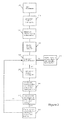
- Figure 2 is a flow diagram illustrating operation of the system 100 equipped for display of automatically-updated bearing and other navigational indicators (e.g., altitude).
- the system may provide for such auto-updating in all or selected phases of flight, e.g., by default and/or by pilot action (e.g., via input device 140). In the illustrated embodiment, however, it provides for such auto-updating only in connection with take-off procedures. It is from that perspective that the discussion below proceeds.
- the processing unit 110 receives a destination location input from the pilot (or other operator), e.g., via input device 140.
- the destination may be a waypoint (e.g., "LWM VOR), an airport/runway (e.g., "DTW ILS RWY 22L”) or other destination.
- the pilot or other operator may enter this information at any point in time, for purposes of the discussion that follows, it is assumed that the pilot will enter the information prior to taxiing down the runway for take-off.
- the processing unit 110 obtains a current location of the aircraft, as well as a bearing and any other parameters consistent with current flight navigation practice (e.g., altitude, attitude, etc.).
- the processing unit 110 uses the sensors, receivers and other apparatus 130 to obtain such information, although in other embodiments the processing unit 110 may obtain the information by other means (e.g., via manual input by the pilot, etc.).
- the processing unit 110 determines a relative bearing to the inputted destination, e.g., using any of many standard methodologies currently practiced in the area of flight navigation systems. For example, the processing unit 110 may compare the current location and bearing of the aircraft to the inputted destination and generate a corrected relative bearing that the aircraft may follow in order to safely reach the destination, e.g., as flight conditions, geography, air traffic, air space restrictions, the craft's performance capabilities or other conditions permit and/or dictate. Although in the illustrated embodiment, only bearing corrections or adjustments are determined in this step, in further embodiments, other navigational parameters may be determined, such as altitude corrections, speed corrections, etc.
- the processing unit 110 drives the display 120 to show indicators of the bearing (and other) corrections determined in step 220.
- These may be graphical (e.g., arrows, lines, etc.), alphanumeric (e.g., digits), or otherwise, in the conventional manner of bearing indicator displays. These may be overlaid on a 2D- or 3D- representation (generated as discussed above) of geography and/or airspace in the vicinity of the aircraft.
- a three-dimensional representation 300 of airspace and terrain includes depictions of a runway 310 and a mountain range 350, although in other embodiments other terrain or objects may be represented (e.g., lakes, oceans, aircraft, etc.).
- the illustrated display additionally includes graphical and digital representations of navigational information, including bearing and altitude indicators 320 directing the pilot to a pre-programmed waypoint or other destination (here, named "LWM VOR), as well as height and altitude displays 330.
- LWM VOR pre-programmed waypoint or other destination
- height and altitude displays 330 Although depicted here in black-and-white (or grayscale), it will be appreciated that in preferred embodiments such displays and representations may be in color.
- the aircraft in which system 100 is disposed is identified by aircraft icon 20 1.
- the aforementioned three-dimensional representation is generated from a designated perspective - here, that of a viewer on the aircraft and, more particularly, a viewer in the cockpit.
- Other embodiments may use other designated perspectives, e.g., from different vantage points on the aircraft, the ground or otherwise.
- the three-dimensional representation 300 of the airspace in the vicinity of the aircraft is a synthetic 3D image of that airspace as it would appear, e.g., under actual or ideal weather conditions, or otherwise, from the designated perspective; hence, it may not show all airspace in the vicinity of the host aircraft but, rather, only that sector of airspace visible from that perspective.
- these representations can be stylized (e.g., to highlight features of interest), wireframe or otherwise.
- step 240 the processing unit 110 determines whether the aircraft is taking off, e.g., taxiing on the runway, navigating toward a first waypoint, or executing some other maneuver commonly connected with take-off. In the illustrated embodiment, this is referred to as "take-off mode," although in other embodiments it may include other phases of flight as well or in addition, e.g., landing.
- normal mode If the craft is not in take-off mode, it is assumed to be in some other phase of flight (e.g., flying at altitude from the first waypoint to the final destination), referred to here as "normal mode.” In normal mode, as reflected in step 245, the processing unit 110 maintains the bearing indicator display that is currently displayed until a new destination is entered by the pilot (i.e., the indicators are static).
- the processing unit 110 obtains its current location, as well its bearing, altitude, etc. (as discussed above) from the sensors 130, also, as discussed above; see step 250.
- step 260 wherein the processing unit 110 re-calculates a relative bearing (and other navigational parameters, e.g., altitude correction) to the destination, e.g., in the same manner as discussed above in step 220.
- a relative bearing and other navigational parameters, e.g., altitude correction
- the processing unit 110 compares the re-calculated information with that currently displayed, per steps 230, 280. In the illustrated embodiment, if the differences are substantial - e.g., the re-calculated bearing differs from the displayed bearing by more than a selected variance (e.g., 30°, in some embodiments, 20° in other embodiments, 10° in still further embodiments, and so forth) - the processing unit 110 drives the display 120 to generate updated representations of the bearing and other navigational indicators; see, steps 270 and 280. This obviates the pilot having to re-program a destination into the unit in order to update the displays.
- a selected variance e.g. 30°, in some embodiments, 20° in other embodiments, 10° in still further embodiments, and so forth
- Figure 3B This is illustrated, by way of non-limiting example, in Figure 3B .
- a three-dimensional display 301 of the airspace and terrain are represented, e.g., as discussed above in reference to Figure 3A .
- Figure 3B additionally includes bearing and altitude indicators 325, also as discussed above in reference to Figure 3A , although here, by way of example, the indicators 325 display different bearing and altitude information (36" and 8500', respectively).
- the processing unit 110 maintains the currently displayed bearing indicators 320. Regardless, following steps 250 - 280, the processor loops back to step 240.
- Figure 4 is a flow diagram illustrating operation of the system 100 equipped for selective display of flexible and fixed HITS flight pathways.
- the system displays fixed HITS pathways when the aircraft is in the so-called normal mode (as defined above), e.g., when the craft has completed take-off maneuvers and is flying at altitude from a first waypoint to the final destination and during landing procedures.
- the illustrated system displays flexible HITS pathways when the aircraft is in take-off mode (also, as defined above), e.g., when the craft is navigating toward a first waypoint, or executing some other maneuver commonly connected with take-off.
- the illustrated system will display a flexible HITS pathway, but, automatically switch to display of fixed HITS pathways, e.g., (i) when the craft completes its take-off procedure, for example, by reaching the first waypoint (or other destination) programmed into the system 100, (ii) when the craft comes within a predetermined variance of distance of and/or bearing to that waypoint (or other destination), and/or (iii) when flight conditions, geography, air traffic, air space restrictions, the craft's performance capabilities or other conditions dictate (for safety or other reasons) that the flight management system switch from the first to the second mode (i.e., from flexible to a fixed HITS display).
- the processing unit 110 receives a destination location input from the pilot (or other operator), e.g., via input device 140.
- the destination may be a waypoint (e.g., "LWM VOR"), an airport/runway (e.g., "DTW ILS RWY 22L”) or other destination.
- the pilot or other operator may enter this information at any point in time, for purposes of the discussion that follows, it is assumed that the pilot will enter the information prior to taxiing down the runway for take-off or at a subsequent time, when the craft is in flight.
- step 4 10 the processing unit 110 determines whether the craft is in normal or take-off mode. If in normal mode (e.g., en route from a waypoint to a final destination), as indicated in step 41 5, the processing unit 110 drives the display 120 to generate a representation of a "fixed" HITS pathway to the destination. This is depicted, by way of example, in Figure 5D , showing fixed HITS pathway 540 originating at a waypoint and terminating at a destination 542. That waypoint is assumed to be behind the craft for purposes of illustration and, hence, is not shown in the drawing.
- Logic executed by the processor to generate that pathway 540 may be of the type known in the art for generating fixed HITS pathways, e.g., as a function of official airways or approach paths defined by the FAA and/or other agencies, the craft's operational capabilities, and so forth.
- a pathway is fixed and does not move relative to the aircraft, but rather maintains the same position irrespective of the aircraft's current location.
- the portion of the pathway 540 ahead of the craft would remain visible; however, the craft icon 201 would no longer be centered at the opening of the displayed pathway 540.
- the pathway 540 is overlaid on a 2D- or 3D- representation 503 (generated as discussed above) of geography and/or airspace in the vicinity of the aircraft, e.g., as shown in Figure 5D .
- the processing unit 110 determines whether to display the HITS pathway in fixed or flexible mode. To this end, in step 420, the processor obtains a current location of the aircraft, as well as the bearing, altitude, etc. (e.g., in the manner discussed above). The processing unit 110 uses the aircraft's location and operational capabilities (e.g., as maintained in store 114), etc., to determine whether the aircraft has deviated substantially beyond a previously determined flight path to the destination (i.e., the aircraft is too far off-course). This may be based solely on distance, as where the processing unit determines a vehicle is off-course if it is 2500', 5000' or so forth from a previously determined flight path.
- it may also be based on flight conditions, geography, air traffic, air space restrictions, the craft's performance capabilities and so forth. Thus, for example, if the craft is less than 2500' from the original flight path by direct travel, but by more than 5000' for a route circumventing intervening restricted airspace, air traffic or other obstacles, then the latter figure is used in determining whether the craft has deviated substantially off course.
- the processing unit 110 will drive the display 120 to generate a representation of a fixed HITS pathway to the destination (again, as above, using conventional logic known in the art for generating such pathways), e.g., overlaid on a 2D- or 3D- representation (generated as discussed above) of geography and/or airspace in the vicinity of the aircraft.
- a representation of a fixed HITS pathway to the destination (again, as above, using conventional logic known in the art for generating such pathways), e.g., overlaid on a 2D- or 3D- representation (generated as discussed above) of geography and/or airspace in the vicinity of the aircraft.
- determination of that fixed pathway may be made in the conventional manner known in the art, e.g., as a function of official airways defined by the FAA and/or other agencies, the craft's operational capabilities, and so forth.
- the processor 110 further determines whether the aircraft is within range of any obstacles (e.g., mountains, aircraft, restricted airspace, etc.).
- the selected range may a pre-defined minimum distance the aircraft is allowed to maintain from such obstacles (e.g., 0.5 miles, in some embodiments, 1 mile in other embodiments, 5 miles in still further embodiments, and so forth), though, in some embodiments, that minimum may take into account operational capabilities of the craft (e.g., as maintained in store 114).
- the processing unit 110 drives the display 120 to generate a warning (e.g., a flashing red light on the display 120, etc.), and a fixed HITS pathway (as above, using conventional logic known in the art for generating such pathways) on a 2D- or 3Drepresentation (generated as discussed above) of geography and/or airspace in the vicinity of the aircraft.
- a warning e.g., a flashing red light on the display 120, etc.
- a fixed HITS pathway as above, using conventional logic known in the art for generating such pathways
- 2D- or 3Drepresentation generated as discussed above
- the processing unit 110 drives the display to generate a flexible HITS pathway representing a flight path from the aircraft's current location to the destination. Examples of this are provided by pathways 510 of Figure 5A and 520 of Figure 5B , both originating at the craft and terminating at a destination (not shown). Such pathways (and, particularly, their origins) move with the craft and, hence, the craft icon 201 remains centered at the opening of the displayed pathways (e.g., so long as the system 100 continues to display a flexible pathway).
- Logic executed by the processor to generate that pathway may be adapted from that known in the art for generating fixed HITS pathways, albeit using the craft's current location as a starting point of the pathway.
- the depiction of the flexible HITS pathway is overlaid on a 2D- or 3D- representation (generated as discussed above) of geography and/or airspace in the vicinity of the aircraft.
- the flexible HITS flight pathway 510, 520 automatically updates depending on the location, bearing, etc., of the aircraft. This can be effected by the return logic loop shown between steps 440 and 410 in the drawing or otherwise.
- Figures 5A - 5B depict three-dimensional (3D) graphical displays 500, 501 of the type generated by system 100, including depictions of flexible highway-in-the-sky (HITS) flight paths 510, 520, as discussed above. These additionally include depictions of runway 310, mountains 350, bearing and navigational indicators 531, and other navigational information 330, as well as the aircraft icon 201 itself.
- HITS flexible highway-in-the-sky
- Figures 5C - 5D depict three-dimensional (3D) graphical displays 502, 503 of the type generated by system 100, including depictions of fixed highway-in-the-sky (HITS) flight paths 530, 540, again, as discussed above. These, too, include depictions of mountains 350, bearing and navigational indicators 531, a destination 542, and other navigational information 330. as well as the aircraft icon 201 itself.
- HITS highway-in-the-sky
- the system 100 can display a flight path that is flexible along one (or more) portion(s) and fixed along one (or more) other portion(s).
- An example of this is shown in Figure 6 , depicting a three-dimensional (3D) graphical display 600 of the type generated by system 100, including a depiction of a highway-in-the-sky (HITS) flight path 610 that is flexible along a first portion 611 and fixed along a second portion 612.
- HITS highway-in-the-sky
- this includes depictions of mountains 350, bearing and navigational indicators 531, a destination 542, and other navigational information 330, as well as the aircraft 201 1 icon itself.
- dashed lines 511, 521, 522, and 61 3 are provided to more clearly illustrate the respective (three-dimensional) HITS pathways to the reader. Such lines may or may not be displayed by systems according to the invention, which may alternatively use shading, coloration or other graphical techniques to depict such pathways.
- the aforementioned three-dimensional representations are generated from a designated perspective - here, that of a viewer on the aircraft and, more particularly, a viewer in the cockpit.
- Other embodiments may use other designated perspectives, e.g., from different vantage points on the aircraft.
- the three-dimensional representations of the airspace in the vicinity of the aircraft is a synthetic 3D image of that airspace as it would appear, e.g., under actual or ideal weather conditions, or otherwise, from the designated perspective; hence, it may not show all airspace in the vicinity of the host aircraft but, rather, only that sector of airspace visible from that perspective).
- these representations can be stylized (e.g., to highlight features of interest), wireframe or otherwise.
Landscapes
- Engineering & Computer Science (AREA)
- Radar, Positioning & Navigation (AREA)
- Remote Sensing (AREA)
- Aviation & Aerospace Engineering (AREA)
- Physics & Mathematics (AREA)
- General Physics & Mathematics (AREA)
- Traffic Control Systems (AREA)
- Navigation (AREA)
Applications Claiming Priority (1)
| Application Number | Priority Date | Filing Date | Title |
|---|---|---|---|
| US11/963,763 US7869943B1 (en) | 2007-12-21 | 2007-12-21 | Flight management systems and methods for use with an aerial vehicle |
Publications (2)
| Publication Number | Publication Date |
|---|---|
| EP2072956A2 true EP2072956A2 (de) | 2009-06-24 |
| EP2072956A3 EP2072956A3 (de) | 2014-03-26 |
Family
ID=40386388
Family Applications (1)
| Application Number | Title | Priority Date | Filing Date |
|---|---|---|---|
| EP08171719.1A Withdrawn EP2072956A3 (de) | 2007-12-21 | 2008-12-15 | Flugmanagementsysteme und -verfahren zur Verwendung mit einem Luftfahrzeug |
Country Status (2)
| Country | Link |
|---|---|
| US (1) | US7869943B1 (de) |
| EP (1) | EP2072956A3 (de) |
Cited By (4)
| Publication number | Priority date | Publication date | Assignee | Title |
|---|---|---|---|---|
| EP2369297A1 (de) * | 2010-03-23 | 2011-09-28 | Thales | Vorrichtung zur Flughilfe für Luftfahrzeug |
| RU2773981C1 (ru) * | 2022-01-11 | 2022-06-14 | Федеральное государственное автономное образовательное учреждение высшего образования "Северный (Арктический) федеральный университет имени М. В. Ломоносова" | Пилотажно-навигационная система транспортного летательного аппарата |
| US20220341754A1 (en) * | 2019-06-04 | 2022-10-27 | Hung-Hsin Lin | Aircraft flight attitude display device |
| EP4459595A4 (de) * | 2021-12-27 | 2026-04-29 | Nabla Mobility Inc | Informationsverarbeitungsvorrichtung, informationsverarbeitungsverfahren und programm |
Families Citing this family (16)
| Publication number | Priority date | Publication date | Assignee | Title |
|---|---|---|---|---|
| US20100023264A1 (en) * | 2008-07-23 | 2010-01-28 | Honeywell International Inc. | Aircraft display systems and methods with obstacle warning envelopes |
| US8965601B1 (en) * | 2008-09-23 | 2015-02-24 | Rockwell Collins, Inc. | System, module, and method for presenting a flight director-dependent hits pathway on an aircraft display unit |
| US8849477B2 (en) * | 2008-10-14 | 2014-09-30 | Honeywell International Inc. | Avionics display system and method for generating three dimensional display including error-compensated airspace |
| US8362925B2 (en) * | 2009-05-05 | 2013-01-29 | Honeywell International Inc. | Avionics display system and method for generating flight information pertaining to neighboring aircraft |
| US8589071B2 (en) * | 2011-08-15 | 2013-11-19 | Honeywell International Inc. | Aircraft vision system including a runway position indicator |
| US8581748B1 (en) * | 2011-09-20 | 2013-11-12 | Rockwell Collins, Inc. | System, device, and method for generating an ILS-based highway-in-the-sky |
| US8698654B2 (en) * | 2011-12-28 | 2014-04-15 | Honeywell International Inc. | System and method for selecting images to be displayed |
| US8566027B2 (en) | 2012-03-14 | 2013-10-22 | Lockheed Martin Corporation | Route re-planning using enemy force lethality projection |
| US9874456B2 (en) * | 2014-11-28 | 2018-01-23 | Here Global B.V. | Method, apparatus and computer program product for providing a destination preview |
| FR3044401B1 (fr) * | 2015-11-27 | 2017-12-01 | Thales Sa | Procede de calcul et de representation des ecarts a la trajectoire d'un aeronef en vol |
| SG11201810080UA (en) * | 2016-07-26 | 2019-02-27 | Milian International Solutions Ltd | System and method for 3d flight path display |
| EP4035943B1 (de) | 2016-11-01 | 2023-08-30 | Panasonic Intellectual Property Corporation of America | Anzeigeverfahren und anzeigevorrichtung |
| US10582456B2 (en) * | 2017-06-07 | 2020-03-03 | Ethertronics, Inc. | Power control method for systems with altitude changing objects |
| US10446041B1 (en) * | 2018-08-23 | 2019-10-15 | Kitty Hawk Corporation | User interfaces for mutually exclusive three dimensional flying spaces |
| US10438495B1 (en) | 2018-08-23 | 2019-10-08 | Kitty Hawk Corporation | Mutually exclusive three dimensional flying spaces |
| US11789441B2 (en) | 2021-09-15 | 2023-10-17 | Beta Air, Llc | System and method for defining boundaries of a simulation of an electric aircraft |
Family Cites Families (34)
| Publication number | Priority date | Publication date | Assignee | Title |
|---|---|---|---|---|
| US2784307A (en) | 1952-08-25 | 1957-03-05 | Flite Tronics Inc | Marker beacon receiver |
| US3711826A (en) | 1969-05-23 | 1973-01-16 | Farrand Optical Co Inc | Instrument landing apparatus for aircraft |
| US3605083A (en) | 1969-10-08 | 1971-09-14 | Sperry Rand Corp | Attitude and flight director display apparatus utilizing a cathode-ray tube having a polar raster |
| US3643213A (en) | 1969-11-24 | 1972-02-15 | Bendix Corp | Method and means for providing a synthetic real world runway display |
| US3786505A (en) | 1970-03-04 | 1974-01-15 | J Rennie | Self-contained navigation system |
| US3843554A (en) | 1970-09-24 | 1974-10-22 | Du Pont | Catalyst compositions of scheelite crystal structure containing vanadium,bismuth and cation vacancies |
| US3784969A (en) | 1971-12-29 | 1974-01-08 | V Wilckens | Aircraft landing display apparatus |
| US3789356A (en) | 1972-07-10 | 1974-01-29 | Mc Donnell Douglas Corp | Monitor display means |
| US4057782A (en) | 1976-04-05 | 1977-11-08 | Sundstrand Data Control, Inc. | Low altitude head up display for aircraft |
| US4368517A (en) | 1978-03-16 | 1983-01-11 | Bunker Ramo Corporation | Aircraft landing display system |
| ZA801538B (en) | 1979-03-19 | 1981-04-29 | United Kingdom Government | Method and apparatus for estimating slant visibility in fog |
| US4316252A (en) | 1979-08-10 | 1982-02-16 | The Boeing Company | Apparatus for determining the position of an aircraft with respect to the runway |
| FR2487505A1 (fr) | 1980-07-23 | 1982-01-29 | Dassault Avions | Dispositif d'assistance au pilotage d'un vehicule aerien |
| US4660157A (en) | 1981-10-02 | 1987-04-21 | Harris Corporation | Real time video perspective digital map display method |
| US4825374A (en) | 1985-12-20 | 1989-04-25 | The Boeing Company | Aircraft descent guide system and method for creating descent guidance information |
| US5047942A (en) | 1987-08-06 | 1991-09-10 | The United States Of America As Represented By The Administrator Of The National Aeronautics And Space Administration | Airplane takeoff and landing performance monitoring system |
| DE3904344A1 (de) | 1989-02-14 | 1990-08-16 | Bosch Gmbh Robert | Verfahren zum lesen von navigationsdaten einer compact-disc |
| US4999780A (en) | 1989-03-03 | 1991-03-12 | The Boeing Company | Automatic reconfiguration of electronic landing display |
| EP0399670A3 (de) | 1989-05-25 | 1993-04-07 | British Aerospace Public Limited Company | Computererzeugte Bildanzeigesysteme auf Flugzeugen |
| NL8901695A (nl) | 1989-07-04 | 1991-02-01 | Koninkl Philips Electronics Nv | Werkwijze voor het weergeven van navigatiegegevens voor een voertuig in een omgevingsbeeld van het voertuig, navigatiesysteem voor het uitvoeren van de werkwijze, alsmede voertuig voorzien van een navigatiesysteem. |
| FR2689668B1 (fr) | 1992-04-07 | 1994-05-20 | Dassault Electronique | Procede et dispositif d'anti-collisions terrain pour aeronef. |
| US5343395A (en) | 1992-08-26 | 1994-08-30 | Watts Alan B | Aircraft landing guidance system and method |
| US5355442A (en) | 1992-12-16 | 1994-10-11 | Loral Aerospace Corp. | Terrain visualization by ray tracing a conical height field transformation |
| US5566073A (en) | 1994-07-11 | 1996-10-15 | Margolin; Jed | Pilot aid using a synthetic environment |
| US5904724A (en) | 1996-01-19 | 1999-05-18 | Margolin; Jed | Method and apparatus for remotely piloting an aircraft |
| WO2000065423A2 (en) | 1999-04-01 | 2000-11-02 | Price Ricardo A | Electronic flight instrument displays |
| US6480789B2 (en) | 2000-12-04 | 2002-11-12 | American Gnc Corporation | Positioning and proximity warning method and system thereof for vehicle |
| US6804585B2 (en) | 2001-06-19 | 2004-10-12 | John Jay Humbard | Flight management system and method for providing navigational reference to emergency landing locations |
| US20030132860A1 (en) * | 2001-09-21 | 2003-07-17 | Honeywell International, Inc. | Interface for visual cueing and control for tactical flightpath management |
| US7010398B2 (en) * | 2001-10-11 | 2006-03-07 | The Boeing Company | Control system providing perspective flight guidance |
| FR2848662B1 (fr) | 2002-12-17 | 2005-03-04 | Thales Sa | Dispositif d'affichage pour equipement anticollision terrain embarque a bord d'aeronef |
| WO2005057133A1 (en) * | 2003-11-25 | 2005-06-23 | Honeywell International, Inc. | Perspective vertical situation display system and method |
| US7352292B2 (en) | 2006-01-20 | 2008-04-01 | Keith Alter | Real-time, three-dimensional synthetic vision display of sensor-validated terrain data |
| US7728758B2 (en) * | 2007-03-07 | 2010-06-01 | Honeywell International Inc. | Method and system for maintaining spatio-temporal data |
-
2007
- 2007-12-21 US US11/963,763 patent/US7869943B1/en not_active Expired - Fee Related
-
2008
- 2008-12-15 EP EP08171719.1A patent/EP2072956A3/de not_active Withdrawn
Cited By (7)
| Publication number | Priority date | Publication date | Assignee | Title |
|---|---|---|---|---|
| EP2369297A1 (de) * | 2010-03-23 | 2011-09-28 | Thales | Vorrichtung zur Flughilfe für Luftfahrzeug |
| FR2958031A1 (fr) * | 2010-03-23 | 2011-09-30 | Thales Sa | Dispositif d'aide au vol pour un aeronef |
| US8525699B2 (en) | 2010-03-23 | 2013-09-03 | Thales | Device for aiding flight for an aircraft |
| US20220341754A1 (en) * | 2019-06-04 | 2022-10-27 | Hung-Hsin Lin | Aircraft flight attitude display device |
| US12276524B2 (en) * | 2019-06-04 | 2025-04-15 | Hung-Hsin Lin | Aircraft flight attitude display device |
| EP4459595A4 (de) * | 2021-12-27 | 2026-04-29 | Nabla Mobility Inc | Informationsverarbeitungsvorrichtung, informationsverarbeitungsverfahren und programm |
| RU2773981C1 (ru) * | 2022-01-11 | 2022-06-14 | Федеральное государственное автономное образовательное учреждение высшего образования "Северный (Арктический) федеральный университет имени М. В. Ломоносова" | Пилотажно-навигационная система транспортного летательного аппарата |
Also Published As
| Publication number | Publication date |
|---|---|
| US7869943B1 (en) | 2011-01-11 |
| EP2072956A3 (de) | 2014-03-26 |
Similar Documents
| Publication | Publication Date | Title |
|---|---|---|
| US7869943B1 (en) | Flight management systems and methods for use with an aerial vehicle | |
| EP2533015B1 (de) | Verfahren und Systeme zur Anzeige von Prozedurinformation auf einem Flugzeugbildschirm | |
| US7783393B2 (en) | Enhanced vertical situation display | |
| US7010398B2 (en) | Control system providing perspective flight guidance | |
| CN104807474B (zh) | 在旋翼飞行器中显示飞行路径信息的系统和方法 | |
| EP2560152B1 (de) | Flugzeugsichtsystem mit Landebahnpositionsanzeige | |
| EP1896797B1 (de) | Primäre fluganzeige mit perspektivenansicht mit geländeverfolgungslinien | |
| EP2808856B1 (de) | System und Verfahren zur Anzeige eines Landebahn-Positionsanzeigers | |
| US8032267B1 (en) | Aviation navigational and flight management systems and methods with emergency landing guidance and radar vectoring | |
| US7917289B2 (en) | Perspective view primary flight display system and method with range lines | |
| US12033250B2 (en) | Capability envelope display methods and systems | |
| EP3961603B1 (de) | Verfahren und systeme zur anzeige der horizontalen ausweichführung | |
| EP2557552A1 (de) | Flugzeugsichtsystem mit Redundanz für Annäherungen in geringer Höhe | |
| EP2355070A2 (de) | Verfahren und Systeme zur Eingabe von Flugzeugrangieranweisungen | |
| EP2166311B1 (de) | Vorrichtung und Verfahren zur Einstellung eines Wegpunkts | |
| EP1462767B1 (de) | Flugzeugleitsystem und -verfahren zur Bereitstellung von perspektivischer Flugführung | |
| US8185301B1 (en) | Aircraft traffic awareness system and methods | |
| CN112419788A (zh) | 无人机检测系统和相关呈现方法 | |
| US11056011B2 (en) | Method and electronic device of management of the display of an aircraft flying profile, associated computer program and electronic system | |
| US7499794B1 (en) | System and method for improved mapping of a location | |
| EP3657131A1 (de) | Verfahren und systeme zur darstellung von wegpunktlisten |
Legal Events
| Date | Code | Title | Description |
|---|---|---|---|
| PUAI | Public reference made under article 153(3) epc to a published international application that has entered the european phase |
Free format text: ORIGINAL CODE: 0009012 |
|
| 17P | Request for examination filed |
Effective date: 20081215 |
|
| AK | Designated contracting states |
Kind code of ref document: A2 Designated state(s): AT BE BG CH CY CZ DE DK EE ES FI FR GB GR HR HU IE IS IT LI LT LU LV MC MT NL NO PL PT RO SE SI SK TR |
|
| AX | Request for extension of the european patent |
Extension state: AL BA MK RS |
|
| RIC1 | Information provided on ipc code assigned before grant |
Ipc: G01C 23/00 20060101AFI20131022BHEP |
|
| PUAL | Search report despatched |
Free format text: ORIGINAL CODE: 0009013 |
|
| AK | Designated contracting states |
Kind code of ref document: A3 Designated state(s): AT BE BG CH CY CZ DE DK EE ES FI FR GB GR HR HU IE IS IT LI LT LU LV MC MT NL NO PL PT RO SE SI SK TR |
|
| AX | Request for extension of the european patent |
Extension state: AL BA MK RS |
|
| RIC1 | Information provided on ipc code assigned before grant |
Ipc: G01C 23/00 20060101AFI20140214BHEP |
|
| AKX | Designation fees paid |
Designated state(s): BE DE FR GB |
|
| RAP1 | Party data changed (applicant data changed or rights of an application transferred) |
Owner name: HONEYWELL INTERNATIONAL INC. |
|
| STAA | Information on the status of an ep patent application or granted ep patent |
Free format text: STATUS: THE APPLICATION HAS BEEN WITHDRAWN |
|
| 18W | Application withdrawn |
Effective date: 20180504 |