EP2072977A1 - Système de capteur, en particulier pour un véhicule automobile - Google Patents
Système de capteur, en particulier pour un véhicule automobile Download PDFInfo
- Publication number
- EP2072977A1 EP2072977A1 EP08105651A EP08105651A EP2072977A1 EP 2072977 A1 EP2072977 A1 EP 2072977A1 EP 08105651 A EP08105651 A EP 08105651A EP 08105651 A EP08105651 A EP 08105651A EP 2072977 A1 EP2072977 A1 EP 2072977A1
- Authority
- EP
- European Patent Office
- Prior art keywords
- sensor device
- light
- diffuser
- motor vehicle
- sensor
- Prior art date
- Legal status (The legal status is an assumption and is not a legal conclusion. Google has not performed a legal analysis and makes no representation as to the accuracy of the status listed.)
- Withdrawn
Links
- 230000005855 radiation Effects 0.000 claims abstract description 11
- 238000004378 air conditioning Methods 0.000 description 3
- 238000001514 detection method Methods 0.000 description 3
- 238000005259 measurement Methods 0.000 description 3
- 230000001419 dependent effect Effects 0.000 description 2
- 238000010586 diagram Methods 0.000 description 2
- 238000009423 ventilation Methods 0.000 description 2
- 230000037237 body shape Effects 0.000 description 1
- 238000010276 construction Methods 0.000 description 1
- 230000000694 effects Effects 0.000 description 1
- 238000011156 evaluation Methods 0.000 description 1
- 238000000034 method Methods 0.000 description 1
- 230000003287 optical effect Effects 0.000 description 1
- 230000001105 regulatory effect Effects 0.000 description 1
- 230000035945 sensitivity Effects 0.000 description 1
- 238000001228 spectrum Methods 0.000 description 1
Images
Classifications
-
- G—PHYSICS
- G01—MEASURING; TESTING
- G01J—MEASUREMENT OF INTENSITY, VELOCITY, SPECTRAL CONTENT, POLARISATION, PHASE OR PULSE CHARACTERISTICS OF INFRARED, VISIBLE OR ULTRAVIOLET LIGHT; COLORIMETRY; RADIATION PYROMETRY
- G01J1/00—Photometry, e.g. photographic exposure meter
- G01J1/02—Details
- G01J1/04—Optical or mechanical part supplementary adjustable parts
- G01J1/0407—Optical elements not provided otherwise, e.g. manifolds, windows, holograms, gratings
- G01J1/0411—Optical elements not provided otherwise, e.g. manifolds, windows, holograms, gratings using focussing or collimating elements, i.e. lenses or mirrors; Aberration correction
-
- G—PHYSICS
- G01—MEASURING; TESTING
- G01J—MEASUREMENT OF INTENSITY, VELOCITY, SPECTRAL CONTENT, POLARISATION, PHASE OR PULSE CHARACTERISTICS OF INFRARED, VISIBLE OR ULTRAVIOLET LIGHT; COLORIMETRY; RADIATION PYROMETRY
- G01J1/00—Photometry, e.g. photographic exposure meter
- G01J1/02—Details
- G01J1/04—Optical or mechanical part supplementary adjustable parts
- G01J1/0407—Optical elements not provided otherwise, e.g. manifolds, windows, holograms, gratings
- G01J1/0422—Optical elements not provided otherwise, e.g. manifolds, windows, holograms, gratings using light concentrators, collectors or condensers
-
- G—PHYSICS
- G01—MEASURING; TESTING
- G01J—MEASUREMENT OF INTENSITY, VELOCITY, SPECTRAL CONTENT, POLARISATION, PHASE OR PULSE CHARACTERISTICS OF INFRARED, VISIBLE OR ULTRAVIOLET LIGHT; COLORIMETRY; RADIATION PYROMETRY
- G01J1/00—Photometry, e.g. photographic exposure meter
- G01J1/02—Details
- G01J1/04—Optical or mechanical part supplementary adjustable parts
- G01J1/0407—Optical elements not provided otherwise, e.g. manifolds, windows, holograms, gratings
- G01J1/0451—Optical elements not provided otherwise, e.g. manifolds, windows, holograms, gratings using means for illuminating a slit efficiently, e.g. entrance slit of a photometer or entrance face of fiber
-
- G—PHYSICS
- G01—MEASURING; TESTING
- G01J—MEASUREMENT OF INTENSITY, VELOCITY, SPECTRAL CONTENT, POLARISATION, PHASE OR PULSE CHARACTERISTICS OF INFRARED, VISIBLE OR ULTRAVIOLET LIGHT; COLORIMETRY; RADIATION PYROMETRY
- G01J1/00—Photometry, e.g. photographic exposure meter
- G01J1/42—Photometry, e.g. photographic exposure meter using electric radiation detectors
- G01J1/4204—Photometry, e.g. photographic exposure meter using electric radiation detectors with determination of ambient light
-
- G—PHYSICS
- G01—MEASURING; TESTING
- G01J—MEASUREMENT OF INTENSITY, VELOCITY, SPECTRAL CONTENT, POLARISATION, PHASE OR PULSE CHARACTERISTICS OF INFRARED, VISIBLE OR ULTRAVIOLET LIGHT; COLORIMETRY; RADIATION PYROMETRY
- G01J1/00—Photometry, e.g. photographic exposure meter
- G01J1/02—Details
- G01J1/0271—Housings; Attachments or accessories for photometers
-
- G—PHYSICS
- G01—MEASURING; TESTING
- G01J—MEASUREMENT OF INTENSITY, VELOCITY, SPECTRAL CONTENT, POLARISATION, PHASE OR PULSE CHARACTERISTICS OF INFRARED, VISIBLE OR ULTRAVIOLET LIGHT; COLORIMETRY; RADIATION PYROMETRY
- G01J1/00—Photometry, e.g. photographic exposure meter
- G01J1/42—Photometry, e.g. photographic exposure meter using electric radiation detectors
- G01J2001/4266—Photometry, e.g. photographic exposure meter using electric radiation detectors for measuring solar light
Definitions
- a generic sensor device for the control of a temperature-influencing device of a motor vehicle such as an air conditioner or a ventilation
- a temperature-influencing device of a motor vehicle such as an air conditioner or a ventilation
- a light guide lens optics
- three receivers is detected by the light or solar radiation.
- the air conditioning system or the ventilation of the motor vehicle is regulated, for example.
- the focal point of the incident sunlight generated by the lens optics migrates depending on the sun angle on the photosensitive surface of the receiver. At constant light intensity, differently sized areas of the receiver are applied as a function of the incident sun angle, thereby producing different large signals at the receiver.
- the size of the focus or light spot should correspond approximately to the size of the photosensitive surface of the receiver.
- the size of the light-sensitive area is smaller than that of the light spot (focal point)
- the characteristic of the light signal changes depending on the location, such that ambiguities, ie angle values, to which a plurality of light signal values can be assigned, increasingly occur. This means that no definite angle can be calculated from the measured value supplied by the sensor. The effect increases when using receivers or detectors with small photosensitive surfaces.
- a photodetector system with influenceable position-dependent sensitivity is shown and described, which has inter alia a light diffuser for scattering the light striking the photodetector.
- this arrangement does not have a lens system for focusing the sunlight and, depending on the angle of the sun's rays, the distance that the light has to travel through the diffuser to reach the detector also changes. Due to the hemispherical structure of the diffuser considerable space is further claimed, for example, a space-saving recording in a built-in front windshield rain sensor / sunlight sensor module difficult.
- the object of the invention is to avoid the above-mentioned disadvantages of such a sensor device.
- the diffuser element By using a diffuser element arranged between lens optic and receiver, it has been possible experimentally to prove that a more homogeneous course of the sun angle characteristic can be achieved.
- the characteristic areas are "smoothed" and the photosensitive surface increased.
- the latter has the advantage that receivers or light sensors can be used with smaller photosensitive surfaces. This in turn brings cost advantages, since the prices for such sensor devices are highly dependent on the size of the photosensitive chip area.
- the height (H) and the width (B) of the cuboid-shaped diffuser element are matched in an advantageous manner to the size of the receiver element of the sensor device. This ensures a replicable homogeneous measurement result, despite vehicle-related different sized sensor devices.
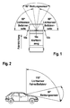
- the sun position sensor 10 In common motor vehicles sensor devices are used, via which by means of a receiver element, hereinafter referred to as the sun position sensor 10, the irradiation and the intensity of the heat radiation is determined by the sun on the vehicle interior. With the help of the measuring signals of the Sun position sensor 10, the control of the air conditioning system of the motor vehicle is influenced, such that the more sun-exposed side of the motor vehicle is more cooled by the air conditioning (mono-zone or bizonal air conditioners). In the present embodiment -as in FIG.
- the sensor used is generally a light-sensitive diode (LDR), a photosensitive transistor or a comparable photosensitive component with a corresponding evaluation circuit.
- LDR light-sensitive diode
- the angle-specific alignment of the detection areas of the three sensors 10a, 10b and 10c is effected by a lens arrangement 12 specially designed for this purpose, which will be described in more detail later.
- the first and second sensors 10a, 10b each detect a range of approximately 80 ° on the driver or passenger side, while the third sensor 10c as a so-called Riehtungssensor the light radiation in one area detected by about 60 ° directly forward.
- the sensors 10a, 10b on the driver and front passenger side are each aligned at approximately 45 ° upwards and cover an opening angle of about 110 °; the direction sensor 10c is also usually oriented 45 ° upwards and has an opening angle of about 30 ° (see FIG. 2 ).
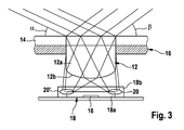
- the following is based on FIG. 3 with the help of a section through a windshield of a motor vehicle, the structure of the sensors 10a, 10b, 10c explained in more detail. Since the construction of all three sensors is essentially the same, is in FIG. 3 only one sensor 10 has been shown.
- the lens assembly 12 is attached to the inside of the windscreen 14 of the motor vehicle.
- the sensor 10 in this case has a light-sensitive chip 16, which is formed, for example, as a CCD element or as a simple photodiode.
- the photosensitive chip 16 is surrounded by a light diffuser element, hereinafter referred to as a diffuser 18, whose operation will be explained below.
- a diffuser 18 a light diffuser element
- FIG. 3 For illustration of the principle of operation, two diffuser elements 18a, 18b with different dimensions (height (H) and width (B)) are shown, wherein in the practical embodiment only one diffuser element 18 is used.
- the diffuser element 18 formed by the body shape as a cuboid encloses the chip 16 completely with its cover and the four side surfaces.
- the focal point 20 is also at least partially within the diffuser 18 and is thus detected by the photosensitive chip 16 as a measurement signal. Solar radiation within the angular range ⁇ - ⁇ on the windshield 14 impinges is then completely detected by the smaller sized diffuser 18a.
Landscapes
- Physics & Mathematics (AREA)
- General Physics & Mathematics (AREA)
- Spectroscopy & Molecular Physics (AREA)
- Life Sciences & Earth Sciences (AREA)
- Sustainable Development (AREA)
- Air-Conditioning For Vehicles (AREA)
- Photometry And Measurement Of Optical Pulse Characteristics (AREA)
Applications Claiming Priority (1)
| Application Number | Priority Date | Filing Date | Title |
|---|---|---|---|
| DE200710061746 DE102007061746A1 (de) | 2007-12-20 | 2007-12-20 | Sensoreinrichtung, insbesondere für ein Kraftfahrzeug |
Publications (1)
| Publication Number | Publication Date |
|---|---|
| EP2072977A1 true EP2072977A1 (fr) | 2009-06-24 |
Family
ID=40394039
Family Applications (1)
| Application Number | Title | Priority Date | Filing Date |
|---|---|---|---|
| EP08105651A Withdrawn EP2072977A1 (fr) | 2007-12-20 | 2008-10-24 | Système de capteur, en particulier pour un véhicule automobile |
Country Status (2)
| Country | Link |
|---|---|
| EP (1) | EP2072977A1 (fr) |
| DE (1) | DE102007061746A1 (fr) |
Cited By (1)
| Publication number | Priority date | Publication date | Assignee | Title |
|---|---|---|---|---|
| NL2016814B1 (en) * | 2016-05-23 | 2017-11-30 | Kipp & Zonen B V | Device for measurement of direct sunbeam irradiance |
Families Citing this family (1)
| Publication number | Priority date | Publication date | Assignee | Title |
|---|---|---|---|---|
| DE102010026561A1 (de) * | 2010-07-08 | 2012-01-12 | Hella Kgaa Hueck & Co. | Sensoreinheit zur Erfassung der Umgebungslichtverhältnisse |
Citations (6)
| Publication number | Priority date | Publication date | Assignee | Title |
|---|---|---|---|---|
| DE1166500B (de) * | 1959-08-01 | 1964-03-26 | Zeiss Ikon Ag | Photoelektrischer Belichtungsmesser mit Lichtstrahlenbegrenzer |
| DE68910025T2 (de) | 1988-07-15 | 1994-03-03 | Dennis J Hegyi | Photodetektorsystem mit beeinflussbarer positionsabhängiger Empfindlichkeit. |
| US20020047085A1 (en) * | 2000-10-24 | 2002-04-25 | Kazuyoshi Sumiya | Solar sensor |
| US20040130789A1 (en) * | 1999-01-25 | 2004-07-08 | Bechtel Jon H. | Sensor device having an integral lens |
| DE102004055060A1 (de) | 2004-10-30 | 2006-05-04 | Robert Bosch Gmbh | Sensoreinrichtung, insbesondere für ein Kraftfahrzeug |
| DE102005047061A1 (de) * | 2005-09-30 | 2007-04-05 | Osram Opto Semiconductors Gmbh | Strahlungsdetektor |
-
2007
- 2007-12-20 DE DE200710061746 patent/DE102007061746A1/de not_active Withdrawn
-
2008
- 2008-10-24 EP EP08105651A patent/EP2072977A1/fr not_active Withdrawn
Patent Citations (6)
| Publication number | Priority date | Publication date | Assignee | Title |
|---|---|---|---|---|
| DE1166500B (de) * | 1959-08-01 | 1964-03-26 | Zeiss Ikon Ag | Photoelektrischer Belichtungsmesser mit Lichtstrahlenbegrenzer |
| DE68910025T2 (de) | 1988-07-15 | 1994-03-03 | Dennis J Hegyi | Photodetektorsystem mit beeinflussbarer positionsabhängiger Empfindlichkeit. |
| US20040130789A1 (en) * | 1999-01-25 | 2004-07-08 | Bechtel Jon H. | Sensor device having an integral lens |
| US20020047085A1 (en) * | 2000-10-24 | 2002-04-25 | Kazuyoshi Sumiya | Solar sensor |
| DE102004055060A1 (de) | 2004-10-30 | 2006-05-04 | Robert Bosch Gmbh | Sensoreinrichtung, insbesondere für ein Kraftfahrzeug |
| DE102005047061A1 (de) * | 2005-09-30 | 2007-04-05 | Osram Opto Semiconductors Gmbh | Strahlungsdetektor |
Cited By (1)
| Publication number | Priority date | Publication date | Assignee | Title |
|---|---|---|---|---|
| NL2016814B1 (en) * | 2016-05-23 | 2017-11-30 | Kipp & Zonen B V | Device for measurement of direct sunbeam irradiance |
Also Published As
| Publication number | Publication date |
|---|---|
| DE102007061746A1 (de) | 2009-06-25 |
Similar Documents
| Publication | Publication Date | Title |
|---|---|---|
| EP1991450B1 (fr) | Ensemble caméra pour véhicule à moteur | |
| EP2293044B1 (fr) | Dispositif et procédé destinés à la détection d'impuretés | |
| DE102008002086B4 (de) | Fahrzeugabbildungssystem und Fahrzeugsteuerungsgerät | |
| EP1947477B1 (fr) | Capteur de triangulation doté d'une détermination d'éloignement à partir de la position et de la forme de la tache lumineuse | |
| WO2010076065A1 (fr) | Système de caméra pour un véhicule automobile et véhicule automobile comprenant un système de caméra | |
| DE102008062977A1 (de) | Optisches Modul mit multifokaler Optik zur Erfassung von Fern- und Nahbereich in einem Bild | |
| EP1580092A2 (fr) | Caméra pour un véhicule automobile | |
| DE19628049C2 (de) | Vorrichtung zur Erfassung der Position eines menschlichen Körpers unter Verwendung eines Infrarotstrahlsensors | |
| EP1028861B1 (fr) | Detecteur de la hauteur du soleil | |
| EP2072977A1 (fr) | Système de capteur, en particulier pour un véhicule automobile | |
| EP3055683B1 (fr) | Dispositif et procédé de mesurage de vitres, en particulier de pare-brises de véhicules | |
| DE102013000751B4 (de) | Sensorvorrichtung zum Erfassen von Feuchtigkeit auf einer Scheibe | |
| EP1903352B1 (fr) | Capteur optoélectronique et procédé d'opération d'un capteur optoélectronique | |
| EP2629112B1 (fr) | Capteur de rayonnement conçu pour détecter la position et l'intensité d'une source de rayonnement | |
| DE102008011304B4 (de) | Temperaturmesseinheit | |
| EP1765646B1 (fr) | Dispositif de detection optoelectronique | |
| DE102019106544B4 (de) | Messvorrichtung zur Erfassung des Umgebungslichts, Regen-Licht-Sensor zur Verwendung an einer Windschutzscheibe und Kraftfahrzeug | |
| DE102009002751A1 (de) | Optischer Sensor | |
| DE102020127150A1 (de) | Abschwächung von auswirkungen fehlerhafter signale auf einen bildsensor eines fahrzeugs | |
| WO2006117226A1 (fr) | Dispositif pour detecter de la lumiere du milieu environnant et du champ avant dans une automobile | |
| DE102009002752A1 (de) | Sensorsystem | |
| DE102008008567A1 (de) | Vorrichtung zur Bestimmung des Zustandes einer Fahrbahnoberfläche | |
| DE102004039095B4 (de) | Verfahren zur Detektierung von Fußgängern | |
| EP2055512A1 (fr) | Capteur optique pour un véhicule automobile | |
| DE102013211735A1 (de) | Vorrichtung zur Feuchtigkeitserkennung |
Legal Events
| Date | Code | Title | Description |
|---|---|---|---|
| PUAI | Public reference made under article 153(3) epc to a published international application that has entered the european phase |
Free format text: ORIGINAL CODE: 0009012 |
|
| AK | Designated contracting states |
Kind code of ref document: A1 Designated state(s): AT BE BG CH CY CZ DE DK EE ES FI FR GB GR HR HU IE IS IT LI LT LU LV MC MT NL NO PL PT RO SE SI SK TR |
|
| AX | Request for extension of the european patent |
Extension state: AL BA MK RS |
|
| 17P | Request for examination filed |
Effective date: 20091228 |
|
| 17Q | First examination report despatched |
Effective date: 20100122 |
|
| AKX | Designation fees paid |
Designated state(s): DE ES FR GB HU |
|
| STAA | Information on the status of an ep patent application or granted ep patent |
Free format text: STATUS: THE APPLICATION IS DEEMED TO BE WITHDRAWN |
|
| 18D | Application deemed to be withdrawn |
Effective date: 20100602 |