EP2073006B1 - Micro-réseau biologique flexible - Google Patents
Micro-réseau biologique flexible Download PDFInfo
- Publication number
- EP2073006B1 EP2073006B1 EP09004147A EP09004147A EP2073006B1 EP 2073006 B1 EP2073006 B1 EP 2073006B1 EP 09004147 A EP09004147 A EP 09004147A EP 09004147 A EP09004147 A EP 09004147A EP 2073006 B1 EP2073006 B1 EP 2073006B1
- Authority
- EP
- European Patent Office
- Prior art keywords
- microarray
- receptors
- carrier
- receptor
- polymer film
- Prior art date
- Legal status (The legal status is an assumption and is not a legal conclusion. Google has not performed a legal analysis and makes no representation as to the accuracy of the status listed.)
- Expired - Lifetime
Links
Images




Classifications
-
- G—PHYSICS
- G01—MEASURING; TESTING
- G01N—INVESTIGATING OR ANALYSING MATERIALS BY DETERMINING THEIR CHEMICAL OR PHYSICAL PROPERTIES
- G01N21/00—Investigating or analysing materials by the use of optical means, i.e. using sub-millimetre waves, infrared, visible or ultraviolet light
- G01N21/84—Systems specially adapted for particular applications
- G01N21/8483—Investigating reagent band
-
- B—PERFORMING OPERATIONS; TRANSPORTING
- B01—PHYSICAL OR CHEMICAL PROCESSES OR APPARATUS IN GENERAL
- B01L—CHEMICAL OR PHYSICAL LABORATORY APPARATUS FOR GENERAL USE
- B01L3/00—Containers or dishes for laboratory use, e.g. laboratory glassware; Droppers
- B01L3/50—Containers for the purpose of retaining a material to be analysed, e.g. test tubes
- B01L3/502—Containers for the purpose of retaining a material to be analysed, e.g. test tubes with fluid transport, e.g. in multi-compartment structures
-
- G—PHYSICS
- G01—MEASURING; TESTING
- G01N—INVESTIGATING OR ANALYSING MATERIALS BY DETERMINING THEIR CHEMICAL OR PHYSICAL PROPERTIES
- G01N35/00—Automatic analysis not limited to methods or materials provided for in any single one of groups G01N1/00 - G01N33/00; Handling materials therefor
- G01N35/00009—Automatic analysis not limited to methods or materials provided for in any single one of groups G01N1/00 - G01N33/00; Handling materials therefor provided with a sample supporting tape, e.g. with absorbent zones
-
- B—PERFORMING OPERATIONS; TRANSPORTING
- B01—PHYSICAL OR CHEMICAL PROCESSES OR APPARATUS IN GENERAL
- B01L—CHEMICAL OR PHYSICAL LABORATORY APPARATUS FOR GENERAL USE
- B01L2300/00—Additional constructional details
- B01L2300/02—Identification, exchange or storage of information
- B01L2300/021—Identification, e.g. bar codes
-
- B—PERFORMING OPERATIONS; TRANSPORTING
- B01—PHYSICAL OR CHEMICAL PROCESSES OR APPARATUS IN GENERAL
- B01L—CHEMICAL OR PHYSICAL LABORATORY APPARATUS FOR GENERAL USE
- B01L2300/00—Additional constructional details
- B01L2300/06—Auxiliary integrated devices, integrated components
- B01L2300/0627—Sensor or part of a sensor is integrated
- B01L2300/0636—Integrated biosensor, microarrays
-
- B—PERFORMING OPERATIONS; TRANSPORTING
- B01—PHYSICAL OR CHEMICAL PROCESSES OR APPARATUS IN GENERAL
- B01L—CHEMICAL OR PHYSICAL LABORATORY APPARATUS FOR GENERAL USE
- B01L2300/00—Additional constructional details
- B01L2300/08—Geometry, shape and general structure
- B01L2300/0861—Configuration of multiple channels and/or chambers in a single devices
- B01L2300/0877—Flow chambers
-
- B—PERFORMING OPERATIONS; TRANSPORTING
- B01—PHYSICAL OR CHEMICAL PROCESSES OR APPARATUS IN GENERAL
- B01L—CHEMICAL OR PHYSICAL LABORATORY APPARATUS FOR GENERAL USE
- B01L3/00—Containers or dishes for laboratory use, e.g. laboratory glassware; Droppers
- B01L3/50—Containers for the purpose of retaining a material to be analysed, e.g. test tubes
- B01L3/505—Flexible containers without fluid transport within
Definitions
- the invention relates to a biological microarray according to the preamble of claim 1.
- Such a microarray is out US Pat. No. 6,060,256 known. It has as carrier an optically transparent polymer film which is coated with a layer of gold. On the gold layer, a structured layer is immobilized with receptors that can specifically bind with a particular ligand. The receptors are printed in a pattern on the metallic layer such that the microarray scatters or reflects light passing through when the ligands are bound to the receptors. With the help of the microarray, the ligand can be detected and quantified. However, the microarray allows only a relatively low sensitivity.
- the microfiber membrane significantly increases the ratio of binding molecules to sample molecules to a microarray in which the receptors are immobilized directly on the polymer film.
- the polymer film may be used, except to examine a sample, also to seal a sample space containing the sample against a sensor to detect a ligand-receptor complex immobilized on the microarray. Since the carrier is transparent, the sample can be optically examined through the carrier. In this case, a radiation receiver provided for optical examination can be arranged directly on the rear side of the polymer film facing away from the sample. The radiation receiver is then only separated from the sample by the thin polymer film, which enables a high spatial resolution in the detection of ligand-receptor complexes present on the polymer film.
- the Polymeric film may consist of polystyrene, polycarbonate, polyacrylamide, polyacrylic acid, polyvinylchloride, polyethylene, polypropylene and / or polymethyl methacrylate (PMMA) or may comprise a layer of such a material.
- the carrier is formed as a band, when the receptors are arranged offset in the extension direction of the tape to each other, and if the tape is stored with the receptors thereon, preferably in the form of a roll.
- the band coated with the receptors is thus stored in a space-saving manner, so that the microarray can have compact dimensions even with a large carrier surface coated with the receptors.
- the microarray can therefore be easily stored and handled. Due to its band-shaped configuration, the microarray can also be produced inexpensively.
- the roll formed by the microarray is arranged rotatably about its axis in a cassette, wherein the cassette has an outlet opening for the free end of the band-shaped carrier.
- the carrier has machine-readable markings which have at least regions which are arranged in a predetermined position relative to the receptors. The position of the markings can then be detected well with a reading device, whereby indirectly the position of the receptors or receptor areas can be determined.
- the markers may include an encoding for identifying the type of receptor associated therewith and / or the receptors associated therewith. By machine reading the markers, the type of receptors can then be determined in a simple manner and taken into account, for example, in the evaluation of measured values of a measurement carried out on the microarray.
- the band-shaped microarray has a perforation for the engagement of a transport device.
- the Perforation can be used, on the one hand, to position the carrier on which the receptors are to be immobilized in a defined position on a delivery device for the receptors in the production of the microarray.
- the perforation also makes it possible to position the microarray precisely in position on a sensor for detecting receptor-ligand complexes on the support. It is even possible to transport the band-shaped microarray during a measurement or between two measurements in order to position another portion of the microarray on the sensor.
- FIG. 1 in the whole with 1 designated device for producing a biological microarray 2, consisting of a band-shaped support 3 with thereon, each specific for a particular ligand 4 receptors 5, has a holder 6 shown only schematically in the drawing, on which a first magazine is arranged with a receptacle 7 for the band-shaped, wound into a roll 3a support 3.
- the roller 3a On the receptacle 7, the roller 3a is rotatably mounted about its axis.
- the carrier 3 is formed as a moisture-proof, optically transparent polymer film.
- a application device 8 is further arranged, with the aid of which the receptors 5 can be applied to the carrier 3.
- the band-shaped carrier 3 extends from the roller 3a to the application device 8 and from this to a second magazine, which has a take-up device 9.
- the winding device 9 has a bobbin 10 which is rotatably mounted on the holder 6 about its axis. On the bobbin 10 coated with the receptors 5 carrier 3, which forms the microarray 2, to a roll 2a wound up.
- an irradiation point 11 is provided, at which the receptors 5 applied to the support 3 are irradiated with UV light by means of a light source 12 and can thereby be immobilized on the support 3.
- a tape guiding device 13 is provided which has guide rollers, between which the belt-shaped carrier is passed.
- a transport device For transporting the carrier 3 from the arranged on the receptacle 7 roller 3a in the direction of the arrow Pfl on the application device 8 and the irradiation point 10 to the winding device 9, a transport device is provided which is not shown in detail in the drawing.
- the transport device may have a servomotor as drive, which is in drive connection with the bobbin 10 and / or the tape guide device 1 3.
- the application device 8 has a plurality of reservoirs for different types of receptors 5 in the reservoirs are the receptors 5 in arranged in liquid form or a liquid medium.
- the receptors may be specific for different ligands 4 and / or have a different affinity for a particular ligand 4.
- the individual storage containers for the receptors 5 are each connected to a dispensing device which has an outlet opening for the receptors 5. At the outlet openings the receptors can be delivered continuously or discontinuously. But it is also possible that a plurality of reservoirs are connected via shut-off valves with a common outlet opening.
- the outlet openings are facing a flat side of the carrier 3 to be coated.
- the exit openings are slightly spaced from the carrier 3.
- the delivery of the receptors 5 at the outlet openings is preferably carried out under pressure in the form of a spray jet.
- a multiplicity of receptor fields 5 a are applied to the carrier 3, which are spaced apart from one another at constant intervals in the direction of extent of the carrier 3.
- the receptor fields 5a have an approximately rectangular outer contour.
- Two mutually opposite edge regions of the individual receptor fields 5a each extend approximately parallel to the longitudinal extension Pf2 of the carrier 3.
- Each receptor field 5a has a plurality of receptors 5 or receptor regions which are arranged in a matrix in several rows and columns.
- a marking device 14 for attaching machine-readable markings 15a, 15b to the carrier 3 is arranged on the holder 6.
- the markings 15a are designed as positioning aids and have a crosshair, by means of which the carrier 3 with the receptor areas located thereon can be positioned in a predetermined position, for example, on an optical sensor.
- the markings 15a are formed as barcodes in which information about the respective adjacent receptor fields 5a, in particular about the nature of the receptors 5, are stored.
- the carrier 3 is already pre-marked, the markings are thus already printed on the roll 3 located on the carrier 3 or otherwise attached.
- the device 1 may have a reading device for detecting the markings 15a and / or 15b.
- the reading device is for positioning the carrier 3 is connected to the application device 8 in a predetermined position by the markings with the transport device and / or for applying the barcode corresponding receptor material with the application device 8.
- the carrier 3 is coated in several passes each with different receptors 5.
- FIG. 2 shown, denoted overall by 16 device for detecting at least one contained in a sample to be examined ligand 4 has a container part 18 which defines a receiving space 17 for the sample.
- the container part 18 has on its underside an analysis port on which a microarray 2 is arranged.
- the microarray 2 has, as carrier 3, a moisture-proof polymer film on which matrix-shaped receptor regions are arranged, in which receptors 5 are immobilized on the polymer film.
- the receptors 5 can each undergo a specific binding with a specific ligand.
- the receptors 5 are in the Fig. 2 and 6 enlarged and shown schematically.
- the polymer film is moisture-tightly connected to the container part 18 at its peripheral edge region. This can be achieved, for example, by the fact that the polymer film is welded to the edge of the container part 18 bounding the analysis opening by a continuous weld seam.
- a radiation source 21 which radiates an excitation radiation 22 into the receiving space 17.
- the Radiation source 21 may comprise, for example, a light emitting diode or laser diode.
- the luminescence radiation 20 can be emitted by a receptor-ligand complex (chemoluminescence) immobilized on the support 3 and / or a luminescent substance 23 which is directly or indirectly bound to the receptor-ligand complex and which labels the receptor-ligand complex.
- chemoluminescence chemoluminescence
- a microchip 18 is arranged, into which the radiation receiver 24 for detecting the luminescence radiation is integrated.
- the radiation receiver 24 may be formed for example as a CCD or CMOS array.
- the microchip 18 is sealed by the polymer film or the carrier 3 and the container part 18 against the sample located in the receiving space 17.
- the polymer film is permeable to the luminescence radiation and abuts with its back directly to the microchip. As a result, the luminescence radiation can be detected in the immediate vicinity of the emission location and thus with high spatial resolution.
- the receiving space 1 7 may also be formed by at least one groove-shaped depression, which may be introduced, for example by a stamping step in a preferably plate-shaped container part of a polymer material or the like material.
- the at least one groove runs parallel to the plane of extent of the polymer film and faces it in such a way that the grooves together with the polymer film delimit capillaries through which the sample or similar fluid can be supplied to the receptors or receptor regions.
- the container part may have more of these capillaries. This makes it possible, in particular, to fill the capillaries with one or more standard analytes of known concentration in order to calibrate the device.
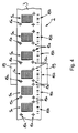
- the microarray 2 is formed band-shaped and magazined on a roll 2a. It has a polymer band as carrier 3, on the surface of which a multiplicity of receptor fields 5a are applied, which are spaced apart from one another in the direction of extension of the carrier 3 marked by the arrow Pf2.
- the receptor fields 5a each have a plurality of receptors 5 and receptor areas, which are arranged in a matrix.
- the roller 2a is rotatably mounted on a holder 25. With the aid of a guide device 26, the microarray 2 is guided from the roller 2a to radiation receivers 24 integrated in a microchip 19 and from these to a take-up device 27.
- a transport device is provided which has transfer elements 28 connected to a drive, which engage in a perforation of the microarray 2.
- the microchip 19 is arranged between the transmission elements 28, so that the microarray 2 is exactly positioned at the radiation receivers 24 of the microchip.
- Fig. 5 forms the container part 15 with the microarray 2 a flow measuring chamber having an inlet opening 29 and an outlet opening 30 on the container part 15.
- the microarray 2 forms a wall of the flow measuring chamber, which seals the receiving space 17 for the sample to the microchip 19 out.
- a seal 31 is arranged, which in the embodiment according to Fig. 5 is designed as a sealing ring.
- the microarray 2 with its rear side facing away from the receiving space 17 directly adjoins the microchip. In this case, the microarray 2 runs approximately parallel to the plane of extent of the microchip 19.
- the radiation receiver 24 are arranged close to the receptors. This allows detection of a ligand with high spatial resolution.
- the microarray 2 has markings 1 5a, by means of which it can be positioned in a predetermined position on the microchip 19.
- sensors integrated for detecting the marks 1 5a which are in control connection with the transport device.
- the microarray 2 has markings 15b which encode the type of receptor field 5a adjacent to the mark 15b.
- a sensor for reading the marks 15b is integrated. The sensor is connected to an evaluation device for processing the coding.
- the device 16 With the device 16, a plurality of receptor fields 5 a can be easily positioned on the receiving space 1 7. The device 16 therefore enables automated performance of a large number of measurements.
- the device 1 for producing a biological microarray 2 which has at least one band-shaped carrier 3 wound onto a roll 3a and having receptors 5 immobilized thereon, each capable of forming a specific binding with a specific ligand 4, thus has a holder 6 with a receptacle 7, on which the roller 3a is rotatably attachable.
- a application device 8 for applying the receptors 5 is arranged on the carrier 3.
- the carrier 3 can be guided by means of a tape guiding device 13 from the receptacle 7 via the application device 8 to a winding device 9.
- the carrier 3 is formed as a moisture-proof polymer film.
- the microarray 2 can seal a receiving space 17 for a sample to be examined against a semiconductor microchip 19 having a sensor for detecting a receptor-ligand complex.
Landscapes
- Health & Medical Sciences (AREA)
- Chemical & Material Sciences (AREA)
- General Health & Medical Sciences (AREA)
- Life Sciences & Earth Sciences (AREA)
- Analytical Chemistry (AREA)
- Immunology (AREA)
- Biochemistry (AREA)
- General Physics & Mathematics (AREA)
- Physics & Mathematics (AREA)
- Pathology (AREA)
- Molecular Biology (AREA)
- Hematology (AREA)
- Clinical Laboratory Science (AREA)
- Chemical Kinetics & Catalysis (AREA)
- Automatic Analysis And Handling Materials Therefor (AREA)
- Investigating, Analyzing Materials By Fluorescence Or Luminescence (AREA)
- Apparatus Associated With Microorganisms And Enzymes (AREA)
Claims (6)
- Microréseau biologique (2) avec un support (3) comportant un film polymère flexible, transparent et étanche à l'humidité, sur lequel sont immobilisés des récepteurs (5), qui sont capables d'entrer en liaison spécifique avec un ligand (4) déterminé, caractérisé en ce qu'une membrane en microfibres est disposée en tant que revêtement sur le film polymère, et en ce que les récepteurs (5) sont appliqués sur la membrane en microfibres.
- Microréseau selon la revendication 1, caractérisé en ce que le support (3) est formé en tant que bande, en ce que les récepteurs (5) sont disposés de façon décalés les uns par rapport aux autres dans le sens d'extension de la bande, et en ce que la bande est emmagasinée de préférence sous la forme d'un rouleau (2a) avec les récepteurs (5), qui y sont appliqués.
- Microréseau selon la revendication 1 ou 2, caractérisé en ce que le rouleau (2a) est disposé dans une cassette de façon à pouvoir tourner autour de son axe, et en ce que la cassette présente un orifice de sortie pour l'extrémité libre du support (3) en forme de bande.
- Microréseau selon l'une des revendications 1 à 3, caractérisé en ce que le support (3) est pourvu de marques (15a, 15b) lisibles par une machine, lesquelles marques présentes au moins des zones, qui sont disposées dans une position prédéterminée par rapport aux récepteurs (5).
- Microréseau selon l'une des revendications 1 à 4, caractérisé en ce que les marques (15a, 15b) présentent un codage destiné à l'identification du type de récepteur (5), qui leur est respectivement attribué et/ou des récepteurs, qui leurs sont respectivement attribués.
- Microréseau selon l'une des revendications 1 à 5, caractérisé en ce que le microréseau (2) présente une perforation pour l'engagement d'un dispositif de transport.
Applications Claiming Priority (2)
| Application Number | Priority Date | Filing Date | Title |
|---|---|---|---|
| DE2002150495 DE10250495A1 (de) | 2002-10-29 | 2002-10-29 | Verfahren und Vorrichtung zum Herstellen eines biologischen Microarrays sowie Vorrichtung zur Detektion eines in einer Probe enthaltenen Liganden |
| EP03773672A EP1543326B1 (fr) | 2002-10-29 | 2003-10-28 | Procede et dispositif pour produire un jeu ordonne de microechantillons biologiques |
Related Parent Applications (2)
| Application Number | Title | Priority Date | Filing Date |
|---|---|---|---|
| EP03773672A Division EP1543326B1 (fr) | 2002-10-29 | 2003-10-28 | Procede et dispositif pour produire un jeu ordonne de microechantillons biologiques |
| EP03773672.5 Division | 2003-10-28 |
Publications (2)
| Publication Number | Publication Date |
|---|---|
| EP2073006A1 EP2073006A1 (fr) | 2009-06-24 |
| EP2073006B1 true EP2073006B1 (fr) | 2013-03-20 |
Family
ID=32114951
Family Applications (3)
| Application Number | Title | Priority Date | Filing Date |
|---|---|---|---|
| EP03773672A Expired - Lifetime EP1543326B1 (fr) | 2002-10-29 | 2003-10-28 | Procede et dispositif pour produire un jeu ordonne de microechantillons biologiques |
| EP09004148A Expired - Lifetime EP2073007B1 (fr) | 2002-10-29 | 2003-10-28 | Dispositif pour la détection d'un ligand dans un échantillon |
| EP09004147A Expired - Lifetime EP2073006B1 (fr) | 2002-10-29 | 2003-10-28 | Micro-réseau biologique flexible |
Family Applications Before (2)
| Application Number | Title | Priority Date | Filing Date |
|---|---|---|---|
| EP03773672A Expired - Lifetime EP1543326B1 (fr) | 2002-10-29 | 2003-10-28 | Procede et dispositif pour produire un jeu ordonne de microechantillons biologiques |
| EP09004148A Expired - Lifetime EP2073007B1 (fr) | 2002-10-29 | 2003-10-28 | Dispositif pour la détection d'un ligand dans un échantillon |
Country Status (4)
| Country | Link |
|---|---|
| EP (3) | EP1543326B1 (fr) |
| AU (1) | AU2003282056A1 (fr) |
| DE (1) | DE10250495A1 (fr) |
| WO (1) | WO2004040303A1 (fr) |
Families Citing this family (2)
| Publication number | Priority date | Publication date | Assignee | Title |
|---|---|---|---|---|
| EP1772731A3 (fr) * | 2005-10-07 | 2007-08-08 | Micronas GmbH | Système de capteur intégré |
| DE102010049807A1 (de) * | 2010-10-27 | 2012-05-03 | Fraunhofer-Gesellschaft zur Förderung der angewandten Forschung e.V. | Verfahren zur Immobilisierung mindestens einer Substanz auf Oberflächen |
Family Cites Families (8)
| Publication number | Priority date | Publication date | Assignee | Title |
|---|---|---|---|---|
| US5922550A (en) * | 1996-12-18 | 1999-07-13 | Kimberly-Clark Worldwide, Inc. | Biosensing devices which produce diffraction images |
| US6197503B1 (en) * | 1997-11-26 | 2001-03-06 | Ut-Battelle, Llc | Integrated circuit biochip microsystem containing lens |
| US6060256A (en) * | 1997-12-16 | 2000-05-09 | Kimberly-Clark Worldwide, Inc. | Optical diffraction biosensor |
| DE10039906A1 (de) * | 1999-08-31 | 2001-04-12 | Inst Mikrotechnik Mainz Gmbh | Vorrichtung und Verfahren zum parallelen oder sequentiellen Untersuchen der Reaktion eines Fluids mit einer Vielzahl von Proben |
| US6399295B1 (en) * | 1999-12-17 | 2002-06-04 | Kimberly-Clark Worldwide, Inc. | Use of wicking agent to eliminate wash steps for optical diffraction-based biosensors |
| WO2001053831A1 (fr) * | 2000-01-17 | 2001-07-26 | Unitec Co., Ltd. | Support integre, micro-recipient integre et membrane permeable, et procede de production et d'utilisation correspondants |
| JP2002218974A (ja) * | 2001-01-24 | 2002-08-06 | Ebara Corp | 反応プローブチップ及び検出システム |
| JP2002286727A (ja) * | 2001-03-28 | 2002-10-03 | Canon Inc | プローブ担体、プローブ担体の製造方法及びそれに用いる装置 |
-
2002
- 2002-10-29 DE DE2002150495 patent/DE10250495A1/de not_active Ceased
-
2003
- 2003-10-28 EP EP03773672A patent/EP1543326B1/fr not_active Expired - Lifetime
- 2003-10-28 WO PCT/EP2003/011965 patent/WO2004040303A1/fr not_active Ceased
- 2003-10-28 EP EP09004148A patent/EP2073007B1/fr not_active Expired - Lifetime
- 2003-10-28 AU AU2003282056A patent/AU2003282056A1/en not_active Abandoned
- 2003-10-28 EP EP09004147A patent/EP2073006B1/fr not_active Expired - Lifetime
Also Published As
| Publication number | Publication date |
|---|---|
| EP2073006A1 (fr) | 2009-06-24 |
| EP2073007A1 (fr) | 2009-06-24 |
| DE10250495A1 (de) | 2004-05-19 |
| AU2003282056A1 (en) | 2004-05-25 |
| EP1543326A1 (fr) | 2005-06-22 |
| AU2003282056A8 (en) | 2004-05-25 |
| EP2073007B1 (fr) | 2011-12-21 |
| WO2004040303A1 (fr) | 2004-05-13 |
| EP1543326B1 (fr) | 2011-11-30 |
Similar Documents
| Publication | Publication Date | Title |
|---|---|---|
| EP0073056B1 (fr) | Bande-test pour analyses et méthode de fabrication | |
| DE4303860C2 (de) | Träger für den kolorimetrischen Gasnachweis in Folienverbundbauweise | |
| DE4014844A1 (de) | Kapillarrohr-spalt-reagensformat | |
| EP3850356B1 (fr) | Procédé pour mesurer une contamination de l'eau potable par des micro-organismes dans une conduite d'eau potable | |
| EP2652479B1 (fr) | Système de mesure pour l'évaluation optique quantitative d'une réaction chimique | |
| EP1990002B1 (fr) | Système de connexion, système de réserve de lancettes, procédé destiné à la fabrication d'un tel système de réserve de lancettes et procédé destiné au positionnement d'éléments fonctionnels disposés sur une bande de transport | |
| EP2116180A1 (fr) | Unité de bande diagnostic et système de mesure diagnostic | |
| DE4205894A1 (de) | Vorrichtung zur erfassung und/oder messung oder kontrolle der beschaffenheit, insbesondere chemischer und/oder biologischer verhaeltnisse mit hilfe von wenigstens einem indikator in fluessigem milieu, insbesondere waessrigem milieu, wie z. b. urin | |
| DE69523656T2 (de) | Verfahren und Vorrichtung zur Probenaufgabe auf trockene analytische Elemente | |
| DE19806054A1 (de) | Testkarte für eine optische oder amperometrische Bestimmung der Konzentration einer Substanz in einer Flüssigkeit | |
| EP2073006B1 (fr) | Micro-réseau biologique flexible | |
| DE69421581T2 (de) | Fluoreszenz-Messverfahren der volumetrischen Leistung einer mit Zellen gravierten Oberfläche | |
| EP1715319B1 (fr) | Procédé de détermination de la distribution de pression sur une surface et peinture sensible à la pression utilisée dans ce but | |
| WO2004031747A1 (fr) | Procede et dispositif de detection d'au moins une matiere luminescente | |
| WO2016062456A1 (fr) | Procédé et dispositif de determination d'au moins un paramètre d'un matériau d'analyse dans un tampon analyse à l'aide d'une chambre de réaction | |
| EP1682892A1 (fr) | Procede et dispositif de detection d'analytes | |
| EP3850357A1 (fr) | Système de cartouche interchangeable | |
| AT526980A1 (de) | Verfahren zur messung der kaliumkonzentration einer blutprobe | |
| EP1517753B1 (fr) | Procede et dispositif pour determiner la concentration de ligands contenus dans un echantillon liquide | |
| EP1930716A1 (fr) | Procédé et dispositif destinés à la détection d'un ligand dans un fluide | |
| WO2007076949A1 (fr) | Puce de capteur avec récepteur empilé à réseau polymère |
Legal Events
| Date | Code | Title | Description |
|---|---|---|---|
| PUAI | Public reference made under article 153(3) epc to a published international application that has entered the european phase |
Free format text: ORIGINAL CODE: 0009012 |
|
| 17P | Request for examination filed |
Effective date: 20090324 |
|
| AC | Divisional application: reference to earlier application |
Ref document number: 1543326 Country of ref document: EP Kind code of ref document: P |
|
| AK | Designated contracting states |
Kind code of ref document: A1 Designated state(s): CH DE FR GB IT LI NL |
|
| AKX | Designation fees paid |
Designated state(s): CH DE FR GB IT LI NL |
|
| RAP1 | Party data changed (applicant data changed or rights of an application transferred) |
Owner name: ENDRESS+HAUSER CONDUCTA GESELLSCHAFT FUER MESS- UN |
|
| GRAP | Despatch of communication of intention to grant a patent |
Free format text: ORIGINAL CODE: EPIDOSNIGR1 |
|
| RIC1 | Information provided on ipc code assigned before grant |
Ipc: G01N 21/86 20060101ALI20121019BHEP Ipc: G01N 21/62 20060101ALI20121019BHEP Ipc: G01N 21/84 20060101ALI20121019BHEP Ipc: B01L 3/00 20060101ALI20121019BHEP Ipc: G01N 35/00 20060101ALI20121019BHEP Ipc: G01N 33/53 20060101AFI20121019BHEP |
|
| RIC1 | Information provided on ipc code assigned before grant |
Ipc: G01N 21/84 20060101ALI20121022BHEP Ipc: G01N 21/86 20060101ALI20121022BHEP Ipc: G01N 35/00 20060101ALI20121022BHEP Ipc: B01L 3/00 20060101ALI20121022BHEP Ipc: G01N 21/64 20060101ALI20121022BHEP Ipc: G01N 33/53 20060101AFI20121022BHEP |
|
| GRAS | Grant fee paid |
Free format text: ORIGINAL CODE: EPIDOSNIGR3 |
|
| GRAA | (expected) grant |
Free format text: ORIGINAL CODE: 0009210 |
|
| AC | Divisional application: reference to earlier application |
Ref document number: 1543326 Country of ref document: EP Kind code of ref document: P |
|
| AK | Designated contracting states |
Kind code of ref document: B1 Designated state(s): CH DE FR GB IT LI NL |
|
| REG | Reference to a national code |
Ref country code: GB Ref legal event code: FG4D Free format text: NOT ENGLISH |
|
| REG | Reference to a national code |
Ref country code: CH Ref legal event code: EP |
|
| REG | Reference to a national code |
Ref country code: DE Ref legal event code: R096 Ref document number: 50314735 Country of ref document: DE Effective date: 20130516 |
|
| REG | Reference to a national code |
Ref country code: NL Ref legal event code: VDEP Effective date: 20130320 |
|
| PG25 | Lapsed in a contracting state [announced via postgrant information from national office to epo] |
Ref country code: NL Free format text: LAPSE BECAUSE OF FAILURE TO SUBMIT A TRANSLATION OF THE DESCRIPTION OR TO PAY THE FEE WITHIN THE PRESCRIBED TIME-LIMIT Effective date: 20130320 |
|
| PLBE | No opposition filed within time limit |
Free format text: ORIGINAL CODE: 0009261 |
|
| STAA | Information on the status of an ep patent application or granted ep patent |
Free format text: STATUS: NO OPPOSITION FILED WITHIN TIME LIMIT |
|
| 26N | No opposition filed |
Effective date: 20140102 |
|
| PG25 | Lapsed in a contracting state [announced via postgrant information from national office to epo] |
Ref country code: IT Free format text: LAPSE BECAUSE OF FAILURE TO SUBMIT A TRANSLATION OF THE DESCRIPTION OR TO PAY THE FEE WITHIN THE PRESCRIBED TIME-LIMIT Effective date: 20130320 |
|
| REG | Reference to a national code |
Ref country code: DE Ref legal event code: R097 Ref document number: 50314735 Country of ref document: DE Effective date: 20140102 |
|
| REG | Reference to a national code |
Ref country code: CH Ref legal event code: PL |
|
| GBPC | Gb: european patent ceased through non-payment of renewal fee |
Effective date: 20131028 |
|
| PG25 | Lapsed in a contracting state [announced via postgrant information from national office to epo] |
Ref country code: CH Free format text: LAPSE BECAUSE OF NON-PAYMENT OF DUE FEES Effective date: 20131031 Ref country code: GB Free format text: LAPSE BECAUSE OF NON-PAYMENT OF DUE FEES Effective date: 20131028 Ref country code: LI Free format text: LAPSE BECAUSE OF NON-PAYMENT OF DUE FEES Effective date: 20131031 |
|
| REG | Reference to a national code |
Ref country code: FR Ref legal event code: ST Effective date: 20140630 |
|
| PG25 | Lapsed in a contracting state [announced via postgrant information from national office to epo] |
Ref country code: FR Free format text: LAPSE BECAUSE OF NON-PAYMENT OF DUE FEES Effective date: 20131031 |
|
| PGFP | Annual fee paid to national office [announced via postgrant information from national office to epo] |
Ref country code: DE Payment date: 20151022 Year of fee payment: 13 |
|
| REG | Reference to a national code |
Ref country code: DE Ref legal event code: R119 Ref document number: 50314735 Country of ref document: DE |
|
| PG25 | Lapsed in a contracting state [announced via postgrant information from national office to epo] |
Ref country code: DE Free format text: LAPSE BECAUSE OF NON-PAYMENT OF DUE FEES Effective date: 20170503 |