EP2073036B1 - Procédé de mesure de portée, appareil de mesure de portée, système de mesure de portée et programme de mesure de portée - Google Patents
Procédé de mesure de portée, appareil de mesure de portée, système de mesure de portée et programme de mesure de portée Download PDFInfo
- Publication number
- EP2073036B1 EP2073036B1 EP08254035A EP08254035A EP2073036B1 EP 2073036 B1 EP2073036 B1 EP 2073036B1 EP 08254035 A EP08254035 A EP 08254035A EP 08254035 A EP08254035 A EP 08254035A EP 2073036 B1 EP2073036 B1 EP 2073036B1
- Authority
- EP
- European Patent Office
- Prior art keywords
- frequency
- signal
- range
- rfid tag
- response signal
- Prior art date
- Legal status (The legal status is an assumption and is not a legal conclusion. Google has not performed a legal analysis and makes no representation as to the accuracy of the status listed.)
- Active
Links
Images




Classifications
-
- G—PHYSICS
- G01—MEASURING; TESTING
- G01S—RADIO DIRECTION-FINDING; RADIO NAVIGATION; DETERMINING DISTANCE OR VELOCITY BY USE OF RADIO WAVES; LOCATING OR PRESENCE-DETECTING BY USE OF THE REFLECTION OR RERADIATION OF RADIO WAVES; ANALOGOUS ARRANGEMENTS USING OTHER WAVES
- G01S13/00—Systems using the reflection or reradiation of radio waves, e.g. radar systems; Analogous systems using reflection or reradiation of waves whose nature or wavelength is irrelevant or unspecified
- G01S13/74—Systems using reradiation of radio waves, e.g. secondary radar systems; Analogous systems
- G01S13/82—Systems using reradiation of radio waves, e.g. secondary radar systems; Analogous systems wherein continuous-type signals are transmitted
- G01S13/84—Systems using reradiation of radio waves, e.g. secondary radar systems; Analogous systems wherein continuous-type signals are transmitted for distance determination by phase measurement
Definitions
- the present invention relates to a range measuring method, a range measuring apparatus, a non-contacted IC medium, a range measuring system and a range measuring program, which measures a range, for example, from a reader unit to a non-contacted IC medium.
- the range measuring apparatus controls an RFID tag (non-contacted IC medium) to transmit two times a R/W request signal that requests transmission of a tag response signal.
- a frequency controller controls a PLL portion to transmit respective R/W request signals by transfer frequencies differing from each other.
- a phase information acquisition portion detects fluctuation amounts in phase of tag response signals transmitted by the transfer frequencies differing from each other, respectively, and calculates the range between a reader/writer and the RFID tag based on the fluctuation amounts in the phase. Therefore, the range between the reader/writer and the RFID tag can be accurately calculated.
- the non-contacted IC medium always stops at a fixed position. And, there is a case where the range to a non-contacted IC medium in motion is requested to be obtained. In such a case, since the above-described range measuring apparatus carries out transmission and receiving of different frequencies at different timings, a deviation occurs at the receiving timing. Therefore, where the non-contacted IC medium is conveyed at a high speed, it is difficult to accurately calculate the range.
- WO 87/03698 discloses an apparatus and method for measuring distances in which a modulated response signal from a transponder is mixed down with a transmitted frequency and (a) filtered to form a first measuring signal, and (b) demodulated to form a second measuring signal. The phases of the first and second measuring signals are compared to obtain a distance measurement.
- EP 1 225 422 discloses a process and system for measuring the distance of a moving body from a fixed part from the sum of a signal produced on the fixed part and a signal returned from the moving body in response to a signal emitted by the fixed part.
- US 2002/0008615 discloses an anti-theft protection system in which the distance between a portable code transmitter and a vehicle-based transmitting and receiving unit is determined by analysing echo signals in the frequency spectrum of a measurement signal obtained by mixing a broadband transmitted signal with a modulated reflected signal.
- a preferred aim of the invention is to provide a range measuring method, a range measuring apparatus, a non-contacted IC medium, a range measuring system and a range measuring program, which are capable of carrying out highly accurate range measurements even if a non-contacted IC medium is in motion.
- a method of measuring a range from a reader unit to a Radio Frequency Identification (RFID) tag comprising: transmitting an inquiry signal at a single first frequency from the reader unit to the RFID tag; performing modulation at the RFID tag to modulate the first frequency by using a second frequency to obtain a modulated frequency, and responding to the inquiry signal at the RFID tag by returning a response signal at the modulated frequency, the response signal comprising an upper side band (USB) signal component and lower side band (LSB) signal component; and receiving the response signal at the reader unit; acquiring at the reader unit a plurality of frequency components of the response signal by extracting I and Q components from the response signal; calculating from the extracted I and Q components a phase difference between the upper side band (USB) signal component and lower side band (LSB) signal component; and measuring the range by using the calculated phase difference.
- RFID Radio Frequency Identification
- Phase shift keying may be used for the modulation.
- Frequency shift keying may be used for the modulation.
- the modulation may be digital modulation, and the plurality of frequency components may be high frequency components generated in the digital modulation.
- the response signal may be separated into an upper side band and a lower side band in order to acquire the plurality of frequency components.
- apparatus operable to measure a range from a reader unit to a Radio Frequency Identification (RFID) tag
- RFID Radio Frequency Identification
- the apparatus comprising: a communication unit, transmitting an inquiry signal at a single first frequency from the reader unit to the RFID tag, and receiving a response signal from the RFID tag, the response signal having a modulated frequency obtained by modulating the first frequency using a second frequency and comprising an upper side band (USB) signal component and lower side band (LSB) signal component; a frequency component acquiring unit, acquiring a plurality of frequency components of the response signal by extracting I and Q components from the response signal; and a range measuring unit, calculating from the extracted I and Q components a phase difference between the upper side band (USB) signal component and lower side band (LSB) signal component, and measuring the range by using the calculated phase difference.
- a communication unit transmitting an inquiry signal at a single first frequency from the reader unit to the RFID tag, and receiving a response signal from the RFID tag, the response signal having a modulated frequency
- a range measuring system comprising a Radio Frequency Identification (RFID) tag including a communication unit, receiving an inquiry signal at a single first frequency from a reader unit, and returning a response signal to the reader unit; and a modulation unit, performing modulation to modulate the first frequency by using a second frequency to obtain a modulated frequency, wherein the communication unit returns the response signal at the modulated frequency; and an apparatus as described above, operable to measure a range from the reader unit to the RFID tag.
- RFID Radio Frequency Identification
- a range measuring program for causing a reader unit, which includes a communication unit communicating with a Radio Frequency Identification (RFID) tag and a control unit carrying out various types of control, to execute: an inquiry process for transmitting an inquiry signal to the RFID tag at a single first frequency by the communication unit; a response signal receiving process for receiving a response signal from the RFID tag, the response signal having a modulated frequency obtained by modulating the first frequency using a second frequency and comprising an upper side band (USB) signal component and lower side band (LSB) signal component; a frequency component acquiring process for acquiring a plurality of frequency components of the received response signal by extracting I and Q components from the response signal; and a range measuring process for calculating from the extracted I and Q components a phase difference between the upper side band (USB) signal component and lower side band (LSB) signal component and measuring a range from the reader unit to the RFID tag by using the calculated phase difference.
- RFID Radio Frequency Identification
- the inquiry signal may be made into a signal for which the reader unit causes the non-contacted IC medium to respond, and for example, may be made into a signal including a command to send an ID.
- the response signal may be made into a signal for which the non-contacted IC medium responds to the reader unit, and for example, may be made into a signal to send an ID.
- the frequency component acquiring unit may be a unit for acquiring, for example, frequency components while separating the same into USB components and LSB components, and may be composed as a unit for acquiring frequencies with the same separated as per component.
- the range measuring unit may be composed of a unit for measuring a range by per-component frequencies, and may be composed of a unit for calculating appropriately using numerical expressions.
- the range measuring apparatus may be made into a reader unit that can communicate with a non-contacted IC medium.
- the inquiry process may be made into a process for transmitting an inquiry signal to inquire about an ID, etc., to a non-contacted IC medium.
- the response signal receiving process may be made into a process for receiving a response signal from the non-contacted IC medium.
- the frequency component acquiring process may be composed of a process for separating a response signal into components of different frequencies.
- the range measuring process may be composed of a process for measuring a range by calculation expressions.
- Fig. 1 is a configuration view of a range measuring system 1
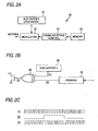
- Figs. 2A to 2C are schematic views of a configuration of an RFID tag (Radio Frequency Identification Tag) 20
- Figs. 3A and 3B are schematic views of a configuration of reader/writer 10.
- the range measuring system 1 is composed of a reader/writer 10 and an RFID tag 20.
- the RFID tag 20 is provided with a sub carrier generation portion 22, a modulation portion 23, a communications controller 24 and a memory portion 25 in addition to an antenna 21 as shown in Fig. 2A .
- the antenna 21 communicates with the reader/writer 10 in a non-contacted state.
- the antenna may be composed of an appropriate antenna such as a UHF antenna or a loop antenna.
- the sub carrier generation portion 22 generates a sub carrier (sub carrier wave) whose frequency is different from the first frequency (frequency fc) used by the reader/writer 10 as a carrier wave.
- a sub carrier sub carrier wave
- PSK phase shift keying
- FSK frequency shift keying
- a lower frequency than the first frequency is adopted for the sub carrier.
- the memory portion 25 stores ID being identification information of the RFID tag 20 and other data.
- the communications controller 24 carries out communications control by which it receives a command from the reader/writer 10, modulates digital data in the memory portion 25 and responds to the reader/writer 10.
- the communications controller 24 is composed of digital circuits (logic) to execute parallel processing such as sub carrier generation.
- the modulation portion 23 modulates the sub carrier based on digital data transmitted from the communications controller 24. It is composed so that the modulation is selectively carried out based on two types of PSK and FSK.
- the calculator 26 obtains an exclusive logic sum (XOR: exclusive or) of the sub carrier 28 (sub carrier wave shown at [1] in Fig. 2C ) and digital data (data shown at [2] in Fig. 2C ) that is framed by adding a preamble and CRC (Cyclic Redundancy Check), etc., in a framing portion 29, and an after-calculated signal (signal shown at [3] in Fig. 2C ) is generated.
- reflected signals of the first frequency fc which are from the reader/writer 10
- the antenna 21 become a response to the reader/writer 10.
- output signals are generated by changing a sub carrier 28a and a sub carrier 28b by a multiplexer 27 (MUX) using the sub carrier 28a (sub carrier wave shown at [1] in Fig. 3B ), sub carrier 28b (sub carrier wave shown at [2] in Fig. 3B ) and digital data (data shown at [3] in Fig. 3B ) framed by adding a preamble and a CRC thereto at the framing portion 29. And, the signals are sent back from the antenna 21 to the reader/writer 10.
- MUX multiplexer 27
- the RFID tag 20 is provided with a demodulator and a decoder (illustration of which is omitted).
- the demodulator demodulates signals received by the antenna 21 and acquires command signals transmitted from the reader/writer 10.
- the decoder decodes demodulated command signals, and takes out coded command data, wherein processes of reading (transmitting a designated area of the memory portion 25) and writing (writing data following the command in the designated area of the memory portion 25) are carried out.
- the RFID tag 20 there are two types, one of which is a passive type that does not have any power source and responds to actuation by an electric field or magnetic field and the other of which is a semi-passive type that internally includes a power source and responds when receiving a response request from the reader/writer 10. Therefore, the RFID tag 20 can synchronize with carrier waves transmitted from the reader/writer 10.
- the reader/writer 10 is provided with the antenna 11, and is also provided with a controller and a memory portion, illustration of which is omitted.
- the memory portion stores various types of data and also stores a range measuring program to measure the range.
- the reader/writer 10 includes a range calculating portion 13, a frequency component separating portion 14 and a frequency converting portion 15 as shown in Fig. 4A .
- the frequency converting portion 15 carries out frequency conversion in regard to signals received from the antenna 11, and sends the frequency component ( ⁇ fs) of a sub carrier to the frequency component separating portion 14.
- the frequency component separating portion 14 separates the received frequency component ( ⁇ fs) into USB and LSB.
- the LSB can be picked up by the configuration shown in Fig 4B . That is, first, I components and Q components are extracted from input frequencies by means of an orthogonal mixer 14a, wherein the phase of the Q components is changed by +90° by a phase converter 14b. And, the after-phase changed Q component and I components for which the phase has not been changed are synthesized by a synthesizer 14c, thereby extracting the LSB.
- USB can be picked up by the configuration shown in Fig. 4C . That is, first, I components and Q components are extracted from input frequencies by an orthogonal mixer 14a, wherein the phase of the Q components is changed by -90° by a phase converter 14d. And, the after-phase changed Q component and I components for which the phase has not been changed are synthesized by a synthesizer 14c, thereby extracting the USB.
- the range calculating portion 13 shown in Fig. 4A calculates the range using the USB and LSB that are extracted by the frequency component separating portion 14.
- the range calculation is carried out as follows.
- the phase of the signal of the first frequency fc transmitted by the reader/writer 10 is the reference phase
- the signals of the first frequency fc reach the RFID tag 20 located at a distance r from the reader/writer 10 and is reflected therefrom, and phase of carrier waves returned to the reader/writer 10 becomes ⁇ t.
- the phase ⁇ ru of the USB signal which is generated by modulation with respect to the signal of the first frequency fc at the RFID tag 20 and has reached the reader/writer 10
- the phase ⁇ rl of the LSB signal for the reference phase may be expressed by the following expression.
- Figs. 5A to 5C are schematic views describing a carrier wave, a response signal, USB and LSB where PSK is used.
- an inquiry signal (carrier wave) transmitted by the reader/writer 10 is a signal of the first frequency fc.
- the response signal (reflected wave) responded by the RFID tag 20 is a signal obtained by synthesizing the first frequency fc and the second frequency fs.
- data are expressed in the PSK system.
- the response signal can pick up USB and LSB by separation of frequency components.
- Figs. 6A and 6B are schematic views describing a carrier wave, a response signal, USB and LSB where FSK is used.
- a response signal (reflected wave) that the RFID tag 20 responds to is a signal-obtained by synthesizing the first frequency fc and the second frequency fs and the third frequency fs2, which are sub carriers.
- data are expressed in the FSK system.
- the response signal may obtain a number of components separated into USB and LSB and separated into the second frequency fs1 component and the third frequency fs2 component by separation of frequency components.
- three or more frequency components may be used, wherein a high-resolution power algorithm based on the MUSIC (Multiple Signal Classification) method disclosed by the International Publication WO2006/095463 etc., may be used. Accordingly, the accuracy under multi-pass environments can be improved with transmission frequency from the reader/writer 10 remaining as one frequency.
- MUSIC Multiple Signal Classification
- Fig. 7 is a flowchart showing actions when a range from the reader/writer 10 to the RFID tag 20 is obtained by the range measuring system 1.
- the reader/writer 10 carries out command transmission and requests a response for ID from the RFID tag 20 (Step S1). At this time, the command is transmitted by the first frequency fc. Also, the command includes a modulation system code to determine whether the modulation system is based on PSK or FSK.
- the RFID tag 20 analyzes the command from the reader/writer 10 (Step S2) and extracts the modulation system code.
- Step S4 PSK
- the RFID tag 20 changes the modulation portion 23 to the PSK circuit (Step S5).
- Step S4 FSK
- the RFID tag 20 changes the modulation portion 23 to the FSK circuit (Step S6).
- the RFID tag 20 reads memory data stored in the memory 25 (this example includes ID) (Step S7), and frames by adding a preamble and CRC thereto (Step S8).
- the RFID tag 20 modulates framed data by the system (PSK or FSK) changed by Steps S4 through S6 (Step S9), and sends back a response signal (Response) (Step S10).
- the reader/writer 10 receives a response signal (Response) (Step S11), and detects whether or not there is any error, by a CRC check (redundancy cyclic inspection) (Step S12).
- Step S12 If any error occurs (Step S12: NG), the reader/writer 10 returns the process to Step S1, and carries out the process again.
- Step S12 If there is no error (Step S12: OK), the reader/writer 10 carries out a process of FFT (Fast Fourier Transform) of the received signal by the frequency converting portion 15 (Step S13).
- FFT Fast Fourier Transform
- the reader/writer 10 further separates LSB and USB from each other by the frequency component separating portion 14 (Step S14), calculates a phase by the range calculating portion 13 (Step S15), and carries out estimation of the range based on the phase difference (Step S16).
- the reader/writer 10 combines the calculated range with an ID included in the signals received in Step S11 and outputs the same (Step S17), and then terminates the process. Also, the output may be carried out by an appropriate method such as storing the output in a memory unit of the reader/writer 10, transmitting the same to another device connected to the reader/writer 10 or displaying the same in a display device secured at the reader/writer 10.
- the reader/writer 10 receives a response signal including multiple frequency components from the RFID tag 20, and can calculate the range from the reader/writer 10 to the RFID tag 20.
- the RFID tag 20 returns reflected waves (response signals) with respect to a single frequency transmitted from the reader/writer 10, using frequency components, wherein the measurement accuracy can be improved by using multiple frequencies.
- PSK and FSK are used, the frequency separation is not limited thereto, but various methods may be used to separate frequencies to enable range measurement.
- the modulating portion 23 of the RFID tag 20 carries out modulation in the PSK system.
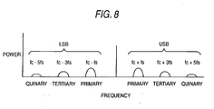
- the reader/writer 10 extracts high frequency components (odd-number order such as primary, tertiary, quinary, etc.) as shown in Fig. 8 , and these high frequency components may be used.
- a high-resolution power algorithm based on the MUSIC method may be utilized. Therefore, the accuracy under a multiple-pass environment can be improved with the transmission frequency from the reader/writer 10 remaining as one frequency.
- the RFID tag 20 is of a semi-passive type having a power source. Accordingly, power necessary to pick up high frequencies can be secured, and can be effectively utilized.
- the frequency component separating portion 14 uses a complex FFT operation.
- received signals are separated into I signals and Q signals by the orthogonal mixer 14a, and the respective signals may be separated into real parts and imaginary parts by complex FFT operations 14e and 14f.
- USB components and LSB components for which addition and subtraction are further carried out are extracted, and phases of USB and LSB may be calculated from the respective I components and Q components.
- the respective phases of USB and LSB may be obtained by the following mathematical expressions.
- Phase delay of USB ⁇ ru Arctan ⁇ FFT ⁇ I Re + FFT ⁇ Q Im / FFT ⁇ I Im + FFT ⁇ Q Re * FFT ⁇ I Re : Real part separated from I signals by complex FFT operation
- FFT ⁇ I Im Imaginary part separated from I signals by complex FFT operation
- FFT ⁇ Q Re Real part separated from Q signals by complex FFT operation
- FFT ⁇ Q Im Imaginary part separated from Q signals by complex FFT operation
- Arctan X Function from calculation of arc - tangent of X
- FFT ⁇ I Im Imaginary part separated from I signals by complex FFT
- the reader/writer 10 receives a response signal from the RFID tag 20 corresponding thereto, and can calculate the range from the reader/writer 10 to the RFID tag 20.
- the RFID tag 20 may be composed so as to function as a sensing device.
- the RFID tag 20 may be equipped with an appropriate sensor such as a temperature sensor, a humidity sensor, etc., instead of the memory portion 25 or connecting thereto. And, it may be composed that the RFID tag 20 frames a measurement value of the corresponding sensor as data, modulates the same and responds to the reader/writer.
- the reader/writer 10 can acquire sensing information in a non-contacted state, and is able to recognize by range calculation at which position (range) the sensing information has been obtained.
- composition of the invention matches or corresponds to the above-described embodiment as shown below;
- the range measuring system according to the invention matches or corresponds to a range measuring system 1 according to the embodiment.
- the reader unit and range measuring apparatus match or correspond to the reader/writer 10
- the communication unit matches or corresponds to the antenna 11
- the range measuring unit matches or corresponds to the range calculating portion 13
- the frequency component acquiring unit matches or corresponds to the frequency component separating portion 14
- the non-contacted IC medium matches or corresponds to the RFID tag 20
- the communications unit matches or corresponds to the antenna 21
- the modulating unit matches or corresponds to the modulating portion 23
- the inquiry process matches or corresponds to Step S1
- the inquiry signal receiving process matches or corresponds to Step S2
- the response signal receiving process matches or corresponds to Step S11
- the frequency component acquiring process matches or corresponds to Steps S13 and S14
- the range measuring process matches or corresponds to Steps S15 and S16.
- the invention is not limited to only the composition of the above-described embodiment, but may be subjected to various embodiments.
- a range measuring method it is possible to provide a range measuring method, a range measuring apparatus, a non-contacted IC medium, a range measuring system and a range measuring program, which are capable of executing highly accurate range measurements even if the non-contacted IC medium is in motion.
Landscapes
- Engineering & Computer Science (AREA)
- Radar, Positioning & Navigation (AREA)
- Remote Sensing (AREA)
- Computer Networks & Wireless Communication (AREA)
- Physics & Mathematics (AREA)
- General Physics & Mathematics (AREA)
- Near-Field Transmission Systems (AREA)
- Radar Systems Or Details Thereof (AREA)
Claims (8)
- Procédé de mesure d'une plage d'une unité de lecteur (10) à une étiquette d'identification radiofréquence, RFID, (20), le procédé consistant à :émettre un signal d'interrogation à une première fréquence (fc) unique de l'unité de lecteur (10) vers l'étiquette RFID (20) ;effectuer une modulation au niveau de l'étiquette RFID (20) pour moduler la première fréquence (fc) en utilisant une deuxième fréquence (fs) pour obtenir une fréquence modulée, et répondre au signal d'interrogation au niveau de l'étiquette RFID (20) en renvoyant un signal de réponse à la fréquence modulée, le signal de réponse comprenant une composante de signal de bande latérale supérieure, USB, et une composante de signal de bande latérale inférieure, LSB ; etrecevoir le signal de réponse au niveau de l'unité de lecteur,caractérisé par :l'acquisition, au niveau de l'unité de lecteur, d'une pluralité de composantes de fréquence du signal de réponse en extrayant les composantes I et Q du signal de réponse ;le calcul (S15), à partir des composantes I et Q extraites, d'une différence de phase entre la composante de signal USB et la composante de signal LSB ; etla mesure (S16) de la plage en utilisant la différence de phase calculée.
- Procédé selon la revendication 1, dans lequel une modulation par déplacement de phase est utilisée pour la modulation.
- Procédé selon la revendication 1, dans lequel une modulation par déplacement de fréquence est utilisée pour la modulation.
- Procédé selon l'une quelconque des revendications 1, 2 et 3, dans lequel
la modulation est une modulation numérique, et
la pluralité de composantes de fréquence sont des composantes haute fréquence générées dans la modulation numérique. - Procédé selon l'une quelconque des revendications 1 à 4, dans lequel le signal de réponse est séparé en une bande latérale supérieure et une bande latérale inférieure afin d'acquérir la pluralité de composantes de fréquence.
- Appareil, pouvant être utilisé pour mesurer une plage d'une unité de lecteur (10) à une étiquette RFID (20), l'appareil comprenant :une unité de communication (11), émettant un signal d'interrogation à une première fréquence (fc) unique de l'unité de lecteur (10) vers l'étiquette RFID (20), et recevant un signal de réponse de l'étiquette RFID, le signal de réponse ayant une fréquence modulée obtenue en modulant la première fréquence (fc) en utilisant une deuxième fréquence (fs) et comprenant une composante de signal USB et une composante de signal LSB ; etcaractérisé par :une unité d'acquisition de composante de fréquence (14), acquérant une pluralité de composantes de fréquence du signal de réponse en extrayant les composantes I et Q du signal de réponse ; etune unité de mesure de plage (13), calculant, à partir des composantes I et Q extraites, une différence de phase entre la composante de signal USB et la composante de signal LSB, et mesurant la plage en utilisant la différence de phase calculée.
- Système de mesure de plage, comprenant :une étiquette RFID (20) comprenant :une unité de communication, recevant un signal d'interrogation à une première fréquence (fc) d'une unité de lecteur (10), et renvoyant un signal de réponse à l'unité de lecteur ; etune unité de modulation (23), effectuant une modulation pour moduler la première fréquence (fc) en utilisant une deuxième fréquence (fs) pour obtenir une fréquence modulée,dans lequel l'unité de communication renvoie le signal de réponse à la fréquence modulée ; etun appareil selon la revendication 6, pouvant être utilisé pour mesurer une plage de l'unité de lecteur (10) à l'étiquette RFID (20).
- Programme de mesure de plage pour amener une unité de lecteur (10), qui comprend une unité de communication (11) communiquant avec une étiquette RFID (20) et une unité de commande effectuant divers types de commandes, à exécuter :un processus d'interrogation pour émettre un signal d'interrogation vers l'étiquette RFID (20) à une première fréquence (fc) unique par l'unité de communication (11) ; etun processus de réception de signal de réponse pour recevoir un signal de réponse de l'étiquette RFID (20), le signal de réponse ayant une fréquence modulée obtenue en modulant la première fréquence (fc) en utilisant une deuxième fréquence (fs) et comprenant une composante de signal de bande latérale supérieure, USB, et une composante de signal de bande latérale inférieure, LSB, etcaractérisé par :un processus d'acquisition de composante de fréquence (S14) pour acquérir une pluralité de composantes de fréquence du signal de réponse reçu en extrayant les composantes I et Q du signal de réponse ; etun processus de mesure de plage pour calculer (S15), à partir des composantes I et Q extraites, une différence de phase entre la composante de signal USB et la composante de signal LSB et mesurer (S16) une plage de l'unité de lecteur (10) à l'étiquette RFID (20) en utilisant la différence de phase calculée.
Applications Claiming Priority (1)
| Application Number | Priority Date | Filing Date | Title |
|---|---|---|---|
| JP2007325887A JP2009145300A (ja) | 2007-12-18 | 2007-12-18 | 距離測定方法、距離測定装置、非接触ic媒体、距離測定システム、および距離測定プログラム |
Publications (2)
| Publication Number | Publication Date |
|---|---|
| EP2073036A1 EP2073036A1 (fr) | 2009-06-24 |
| EP2073036B1 true EP2073036B1 (fr) | 2012-06-13 |
Family
ID=40513814
Family Applications (1)
| Application Number | Title | Priority Date | Filing Date |
|---|---|---|---|
| EP08254035A Active EP2073036B1 (fr) | 2007-12-18 | 2008-12-17 | Procédé de mesure de portée, appareil de mesure de portée, système de mesure de portée et programme de mesure de portée |
Country Status (4)
| Country | Link |
|---|---|
| US (1) | US8149155B2 (fr) |
| EP (1) | EP2073036B1 (fr) |
| JP (1) | JP2009145300A (fr) |
| CN (1) | CN101464517A (fr) |
Families Citing this family (14)
| Publication number | Priority date | Publication date | Assignee | Title |
|---|---|---|---|---|
| GB0709313D0 (en) * | 2007-05-15 | 2007-06-20 | Siemens Ag | RFID reader |
| WO2011054128A1 (fr) * | 2009-11-03 | 2011-05-12 | 北京简约纳电子有限公司 | Dispositif et procédé pour mesurer précisément la distance de communication en champ proche d'une étiquette d'identification par radiofréquence (rfid) |
| US8823577B2 (en) * | 2009-12-23 | 2014-09-02 | Itrack, Llc | Distance separation tracking system |
| EP2407799B1 (fr) * | 2010-07-16 | 2018-04-11 | Sivers Ima AB | Procédé et dispositif pour des mesures de radar à onde continue |
| JP5887539B2 (ja) * | 2010-09-14 | 2016-03-16 | パナソニックIpマネジメント株式会社 | レーダ装置 |
| US9911018B1 (en) | 2012-01-12 | 2018-03-06 | Impinj, Inc. | RFID tags with digital signature subportions |
| US11361174B1 (en) | 2011-01-17 | 2022-06-14 | Impinj, Inc. | Enhanced RFID tag authentication |
| US8723720B2 (en) * | 2011-05-03 | 2014-05-13 | Harris Corporation | Wireless location detection and/or tracking device and associated methods |
| CN102957453B (zh) * | 2011-08-25 | 2016-03-30 | 国民技术股份有限公司 | 一种基于磁通信的射频sim卡的通信方法及系统 |
| US9349029B2 (en) * | 2012-07-11 | 2016-05-24 | Tag-Comm Inc. | Transmission apparatus for a wireless device |
| KR20170060089A (ko) | 2014-09-22 | 2017-05-31 | 디알엔씨 홀딩스, 인크. | 델타-시그마 변조를 사용하는 무선 디바이스용 송신 장치 |
| JP7119369B2 (ja) * | 2017-12-21 | 2022-08-17 | 株式会社アイシン | 距離計測装置 |
| US11175402B2 (en) * | 2019-11-25 | 2021-11-16 | Texas Instruments Incorporated | Time-varying template for improved short-distance performance in coded ultrasonic ranging |
| JP7029147B2 (ja) * | 2020-12-25 | 2022-03-03 | 株式会社東海理化電機製作所 | 電波伝搬距離推定システム |
Citations (7)
| Publication number | Priority date | Publication date | Assignee | Title |
|---|---|---|---|---|
| EP0730251A2 (fr) * | 1995-03-03 | 1996-09-04 | Mitsubishi Denki Kabushiki Kaisha | Carte à circuit intégré sans contact, système et méthode de transmission pour une telle carte |
| WO2000045328A1 (fr) * | 1999-01-26 | 2000-08-03 | Koninklijke Philips Electronics N.V. | Porteuse de donnees pourvue d'au moins deux etages de decodage |
| WO2001094974A2 (fr) * | 2000-06-06 | 2001-12-13 | Battelle Memorial Institute | Mesure de distance par determination d'un delta de phase rf |
| US20020008615A1 (en) * | 1999-11-30 | 2002-01-24 | Patric Heide | Anti-theft protection system for a motor vehicle, and a method for operating an anti-theft protection system |
| US20020080864A1 (en) * | 1999-01-29 | 2002-06-27 | Jurgen Kuttruff | Contactless data transmission system and method for contactless data transmission |
| US20040213169A1 (en) * | 2001-10-23 | 2004-10-28 | Inside Contactless | Contact-free integrated circuit having automatic frame identification means |
| WO2007018162A1 (fr) * | 2005-08-11 | 2007-02-15 | Semiconductor Energy Laboratory Co., Ltd. | Dispositif à semi-conducteur et système de transmission sans fil |
Family Cites Families (21)
| Publication number | Priority date | Publication date | Assignee | Title |
|---|---|---|---|---|
| DE1252277B (fr) * | 1963-08-19 | |||
| JPS511558B1 (fr) * | 1970-12-30 | 1976-01-19 | ||
| SE456118B (sv) | 1985-12-12 | 1988-09-05 | Stiftelsen Inst Mikrovags | Forfarande och anordning for att meta avstand mellan ett forsta och ett andra foremal med signaler av mikrovagsfrekvens |
| JP2516131B2 (ja) * | 1992-01-20 | 1996-07-10 | 株式会社ミリウェイブ | Idカ―ドシステム用送受信回路 |
| JPH08191259A (ja) * | 1995-01-11 | 1996-07-23 | Sony Chem Corp | 非接触式icカードシステム用送受信装置 |
| JP3051647B2 (ja) * | 1995-02-21 | 2000-06-12 | 三菱重工業株式会社 | 非接触icカード及びシステム |
| JPH09211114A (ja) * | 1996-01-31 | 1997-08-15 | Hitachi Ltd | 移動体位置の測定方法および装置 |
| JP3572391B2 (ja) * | 1999-08-04 | 2004-09-29 | 日産自動車株式会社 | 距離計測装置 |
| US7580378B2 (en) | 2000-06-06 | 2009-08-25 | Alien Technology Corporation | Distance/ranging determination using relative phase data |
| ITTO20010035A1 (it) | 2001-01-19 | 2002-07-19 | Comau Systems Spa | Procedimento e sistema per misurare la distanza di un corpo mobile dauna parte fissa. |
| JP2003207557A (ja) * | 2002-01-10 | 2003-07-25 | Mitsubishi Electric Corp | 移動局および移動体通信システム |
| JP2007240534A (ja) * | 2003-07-28 | 2007-09-20 | Rcs:Kk | アクテイブタグ装置 |
| JP4254419B2 (ja) * | 2003-08-20 | 2009-04-15 | ブラザー工業株式会社 | 通信システムの質問器 |
| US7026935B2 (en) * | 2003-11-10 | 2006-04-11 | Impinj, Inc. | Method and apparatus to configure an RFID system to be adaptable to a plurality of environmental conditions |
| US7209071B1 (en) * | 2004-05-07 | 2007-04-24 | Steele Boring | System and method for distance measurement |
| JP4020096B2 (ja) | 2004-05-11 | 2007-12-12 | ソニー株式会社 | 無線通信システム、無線通信装置及び無線通信方法 |
| JP2006042201A (ja) * | 2004-07-29 | 2006-02-09 | Advanced Telecommunication Research Institute International | 距離測定システム、距離測定方法ならびに通信装置 |
| WO2006095463A1 (fr) | 2005-03-09 | 2006-09-14 | Omron Corporation | Appareil et procede de mesure de la distance, reflecteur et systeme de communication |
| US7405662B2 (en) * | 2005-06-14 | 2008-07-29 | Datalogic Mobile, Inc. | Wireless tag ranging |
| JP4358836B2 (ja) * | 2005-06-17 | 2009-11-04 | 東芝テック株式会社 | ダイレクトコンバージョン無線機 |
| JP2007155554A (ja) * | 2005-12-06 | 2007-06-21 | Fujitsu Ltd | Rfidタグの位置を検出する位置検出装置 |
-
2007
- 2007-12-18 JP JP2007325887A patent/JP2009145300A/ja active Pending
-
2008
- 2008-12-17 EP EP08254035A patent/EP2073036B1/fr active Active
- 2008-12-18 US US12/338,538 patent/US8149155B2/en active Active
- 2008-12-18 CN CNA2008101859695A patent/CN101464517A/zh active Pending
Patent Citations (7)
| Publication number | Priority date | Publication date | Assignee | Title |
|---|---|---|---|---|
| EP0730251A2 (fr) * | 1995-03-03 | 1996-09-04 | Mitsubishi Denki Kabushiki Kaisha | Carte à circuit intégré sans contact, système et méthode de transmission pour une telle carte |
| WO2000045328A1 (fr) * | 1999-01-26 | 2000-08-03 | Koninklijke Philips Electronics N.V. | Porteuse de donnees pourvue d'au moins deux etages de decodage |
| US20020080864A1 (en) * | 1999-01-29 | 2002-06-27 | Jurgen Kuttruff | Contactless data transmission system and method for contactless data transmission |
| US20020008615A1 (en) * | 1999-11-30 | 2002-01-24 | Patric Heide | Anti-theft protection system for a motor vehicle, and a method for operating an anti-theft protection system |
| WO2001094974A2 (fr) * | 2000-06-06 | 2001-12-13 | Battelle Memorial Institute | Mesure de distance par determination d'un delta de phase rf |
| US20040213169A1 (en) * | 2001-10-23 | 2004-10-28 | Inside Contactless | Contact-free integrated circuit having automatic frame identification means |
| WO2007018162A1 (fr) * | 2005-08-11 | 2007-02-15 | Semiconductor Energy Laboratory Co., Ltd. | Dispositif à semi-conducteur et système de transmission sans fil |
Also Published As
| Publication number | Publication date |
|---|---|
| US20090195438A1 (en) | 2009-08-06 |
| JP2009145300A (ja) | 2009-07-02 |
| EP2073036A1 (fr) | 2009-06-24 |
| US8149155B2 (en) | 2012-04-03 |
| CN101464517A (zh) | 2009-06-24 |
Similar Documents
| Publication | Publication Date | Title |
|---|---|---|
| EP2073036B1 (fr) | Procédé de mesure de portée, appareil de mesure de portée, système de mesure de portée et programme de mesure de portée | |
| CN101142758B (zh) | 距离测量装置、距离测量方法及通信系统 | |
| EP2666129B1 (fr) | Détection des propriétés d'un matériau chargeant une étiquette rfid uhf par analyse de la réflexion/rétrodiffusion complexe à différentes fréquences et différents niveaux de puissance | |
| Kang et al. | SAW-RFID enabled temperature sensor | |
| CA2219381C (fr) | Systeme de detection a modulation de signaux retrodiffuses | |
| EP3425421A1 (fr) | Système et procédé permettant d'identifier une cible biologique au moyen de capteurs radar | |
| CN102655436B (zh) | 通信处理装置以及通信处理装置的距离计测方法 | |
| US20070023520A1 (en) | Contactless reader/writer | |
| CA2690961A1 (fr) | Lecteur-graveur et systeme de tri d'articles | |
| Zhang et al. | RFID based vehicular localization for intelligent transportation systems | |
| EP2300849B1 (fr) | Système pour lire des informations transmises depuis un transpondeur | |
| Wang et al. | Device-free vehicle speed estimation with WiFi | |
| JP2020153872A (ja) | レーダ装置 | |
| Kalinin et al. | High-speed reader for wireless resonant SAW sensors | |
| KR102062321B1 (ko) | 대상체의 동작을 인식하기 위하여 복수개의 상이한 주파수들을 이용하는 센서 모듈 및 그 센서 모듈의 동작 방법 | |
| JP2008153715A (ja) | タグ通信装置、タグ通信方法、およびタグ通信システム | |
| CN110687504B (zh) | 基于多频载波相位差的uhf rfid标签测距方法 | |
| CN112649784A (zh) | 一种基于标签等效阻抗模型的无源射频标签测距技术 | |
| JPH1164507A (ja) | 距離測定方法 | |
| JP4529541B2 (ja) | 無線通信装置 | |
| CN113543350A (zh) | 一种基于频率映射的速率自适应方法 | |
| WO2006095828A1 (fr) | Appareil et procede de mesure de la distance et systeme de communication | |
| Liu et al. | Dual frequency based real time location system using passive UHF RFID | |
| Kharrat et al. | Customized RSSI method for passive UHF RFID localization system | |
| Lynch | Scalable 60 GHz MmID High Fidelity Localization System for Digital Twinning Applications |
Legal Events
| Date | Code | Title | Description |
|---|---|---|---|
| PUAI | Public reference made under article 153(3) epc to a published international application that has entered the european phase |
Free format text: ORIGINAL CODE: 0009012 |
|
| AK | Designated contracting states |
Kind code of ref document: A1 Designated state(s): AT BE BG CH CY CZ DE DK EE ES FI FR GB GR HR HU IE IS IT LI LT LU LV MC MT NL NO PL PT RO SE SI SK TR |
|
| AX | Request for extension of the european patent |
Extension state: AL BA MK RS |
|
| 17P | Request for examination filed |
Effective date: 20091217 |
|
| AKX | Designation fees paid |
Designated state(s): AT BE BG CH CY CZ DE DK EE ES FI FR GB GR HR HU IE IS IT LI LT LU LV MC MT NL NO PL PT RO SE SI SK TR |
|
| 17Q | First examination report despatched |
Effective date: 20100205 |
|
| GRAP | Despatch of communication of intention to grant a patent |
Free format text: ORIGINAL CODE: EPIDOSNIGR1 |
|
| RTI1 | Title (correction) |
Free format text: RANGE MEASURING METHOD, RANGE MEASURING APPARATUS, RANGE MEASURING SYSTEM AND RANGE MEASURING PROGRAM |
|
| GRAS | Grant fee paid |
Free format text: ORIGINAL CODE: EPIDOSNIGR3 |
|
| GRAA | (expected) grant |
Free format text: ORIGINAL CODE: 0009210 |
|
| AK | Designated contracting states |
Kind code of ref document: B1 Designated state(s): AT BE BG CH CY CZ DE DK EE ES FI FR GB GR HR HU IE IS IT LI LT LU LV MC MT NL NO PL PT RO SE SI SK TR |
|
| REG | Reference to a national code |
Ref country code: GB Ref legal event code: FG4D |
|
| REG | Reference to a national code |
Ref country code: AT Ref legal event code: REF Ref document number: 562226 Country of ref document: AT Kind code of ref document: T Effective date: 20120615 Ref country code: CH Ref legal event code: EP |
|
| REG | Reference to a national code |
Ref country code: IE Ref legal event code: FG4D |
|
| REG | Reference to a national code |
Ref country code: NL Ref legal event code: T3 |
|
| REG | Reference to a national code |
Ref country code: DE Ref legal event code: R096 Ref document number: 602008016291 Country of ref document: DE Effective date: 20120809 |
|
| PG25 | Lapsed in a contracting state [announced via postgrant information from national office to epo] |
Ref country code: FI Free format text: LAPSE BECAUSE OF FAILURE TO SUBMIT A TRANSLATION OF THE DESCRIPTION OR TO PAY THE FEE WITHIN THE PRESCRIBED TIME-LIMIT Effective date: 20120613 Ref country code: CY Free format text: LAPSE BECAUSE OF FAILURE TO SUBMIT A TRANSLATION OF THE DESCRIPTION OR TO PAY THE FEE WITHIN THE PRESCRIBED TIME-LIMIT Effective date: 20120613 Ref country code: LT Free format text: LAPSE BECAUSE OF FAILURE TO SUBMIT A TRANSLATION OF THE DESCRIPTION OR TO PAY THE FEE WITHIN THE PRESCRIBED TIME-LIMIT Effective date: 20120613 Ref country code: SE Free format text: LAPSE BECAUSE OF FAILURE TO SUBMIT A TRANSLATION OF THE DESCRIPTION OR TO PAY THE FEE WITHIN THE PRESCRIBED TIME-LIMIT Effective date: 20120613 Ref country code: NO Free format text: LAPSE BECAUSE OF FAILURE TO SUBMIT A TRANSLATION OF THE DESCRIPTION OR TO PAY THE FEE WITHIN THE PRESCRIBED TIME-LIMIT Effective date: 20120913 |
|
| REG | Reference to a national code |
Ref country code: AT Ref legal event code: MK05 Ref document number: 562226 Country of ref document: AT Kind code of ref document: T Effective date: 20120613 |
|
| REG | Reference to a national code |
Ref country code: LT Ref legal event code: MG4D Effective date: 20120613 |
|
| PG25 | Lapsed in a contracting state [announced via postgrant information from national office to epo] |
Ref country code: GR Free format text: LAPSE BECAUSE OF FAILURE TO SUBMIT A TRANSLATION OF THE DESCRIPTION OR TO PAY THE FEE WITHIN THE PRESCRIBED TIME-LIMIT Effective date: 20120914 Ref country code: LV Free format text: LAPSE BECAUSE OF FAILURE TO SUBMIT A TRANSLATION OF THE DESCRIPTION OR TO PAY THE FEE WITHIN THE PRESCRIBED TIME-LIMIT Effective date: 20120613 Ref country code: SI Free format text: LAPSE BECAUSE OF FAILURE TO SUBMIT A TRANSLATION OF THE DESCRIPTION OR TO PAY THE FEE WITHIN THE PRESCRIBED TIME-LIMIT Effective date: 20120613 Ref country code: HR Free format text: LAPSE BECAUSE OF FAILURE TO SUBMIT A TRANSLATION OF THE DESCRIPTION OR TO PAY THE FEE WITHIN THE PRESCRIBED TIME-LIMIT Effective date: 20120613 |
|
| REG | Reference to a national code |
Ref country code: DE Ref legal event code: R082 Ref document number: 602008016291 Country of ref document: DE Representative=s name: KILIAN KILIAN & PARTNER, DE Ref country code: DE Ref legal event code: R082 Ref document number: 602008016291 Country of ref document: DE Representative=s name: KILIAN KILIAN & PARTNER MBB PATENTANWAELTE, DE |
|
| PG25 | Lapsed in a contracting state [announced via postgrant information from national office to epo] |
Ref country code: EE Free format text: LAPSE BECAUSE OF FAILURE TO SUBMIT A TRANSLATION OF THE DESCRIPTION OR TO PAY THE FEE WITHIN THE PRESCRIBED TIME-LIMIT Effective date: 20120613 Ref country code: SK Free format text: LAPSE BECAUSE OF FAILURE TO SUBMIT A TRANSLATION OF THE DESCRIPTION OR TO PAY THE FEE WITHIN THE PRESCRIBED TIME-LIMIT Effective date: 20120613 Ref country code: BE Free format text: LAPSE BECAUSE OF FAILURE TO SUBMIT A TRANSLATION OF THE DESCRIPTION OR TO PAY THE FEE WITHIN THE PRESCRIBED TIME-LIMIT Effective date: 20120613 Ref country code: IS Free format text: LAPSE BECAUSE OF FAILURE TO SUBMIT A TRANSLATION OF THE DESCRIPTION OR TO PAY THE FEE WITHIN THE PRESCRIBED TIME-LIMIT Effective date: 20121013 Ref country code: CZ Free format text: LAPSE BECAUSE OF FAILURE TO SUBMIT A TRANSLATION OF THE DESCRIPTION OR TO PAY THE FEE WITHIN THE PRESCRIBED TIME-LIMIT Effective date: 20120613 Ref country code: AT Free format text: LAPSE BECAUSE OF FAILURE TO SUBMIT A TRANSLATION OF THE DESCRIPTION OR TO PAY THE FEE WITHIN THE PRESCRIBED TIME-LIMIT Effective date: 20120613 Ref country code: RO Free format text: LAPSE BECAUSE OF FAILURE TO SUBMIT A TRANSLATION OF THE DESCRIPTION OR TO PAY THE FEE WITHIN THE PRESCRIBED TIME-LIMIT Effective date: 20120613 |
|
| PG25 | Lapsed in a contracting state [announced via postgrant information from national office to epo] |
Ref country code: PL Free format text: LAPSE BECAUSE OF FAILURE TO SUBMIT A TRANSLATION OF THE DESCRIPTION OR TO PAY THE FEE WITHIN THE PRESCRIBED TIME-LIMIT Effective date: 20120613 Ref country code: PT Free format text: LAPSE BECAUSE OF FAILURE TO SUBMIT A TRANSLATION OF THE DESCRIPTION OR TO PAY THE FEE WITHIN THE PRESCRIBED TIME-LIMIT Effective date: 20121015 Ref country code: IT Free format text: LAPSE BECAUSE OF FAILURE TO SUBMIT A TRANSLATION OF THE DESCRIPTION OR TO PAY THE FEE WITHIN THE PRESCRIBED TIME-LIMIT Effective date: 20120613 |
|
| PLBE | No opposition filed within time limit |
Free format text: ORIGINAL CODE: 0009261 |
|
| STAA | Information on the status of an ep patent application or granted ep patent |
Free format text: STATUS: NO OPPOSITION FILED WITHIN TIME LIMIT |
|
| PG25 | Lapsed in a contracting state [announced via postgrant information from national office to epo] |
Ref country code: ES Free format text: LAPSE BECAUSE OF FAILURE TO SUBMIT A TRANSLATION OF THE DESCRIPTION OR TO PAY THE FEE WITHIN THE PRESCRIBED TIME-LIMIT Effective date: 20120924 Ref country code: DK Free format text: LAPSE BECAUSE OF FAILURE TO SUBMIT A TRANSLATION OF THE DESCRIPTION OR TO PAY THE FEE WITHIN THE PRESCRIBED TIME-LIMIT Effective date: 20120613 |
|
| 26N | No opposition filed |
Effective date: 20130314 |
|
| REG | Reference to a national code |
Ref country code: DE Ref legal event code: R097 Ref document number: 602008016291 Country of ref document: DE Effective date: 20130314 |
|
| PG25 | Lapsed in a contracting state [announced via postgrant information from national office to epo] |
Ref country code: MC Free format text: LAPSE BECAUSE OF NON-PAYMENT OF DUE FEES Effective date: 20121231 Ref country code: BG Free format text: LAPSE BECAUSE OF FAILURE TO SUBMIT A TRANSLATION OF THE DESCRIPTION OR TO PAY THE FEE WITHIN THE PRESCRIBED TIME-LIMIT Effective date: 20120913 |
|
| REG | Reference to a national code |
Ref country code: CH Ref legal event code: PL |
|
| GBPC | Gb: european patent ceased through non-payment of renewal fee |
Effective date: 20121217 |
|
| REG | Reference to a national code |
Ref country code: IE Ref legal event code: MM4A |
|
| PG25 | Lapsed in a contracting state [announced via postgrant information from national office to epo] |
Ref country code: IE Free format text: LAPSE BECAUSE OF NON-PAYMENT OF DUE FEES Effective date: 20121217 Ref country code: CH Free format text: LAPSE BECAUSE OF NON-PAYMENT OF DUE FEES Effective date: 20121231 Ref country code: LI Free format text: LAPSE BECAUSE OF NON-PAYMENT OF DUE FEES Effective date: 20121231 |
|
| PG25 | Lapsed in a contracting state [announced via postgrant information from national office to epo] |
Ref country code: MT Free format text: LAPSE BECAUSE OF FAILURE TO SUBMIT A TRANSLATION OF THE DESCRIPTION OR TO PAY THE FEE WITHIN THE PRESCRIBED TIME-LIMIT Effective date: 20120613 Ref country code: GB Free format text: LAPSE BECAUSE OF NON-PAYMENT OF DUE FEES Effective date: 20121217 |
|
| PG25 | Lapsed in a contracting state [announced via postgrant information from national office to epo] |
Ref country code: TR Free format text: LAPSE BECAUSE OF FAILURE TO SUBMIT A TRANSLATION OF THE DESCRIPTION OR TO PAY THE FEE WITHIN THE PRESCRIBED TIME-LIMIT Effective date: 20120613 |
|
| PG25 | Lapsed in a contracting state [announced via postgrant information from national office to epo] |
Ref country code: LU Free format text: LAPSE BECAUSE OF NON-PAYMENT OF DUE FEES Effective date: 20121217 |
|
| PG25 | Lapsed in a contracting state [announced via postgrant information from national office to epo] |
Ref country code: HU Free format text: LAPSE BECAUSE OF FAILURE TO SUBMIT A TRANSLATION OF THE DESCRIPTION OR TO PAY THE FEE WITHIN THE PRESCRIBED TIME-LIMIT Effective date: 20081217 |
|
| REG | Reference to a national code |
Ref country code: FR Ref legal event code: PLFP Year of fee payment: 8 |
|
| REG | Reference to a national code |
Ref country code: FR Ref legal event code: PLFP Year of fee payment: 9 |
|
| REG | Reference to a national code |
Ref country code: FR Ref legal event code: PLFP Year of fee payment: 10 |
|
| PGFP | Annual fee paid to national office [announced via postgrant information from national office to epo] |
Ref country code: NL Payment date: 20181114 Year of fee payment: 11 |
|
| REG | Reference to a national code |
Ref country code: NL Ref legal event code: MM Effective date: 20200101 |
|
| PG25 | Lapsed in a contracting state [announced via postgrant information from national office to epo] |
Ref country code: NL Free format text: LAPSE BECAUSE OF NON-PAYMENT OF DUE FEES Effective date: 20200101 |
|
| PGFP | Annual fee paid to national office [announced via postgrant information from national office to epo] |
Ref country code: FR Payment date: 20231219 Year of fee payment: 16 |
|
| PGFP | Annual fee paid to national office [announced via postgrant information from national office to epo] |
Ref country code: DE Payment date: 20241216 Year of fee payment: 17 |
|
| PG25 | Lapsed in a contracting state [announced via postgrant information from national office to epo] |
Ref country code: FR Free format text: LAPSE BECAUSE OF NON-PAYMENT OF DUE FEES Effective date: 20241231 |