EP2073061A2 - Dispositif destiné à l'éclairage d'une surface et dispositif d'application de lumière sur une zone de travail - Google Patents
Dispositif destiné à l'éclairage d'une surface et dispositif d'application de lumière sur une zone de travail Download PDFInfo
- Publication number
- EP2073061A2 EP2073061A2 EP08021427A EP08021427A EP2073061A2 EP 2073061 A2 EP2073061 A2 EP 2073061A2 EP 08021427 A EP08021427 A EP 08021427A EP 08021427 A EP08021427 A EP 08021427A EP 2073061 A2 EP2073061 A2 EP 2073061A2
- Authority
- EP
- European Patent Office
- Prior art keywords
- lenses
- light
- array
- apertures
- focal length
- Prior art date
- Legal status (The legal status is an assumption and is not a legal conclusion. Google has not performed a legal analysis and makes no representation as to the accuracy of the status listed.)
- Withdrawn
Links
Images

Classifications
-
- G—PHYSICS
- G03—PHOTOGRAPHY; CINEMATOGRAPHY; ANALOGOUS TECHNIQUES USING WAVES OTHER THAN OPTICAL WAVES; ELECTROGRAPHY; HOLOGRAPHY
- G03F—PHOTOMECHANICAL PRODUCTION OF TEXTURED OR PATTERNED SURFACES, e.g. FOR PRINTING, FOR PROCESSING OF SEMICONDUCTOR DEVICES; MATERIALS THEREFOR; ORIGINALS THEREFOR; APPARATUS SPECIALLY ADAPTED THEREFOR
- G03F7/00—Photomechanical, e.g. photolithographic, production of textured or patterned surfaces, e.g. printing surfaces; Materials therefor, e.g. comprising photoresists; Apparatus specially adapted therefor
- G03F7/70—Microphotolithographic exposure; Apparatus therefor
- G03F7/70058—Mask illumination systems
- G03F7/70208—Multiple illumination paths, e.g. radiation distribution devices, microlens illumination systems, multiplexers or demultiplexers for single or multiple projection systems
-
- G—PHYSICS
- G02—OPTICS
- G02B—OPTICAL ELEMENTS, SYSTEMS OR APPARATUS
- G02B27/00—Optical systems or apparatus not provided for by any of the groups G02B1/00 - G02B26/00, G02B30/00
- G02B27/09—Beam shaping, e.g. changing the cross-sectional area, not otherwise provided for
- G02B27/0938—Using specific optical elements
- G02B27/095—Refractive optical elements
- G02B27/0955—Lenses
- G02B27/0966—Cylindrical lenses
-
- G—PHYSICS
- G03—PHOTOGRAPHY; CINEMATOGRAPHY; ANALOGOUS TECHNIQUES USING WAVES OTHER THAN OPTICAL WAVES; ELECTROGRAPHY; HOLOGRAPHY
- G03F—PHOTOMECHANICAL PRODUCTION OF TEXTURED OR PATTERNED SURFACES, e.g. FOR PRINTING, FOR PROCESSING OF SEMICONDUCTOR DEVICES; MATERIALS THEREFOR; ORIGINALS THEREFOR; APPARATUS SPECIALLY ADAPTED THEREFOR
- G03F7/00—Photomechanical, e.g. photolithographic, production of textured or patterned surfaces, e.g. printing surfaces; Materials therefor, e.g. comprising photoresists; Apparatus specially adapted therefor
- G03F7/70—Microphotolithographic exposure; Apparatus therefor
- G03F7/70058—Mask illumination systems
- G03F7/70066—Size and form of the illuminated area in the mask plane, e.g. reticle masking blades or blinds
-
- G—PHYSICS
- G03—PHOTOGRAPHY; CINEMATOGRAPHY; ANALOGOUS TECHNIQUES USING WAVES OTHER THAN OPTICAL WAVES; ELECTROGRAPHY; HOLOGRAPHY
- G03F—PHOTOMECHANICAL PRODUCTION OF TEXTURED OR PATTERNED SURFACES, e.g. FOR PRINTING, FOR PROCESSING OF SEMICONDUCTOR DEVICES; MATERIALS THEREFOR; ORIGINALS THEREFOR; APPARATUS SPECIALLY ADAPTED THEREFOR
- G03F7/00—Photomechanical, e.g. photolithographic, production of textured or patterned surfaces, e.g. printing surfaces; Materials therefor, e.g. comprising photoresists; Apparatus specially adapted therefor
- G03F7/70—Microphotolithographic exposure; Apparatus therefor
- G03F7/70058—Mask illumination systems
- G03F7/70083—Non-homogeneous intensity distribution in the mask plane
Definitions
- the present invention relates to a device for illuminating a surface according to the preamble of claim 1. Furthermore, the present invention relates to a device for acting on a working area with light with such a device for illuminating a surface.
- Such devices are used, for example, in lithographic applications for illuminating a mask, respectively, together with the mask for exposing a working area to light.
- the light of a light source which is generally designed as a laser, is shaped, in particular homogenized and collimated, by means of suitable optical means and, according to the prior art, strikes the mask over a large area.
- This usually has a plurality of small openings or transparent portions through which often only a small part of the light pass through and can be used for the lithographic application.
- a large part of the light is absorbed by the opaque areas between the openings or the transparent portions of the mask.
- applications such as laser ablation with such devices require substantially higher output powers of the light source than are fundamentally necessary.
- a large part of the light energy is absorbed by the mask, so that it may have to be cooled consuming.
- the problem underlying the present invention is to provide a device for illuminating a surface of the type mentioned and / or a device for Actuation of a work area with light of the type mentioned, which require lower power of the light source.
- the device comprises separating means which can divide the light to be used for the illumination into a plurality of sub-beams separated from one another such that they can illuminate the surface to be illuminated at a distance from one another.
- separating means which can divide the light to be used for the illumination into a plurality of sub-beams separated from one another such that they can illuminate the surface to be illuminated at a distance from one another.
- the separating means comprise at least a first array of first lenses, which can divide the light into separate partial beams at least in a first direction, wherein the first lenses preferably all have the same focal length.
- At least one of the first lenses has a focal length different from the focal lengths of the other first lenses.
- an image can be realized in different levels.
- a plurality of first arrays arranged in succession in the propagation direction of the light may be provided, each with first lenses.
- aberrations can be corrected by the sequential arrangement of two or more first lenses of two or more first arrays.
- the separating means comprise at least a second array of second lenses, which is arranged in the propagation direction of the light between the at least one first array and the surface to be illuminated, wherein the second lenses preferably all have the same focal length.
- At least one of the second lenses has a focal length different from the focal lengths of the other second lenses.
- an image can be realized in different levels.
- a plurality of second arrays arranged in succession in the direction of propagation of the light can be provided, each with second lenses.
- the distance between the at least one first array and the at least one second array in the propagation direction of the light corresponds to the sum of the focal length of the first lenses and the focal length of the second lenses.
- the first lenses and the second lenses a positive Have refractive power or focal length, so that there is a Kepler telescope.
- the refractive power or focal length of the first or the second lens is negative, resulting in a Galilean telescope, in which the distance between the first and the second array is correspondingly shorter.
- the separating means comprise at least a third array of third lenses, which can divide the light into separate partial beams at least with respect to a second direction which is perpendicular to the first direction, wherein the third lenses preferably all have the same focal length ,
- At least one of the third lenses is one of the focal lengths of the other third lenses has different focal length. As a result, an image can be realized in different levels.
- a third array with third lenses instead of a third array with third lenses, a plurality of third arrays arranged in succession in the direction of propagation of the light may be provided, each with third lenses.
- the separating means comprise at least a fourth array of fourth lenses, which is arranged in the propagation direction of the light between the at least one third array and the surface to be illuminated, wherein the fourth lenses preferably all have the same focal length.
- At least one of the fourth lenses can have a different focal length from the focal lengths of the other fourth lenses. As a result, an image can be realized in different levels.
- a fourth array with fourth lenses instead of a fourth array with fourth lenses, a plurality of fourth arrays arranged in succession in the propagation direction of the light may be provided, each with fourth lenses.
- the distance between the at least one third array and the at least one fourth array in the propagation direction of the light corresponds to the sum of the focal length of the third lens and the focal length of the fourth lens.
- This also results in a telescope arrangement, wherein the ratio of the focal lengths of the first and the second lenses, the size of the partial beams can be influenced at least in the second direction.
- the first lenses and the second lenses have a positive refractive power or focal length, so that a Kepler's telescope yields.
- the refractive power or focal length of the first or the second lens is negative, resulting in a Galilean telescope, in which the distance between the first and the second array is correspondingly shorter.
- first lenses and / or the second lenses and / or the third lenses and / or the fourth lenses are formed as cylindrical lenses, wherein in particular the cylinder axes of the first and the second lenses in the second direction and the cylinder axes of the third and fourth lenses may extend in the first direction.
- Such cylindrical lenses may have a spherical or an aspheric design.
- the lenses may be substantially spherical or aspherical circularly symmetric Have shape.
- Such lenses may, for example, cover a circular or hexagonal aperture.
- first lenses and / or the second lenses and / or the third lenses and / or the fourth lenses are arranged symmetrically with respect to the mean propagation direction of the light to be used for illumination, that the first lenses and / or the second lenses and / or the third lenses and / or the fourth lenses do not change the mean propagation direction of the light.
- the first lenses and / or the second lenses and / or the third lenses and / or the fourth lenses are arranged so asymmetrically to the mean propagation direction of the light to be used for illumination, that the first lenses and / or the second lenses and / or the third lenses and / or the fourth lenses change the mean propagation direction of the light.
- all or some of the partial beams can be deflected, so that irregularly distributed openings or transparent sections of the mask can be specifically illuminated.
- Claim 15 provides that device for acting on a working area with light comprises a device according to the invention for illuminating a surface and a mask having a plurality of openings or transparent portions for the passage of light in the direction of the working area and between the openings opaque areas wherein the device is designed in such a way that the separated partial beams divided by the separating means can illuminate the surface to be illuminated in such spaced relation to one another that at least one, in particular each, of the openings or at least one In particular, anyone who is completely illuminated in the transparent portions, but on the other hand, the opaque areas of the mask disposed between the openings or transparent portions are at least partially not illuminated. As a result, less light is absorbed by the mask, so that it does not have to be cooled and the intensity of the light source can be reduced.
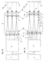
- a light source 1 and optical means 2 are shown.
- the light source 1 may be a suitable laser such as a laser diode bar or an excimer laser or a Nd: YAG laser.
- the optical means 2 may comprise collimating means and homogenizing means not shown in detail in order to collimate and homogenize the light 3 emanating from the light source 1.
- the device further comprises separating means 4, which can divide the light 3 into individual beams 5 a, 5 b which are separated from one another.
- the separating means comprise a first array 6 of first cylindrical lenses 7 and a second array 8 of second cylindrical lenses 9, both of which influence the light with respect to the X direction (see Fig. 1a ).
- the cylinder axes of the first and second lenses 7, 9 are aligned in the Y direction.
- Both the first array 6 and the second array 8 are each arranged on the entrance surface of a separate substrate.
- the apertures of all the first lenses 7 at least in the X direction are the same. Furthermore, the apertures of all second lenses 9 are the same, at least in the X direction.
- all of the first lenses 7 as well as all of the second lenses 9 are aligned symmetrically with respect to the mean propagation direction Z of the light 3, which is the mean propagation direction Z of the light 3 when passing through the first and / or the second lenses 7, 9 no distractions.
- one of the first lenses 7 is arranged in the Z direction exactly opposite one of the second lenses 9, so that their optical axes coincide.
- All first lenses 7 have the same focal length f 7 . Furthermore, all second lenses 9 have the same focal length f 9 .
- the distance of the first array 6 to the second Array 8 corresponds to the sum f 7 + f 9 of the focal lengths f 7 , f 9 of the first and second lenses 7, 9 (see Fig. 1b ).
- the first and second arrays 6, 8 thus form a telescope arrangement.
- the focal lengths f 7 of the first lenses 7 are larger, for example, about three times as large as the focal lengths f 9 of the second lenses 9. Therefore, the homogeneous light 3 by the consisting of the first array 6 and the second array 8 telescope with respect to the X Direction split into mutually separated sub-beams 5.
- the separating means further comprise a third array 10 of third cylindrical lenses 11 and a fourth array 12 of fourth cylindrical lenses 13, both of which influence the light with respect to the Y direction (see Fig. 1b ).
- the cylinder axes of the third and fourth lenses 11, 13 are aligned in the X direction.
- Both the third array 10 and the fourth array 12 are each disposed on the entrance surface of a separate substrate.
- the third array 10 is disposed between the first array 6 and the second array 8. Alternatively, it may also be arranged in the propagation direction of the light 3 in front of the first array 6 or behind the second array 8.
- the fourth array 12 is arranged behind the second array 8 in the illustrated embodiment in the propagation direction of the light 3. Alternatively, it may also be arranged between the first array 6 and the second array 8.
- the apertures of all third lenses 11 at least in the Y direction are the same. Furthermore, the apertures of all fourth lenses 13 are the same, at least in the Y direction. In addition, all of the third lenses 11, as well as all of the fourth lenses 13 are so symmetrical to the mean propagation direction Z of Light 3 aligned that the mean propagation direction Z of the light 3 in the passage through the third and / or the fourth lenses 11, 13 undergoes no deflection. Furthermore, in each case one of the third lenses 11 is arranged in the Z-direction exactly opposite one of the fourth lenses 13, so that their optical axes coincide.
- All third lenses 11 have the same focal length f 11 . Furthermore, all fourth lenses 13 have the same focal length f 13 .
- the distance of the third array 10 to the fourth array 12 corresponds to the sum f 11 + f 13 of the focal lengths f 11 , f 13 of the third and fourth lenses 11, 13 (see FIG Fig. 1b ).
- the third and fourth arrays 10, 12 thus likewise form a telescope arrangement.
- the focal lengths f 11 of the third lenses 11 are larger, for example about three times as large as the focal lengths f 13 of the fourth lenses 13. Therefore, the homogeneous light 3 is formed by the telescope consisting of the third array 10 and the fourth array 12 with respect to the Y Direction split into mutually separated sub-beams 5.
- the focal lengths f 7 of the first lenses 7 correspond to the focal lengths f 11 of the third lenses 11.
- the focal lengths f 9 of the second lenses 9 may correspond to the focal lengths f 13 of the fourth lenses 13.
- Illustrated arrays 6, 8, 10, 12 are shown only by way of example and may have a significantly larger number of lenses 7, 9, 11, 13.
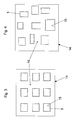
- the partial beams 5 emerging from the separating means 4 strike a mask 14 which has a plurality of openings 15 or transparent sections for the passage of the light.
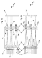
- Fig. 2a and Fig. 2b illustrated embodiment also comprises separating means 4 ', the four arrays 6', 8 ', 10', 12 'of lenses 7a, 7b, 7c; 9a, 9b, 9c; 11 a, 11 b, 11 c; 13a, 13b, 13c.
- the lenses 7a, 7b, 7c; 9a, 9b, 9c; 11a, 11b, 11c; 13a, 13b, 13c are also formed as cylindrical lenses and have one of the device according to Fig. 1a and Fig. 1b appropriate orientation.
- the focal lengths of the lenses 7a, 7b, 7c correspond; 9a, 9b, 9c; 11 a, 11 b, 11 c; 13a, 13b, 13c those of the lenses 7, 9, 11, 13 of the device according to Fig. 1a and Fig. 1b ,
- the lenses 7a, 7b, 7c; 9a, 9b, 9c; 11a, 11b, 11c; 13a, 13b, 13c do not all have the same aperture. Rather, the apertures of the first lenses 7a, 7b, 7c, at least in the X direction are not equal to each other. Furthermore, the apertures of the second lenses 9a, 9b, 9c are unequal to each other at least in the X direction. Furthermore, the apertures of the third lenses 11a, 11b, 11c are unequal to each other at least in the Y direction. Furthermore, the apertures of the fourth lenses 13a, 13b, 13c are unequal at least in the Y direction to each other. This results in different sized cross sections and / or different intensities of the partial beams 5 on the mask 14th
- any desired, in particular non-overlapping spot arrangements on the mask 14 can be achieved with the separating means 4 '.
- Fig. 5a and Fig. 5b are the same or functionally identical parts with the same reference numerals as in Fig. 1a, Fig. 1b .
- Fig. 2a and Fig. 2b are the same or functionally identical parts with the same reference numerals as in Fig. 1a, Fig. 1b .
- Fig. 2a and Fig. 2b are the same or functionally identical parts with the same reference numerals as in Fig. 1a, Fig. 1b .
- Fig. 2a and Fig. 2b are the same or functionally identical parts with the same reference numerals as in Fig. 1a, Fig. 1b .
- the illustrated embodiment of the separating means 4 "differs from the embodiment according to FIG Fig. 1a and Fig. 1b in that the first two arrays 6 "and 10" are combined on a substrate. Furthermore, the third array is divided into two spaced-apart sub-arrays 8a "and 8b". The second subarray 8b "is combined with the fourth array 12" on a substrate.
Landscapes
- Physics & Mathematics (AREA)
- General Physics & Mathematics (AREA)
- Optics & Photonics (AREA)
- Microscoopes, Condenser (AREA)
- Exposure And Positioning Against Photoresist Photosensitive Materials (AREA)
- Exposure Of Semiconductors, Excluding Electron Or Ion Beam Exposure (AREA)
- Non-Portable Lighting Devices Or Systems Thereof (AREA)
Applications Claiming Priority (2)
| Application Number | Priority Date | Filing Date | Title |
|---|---|---|---|
| DE200710062564 DE102007062564A1 (de) | 2007-12-22 | 2007-12-22 | Vorrichtung zur Ausleuchtung einer Fläche |
| DE102008012047 | 2008-03-01 |
Publications (2)
| Publication Number | Publication Date |
|---|---|
| EP2073061A2 true EP2073061A2 (fr) | 2009-06-24 |
| EP2073061A3 EP2073061A3 (fr) | 2011-02-23 |
Family
ID=40532485
Family Applications (1)
| Application Number | Title | Priority Date | Filing Date |
|---|---|---|---|
| EP08021427A Withdrawn EP2073061A3 (fr) | 2007-12-22 | 2008-12-10 | Dispositif destiné à l'éclairage d'une surface et dispositif d'application de lumière sur une zone de travail |
Country Status (4)
| Country | Link |
|---|---|
| US (1) | US8081386B2 (fr) |
| EP (1) | EP2073061A3 (fr) |
| JP (1) | JP2009151313A (fr) |
| KR (1) | KR20090068185A (fr) |
Cited By (3)
| Publication number | Priority date | Publication date | Assignee | Title |
|---|---|---|---|---|
| WO2011006710A3 (fr) * | 2009-07-14 | 2011-06-16 | Carl Zeiss Smt Gmbh | Condenseur alvéolaire notamment destiné à un dispositif d'éclairage par projection microlithographique |
| CN103412465A (zh) * | 2013-07-01 | 2013-11-27 | 中国科学院上海光学精密机械研究所 | 步进扫描投影光刻机的照明系统 |
| US10012907B2 (en) | 2014-06-06 | 2018-07-03 | Carl Zeiss Smt Gmbh | Optical system of a microlithographic projection exposure apparatus |
Families Citing this family (4)
| Publication number | Priority date | Publication date | Assignee | Title |
|---|---|---|---|---|
| DE102008027231B4 (de) * | 2008-06-06 | 2016-03-03 | Limo Patentverwaltung Gmbh & Co. Kg | Vorrichtung zur Strahlformung |
| US20130265780A1 (en) | 2012-04-05 | 2013-10-10 | Black & Decker Inc. | Light module and light stand assembly |
| US9354379B2 (en) * | 2014-09-29 | 2016-05-31 | Palo Alto Research Center Incorporated | Light guide based optical system for laser line generator |
| KR102750969B1 (ko) * | 2023-12-20 | 2025-01-09 | (주) 오로스테크놀로지 | 자동 초점 장치, 이를 구비한 오버레이 측정장치 및 자동 초점 장치의 교정 방법 |
Family Cites Families (15)
| Publication number | Priority date | Publication date | Assignee | Title |
|---|---|---|---|---|
| US5745153A (en) * | 1992-12-07 | 1998-04-28 | Eastman Kodak Company | Optical means for using diode laser arrays in laser multibeam printers and recorders |
| US5581408A (en) * | 1994-05-13 | 1996-12-03 | United Technologies Corporation | Method and apparatus for deflecting an optical beam |
| US5674414A (en) | 1994-11-11 | 1997-10-07 | Carl-Zeiss Stiftung | Method and apparatus of irradiating a surface of a workpiece with a plurality of beams |
| US5973844A (en) * | 1996-01-26 | 1999-10-26 | Proxemics | Lenslet array systems and methods |
| US6124974A (en) * | 1996-01-26 | 2000-09-26 | Proxemics | Lenslet array systems and methods |
| US6381072B1 (en) * | 1998-01-23 | 2002-04-30 | Proxemics | Lenslet array systems and methods |
| US7006295B2 (en) * | 2001-10-18 | 2006-02-28 | Asml Holding N.V. | Illumination system and method for efficiently illuminating a pattern generator |
| JP4096565B2 (ja) * | 2002-01-28 | 2008-06-04 | 富士ゼロックス株式会社 | マイクロレンズアレーの製造方法、それに用いる電解液および製造装置 |
| EP1380885A1 (fr) * | 2002-07-11 | 2004-01-14 | Agfa-Gevaert AG | Dispositif et procédé pour imprimer des images numériques sur matériaux photosensibles |
| US7139064B2 (en) * | 2003-06-23 | 2006-11-21 | Samsung Electronics Co., Ltd. | Optical system for providing a hexapole illumination and method of forming a photoresist pattern on a substrate using the same |
| KR100697837B1 (ko) * | 2003-09-18 | 2007-03-20 | 가부시끼가이샤 도시바 | 3차원 화상표시장치 |
| US7116404B2 (en) * | 2004-06-30 | 2006-10-03 | Asml Netherlands B.V | Lithographic apparatus and device manufacturing method |
| US7251020B2 (en) * | 2004-07-30 | 2007-07-31 | Asml Netherlands B.V. | Lithographic apparatus and device manufacturing method |
| JP4171479B2 (ja) * | 2005-06-28 | 2008-10-22 | 株式会社日立ハイテクノロジーズ | 荷電粒子線応用装置及び荷電粒子線応用方法 |
| JP5068271B2 (ja) * | 2006-02-17 | 2012-11-07 | カール・ツァイス・エスエムティー・ゲーエムベーハー | マイクロリソグラフィ照明システム、及びこの種の照明システムを含む投影露光装置 |
-
2008
- 2008-12-10 EP EP08021427A patent/EP2073061A3/fr not_active Withdrawn
- 2008-12-20 KR KR1020080130742A patent/KR20090068185A/ko not_active Ceased
- 2008-12-22 JP JP2008326603A patent/JP2009151313A/ja active Pending
- 2008-12-22 US US12/340,906 patent/US8081386B2/en active Active
Cited By (4)
| Publication number | Priority date | Publication date | Assignee | Title |
|---|---|---|---|---|
| WO2011006710A3 (fr) * | 2009-07-14 | 2011-06-16 | Carl Zeiss Smt Gmbh | Condenseur alvéolaire notamment destiné à un dispositif d'éclairage par projection microlithographique |
| CN103412465A (zh) * | 2013-07-01 | 2013-11-27 | 中国科学院上海光学精密机械研究所 | 步进扫描投影光刻机的照明系统 |
| CN103412465B (zh) * | 2013-07-01 | 2015-04-15 | 中国科学院上海光学精密机械研究所 | 步进扫描投影光刻机的照明系统 |
| US10012907B2 (en) | 2014-06-06 | 2018-07-03 | Carl Zeiss Smt Gmbh | Optical system of a microlithographic projection exposure apparatus |
Also Published As
| Publication number | Publication date |
|---|---|
| EP2073061A3 (fr) | 2011-02-23 |
| US20090161224A1 (en) | 2009-06-25 |
| US8081386B2 (en) | 2011-12-20 |
| JP2009151313A (ja) | 2009-07-09 |
| KR20090068185A (ko) | 2009-06-25 |
Similar Documents
| Publication | Publication Date | Title |
|---|---|---|
| EP1528425B1 (fr) | Assemblage et appareillage pour la transformation de faisceaux optiques | |
| DE10327733B3 (de) | Vorrichtung zur Formung eines Lichtstrahls | |
| DE19520187C1 (de) | Optik zum Herstellen einer scharfen Beleuchtungslinie aus einem Laserstrahl | |
| DE502007012156C5 (de) | Vorrichtung zur strahlformung | |
| DE112012000019B4 (de) | Glasfaserübertragung verwendendes Laseroptiksystem | |
| EP2430491B1 (fr) | Dispositif pour la mise en forme de rayonnement laser et dispositif laser correspondant | |
| EP2073061A2 (fr) | Dispositif destiné à l'éclairage d'une surface et dispositif d'application de lumière sur une zone de travail | |
| DE102007057868A1 (de) | Vorrichtung zur Strahlformung | |
| DE102020114077B4 (de) | Vorrichtung zur Homogenisierung von Laserlicht und Anordnung einer Mehrzahl derartiger Vorrichtungen | |
| EP1839083B1 (fr) | Dispositif d'homogeneisation de la lumiere | |
| DE102004034253A1 (de) | Vorrichtung für die Beleuchtung einer Fläche | |
| WO2005085934A1 (fr) | Dispositif pour generer une zone de focalisation lineaire pour une source de lumiere laser | |
| EP2054751A1 (fr) | Dispositif d'homogeneisation de lumiere et dispositif laser de production d'une repartition d'intensite lineaire dans un plan de travail | |
| WO2005085935A1 (fr) | Dispositif pour homogeneiser la lumiere, et systeme d'eclairage ou de focalisation faisant appel a ce dispositif | |
| DE102007026730A1 (de) | Vorrichtung zur Erzeugung einer homogenen Winkelverteilung einer Laserstrahlung | |
| DE69602952T2 (de) | Optische faservorrichtung zur optischen verarbeitung eines laserstrahls | |
| DE102011076658A1 (de) | Beleuchtungsoptik für die EUV-Projektionslithographie | |
| EP2976672B1 (fr) | Dispositif d'homogénéisation d'un rayon laser | |
| EP4041479A1 (fr) | Dispositif laser pour générer un rayonnement laser et dispositif d'impression 3d comprenant un tel dispositif laser | |
| DE102007062564A1 (de) | Vorrichtung zur Ausleuchtung einer Fläche | |
| DE102020130651B3 (de) | Vorrichtung zum Erzeugen einer definierten Laserbeleuchtung auf einer Arbeitsebene | |
| WO2022248209A1 (fr) | Dispositif pour produire un éclairage laser défini sur un plan de travail | |
| DE102006009212A1 (de) | Optische Vorrichtung und optisches Verfahren zur Homogenisierung von Laserstrahlung | |
| DE102021130604B3 (de) | Vorrichtung zur Formung einer Laserstrahlung und Laservorrichtung | |
| WO2003005104A2 (fr) | Systeme pour representer la lumiere provenant d'une barrette de diodes laser dans un plan focal |
Legal Events
| Date | Code | Title | Description |
|---|---|---|---|
| PUAI | Public reference made under article 153(3) epc to a published international application that has entered the european phase |
Free format text: ORIGINAL CODE: 0009012 |
|
| AK | Designated contracting states |
Kind code of ref document: A2 Designated state(s): AT BE BG CH CY CZ DE DK EE ES FI FR GB GR HR HU IE IS IT LI LT LU LV MC MT NL NO PL PT RO SE SI SK TR |
|
| AX | Request for extension of the european patent |
Extension state: AL BA MK RS |
|
| PUAL | Search report despatched |
Free format text: ORIGINAL CODE: 0009013 |
|
| AK | Designated contracting states |
Kind code of ref document: A3 Designated state(s): AT BE BG CH CY CZ DE DK EE ES FI FR GB GR HR HU IE IS IT LI LT LU LV MC MT NL NO PL PT RO SE SI SK TR |
|
| AX | Request for extension of the european patent |
Extension state: AL BA MK RS |
|
| 17P | Request for examination filed |
Effective date: 20110823 |
|
| AKX | Designation fees paid |
Designated state(s): AT BE BG CH CY CZ DE DK EE ES FI FR GB GR HR HU IE IS IT LI LT LU LV MC MT NL NO PL PT RO SE SI SK TR |
|
| STAA | Information on the status of an ep patent application or granted ep patent |
Free format text: STATUS: THE APPLICATION IS DEEMED TO BE WITHDRAWN |
|
| 18D | Application deemed to be withdrawn |
Effective date: 20110824 |