EP2073070A2 - Four à vapeur à commande de pression pour le contrôle de température asymptotique de support d'alimentation continue - Google Patents
Four à vapeur à commande de pression pour le contrôle de température asymptotique de support d'alimentation continue Download PDFInfo
- Publication number
- EP2073070A2 EP2073070A2 EP08171720A EP08171720A EP2073070A2 EP 2073070 A2 EP2073070 A2 EP 2073070A2 EP 08171720 A EP08171720 A EP 08171720A EP 08171720 A EP08171720 A EP 08171720A EP 2073070 A2 EP2073070 A2 EP 2073070A2
- Authority
- EP
- European Patent Office
- Prior art keywords
- pressure
- pressure chamber
- vapor
- temperature
- chamber
- Prior art date
- Legal status (The legal status is an assumption and is not a legal conclusion. Google has not performed a legal analysis and makes no representation as to the accuracy of the status listed.)
- Withdrawn
Links
Images


Classifications
-
- G—PHYSICS
- G03—PHOTOGRAPHY; CINEMATOGRAPHY; ANALOGOUS TECHNIQUES USING WAVES OTHER THAN OPTICAL WAVES; ELECTROGRAPHY; HOLOGRAPHY
- G03G—ELECTROGRAPHY; ELECTROPHOTOGRAPHY; MAGNETOGRAPHY
- G03G15/00—Apparatus for electrographic processes using a charge pattern
- G03G15/20—Apparatus for electrographic processes using a charge pattern for fixing, e.g. by using heat
- G03G15/2003—Apparatus for electrographic processes using a charge pattern for fixing, e.g. by using heat using heat
-
- H—ELECTRICITY
- H05—ELECTRIC TECHNIQUES NOT OTHERWISE PROVIDED FOR
- H05K—PRINTED CIRCUITS; CASINGS OR CONSTRUCTIONAL DETAILS OF ELECTRIC APPARATUS; MANUFACTURE OF ASSEMBLAGES OF ELECTRICAL COMPONENTS
- H05K3/00—Apparatus or processes for manufacturing printed circuits
- H05K3/30—Assembling printed circuits with electric components, e.g. with resistors
- H05K3/32—Assembling printed circuits with electric components, e.g. with resistors electrically connecting electric components or wires to printed circuits
-
- H—ELECTRICITY
- H05—ELECTRIC TECHNIQUES NOT OTHERWISE PROVIDED FOR
- H05K—PRINTED CIRCUITS; CASINGS OR CONSTRUCTIONAL DETAILS OF ELECTRIC APPARATUS; MANUFACTURE OF ASSEMBLAGES OF ELECTRICAL COMPONENTS
- H05K1/00—Printed circuits
- H05K1/18—Printed circuits structurally associated with non-printed electric components
- H05K1/189—Printed circuits structurally associated with non-printed electric components characterised by the use of flexible or folded printed circuits
-
- H—ELECTRICITY
- H05—ELECTRIC TECHNIQUES NOT OTHERWISE PROVIDED FOR
- H05K—PRINTED CIRCUITS; CASINGS OR CONSTRUCTIONAL DETAILS OF ELECTRIC APPARATUS; MANUFACTURE OF ASSEMBLAGES OF ELECTRICAL COMPONENTS
- H05K2203/00—Indexing scheme relating to apparatus or processes for manufacturing printed circuits covered by H05K3/00
- H05K2203/07—Treatments involving liquids, e.g. plating, rinsing
- H05K2203/0736—Methods for applying liquids, e.g. spraying
- H05K2203/074—Features related to the fluid pressure
-
- H—ELECTRICITY
- H05—ELECTRIC TECHNIQUES NOT OTHERWISE PROVIDED FOR
- H05K—PRINTED CIRCUITS; CASINGS OR CONSTRUCTIONAL DETAILS OF ELECTRIC APPARATUS; MANUFACTURE OF ASSEMBLAGES OF ELECTRICAL COMPONENTS
- H05K2203/00—Indexing scheme relating to apparatus or processes for manufacturing printed circuits covered by H05K3/00
- H05K2203/11—Treatments characterised by their effect, e.g. heating, cooling, roughening
- H05K2203/1105—Heating or thermal processing not related to soldering, firing, curing or laminating, e.g. for shaping the substrate or during finish plating
Definitions
- This invention relates to steam-based manufacturing systems, and in particular to steam fusers for xerographic systems.
- xerographic or electrostatographic printers In xerographic or electrostatographic printers (collectively referred to herein as "xerographic systems"), a charge-retentive member is charged to a uniform potential and thereafter exposed to a light image of an original document to be reproduced. The exposure discharges the charge-retentive surface in exposed or background areas and creates an electrostatic latent image on the member which corresponds to the image areas contained within the original document. Subsequently, the electrostatic latent image on the charge-retentive surface is rendered visible by developing the image with developing powder.
- Many development systems employ a developer material which comprises both charged carrier particles and charged toner particles which triboelectrically adhere to the carrier particles.
- the toner particles are attracted from the carrier particles by the charge pattern of the image areas on the charge-retentive area to form a powder image on the charge-retentive area.
- This image is subsequently transferred to a substrate (e.g., a sheet of paper), which is then transferred through a fuser to permanently affix the toner to the substrate by applying heat and/or pressure that causes the temperature of the toner material to be elevated to a temperature at which the toner material coalesces and becomes tacky. This heating causes the toner to flow to some extent into the fibers or pores of the substrate.
- solidification of the toner material causes the toner material to become bonded to the substrate.
- Xerographic systems utilize either contact type fusers, such as the pressure fuser mentioned above, or contactless systems such as flash, radiant or steam fusers to fix toner material to a substrate.
- the substrate is pressed between two rollers, at least one of which is heated to a temperature high enough to cause the toner to bind to the substrate.
- contacting methods are problematic because they result in poor heat coupling to the media due to media roughness and a trapped air layer between the media and the heat transfer surface.
- Steam fusers utilize a steam oven to rapidly heat the substrate to the desired temperature in order to affix the toner.
- the cool substrate leaves the toner transfer apparatus and is directed into a steam oven containing steam at a temperature of approximately 180°C ⁇ 10°C).
- the substrate is thus heated by steam condensation and concomitant release of latent heat, as well as by convective heat transfer to the desired temperature.
- heating of the substrate is predominantly achieved through steam condensation heat transfer, which usually occurs in a time of order of 100 milliseconds (ms), independent of steam temperature.
- a condensate liquid layer approximately 4 microns thick results during this condensation heating process that must be re-evaporated and before the substrate can be heated above the boiling point (e.g., 100 °C).
- Re-evaporation of the condensate liquid layer takes about one second, during which this liquid layer can be rapidly imbibed by capillary infusion into the fiber matrix of the substrate (if uncoated).
- the fibers are able to move and relax non-uniform stresses (built into the paper during manufacture by cooling and quenching-in the non-uniform stresses under pressure and hygro-expansivity). This is called cockling and is undesirable. Once the cockling appears, subsequent drying of the unconstrained paper is not effective in reversing the distortion.
- the present invention is directed to a non-atmospheric pressure steam (or other vapor) oven system and method that utilize a controllable pressure zone to facilitate fast phase change heat transfer at any desired temperature to heat or cool target objects (e.g., flat substrates, such as sheets of paper), and also to the use of this system/method for leveling of temperatures across different locations of the objects.
- the system/method enables the use of a heat transfer fluid, such as water, without being limited to a particular temperature, such as the fluid's natural boiling point at atmospheric pressure.
- the invention also enables the use of fast phase change heat transfer processes for heating/cooling various thin substrates (e.g., in printing applications for paper/plastics/packaging materials or in other manufacturing applications with thin substrates which require fast efficient heat transfer) without being limited to the natural boiling point temperature of the heat transfer fluid at standard atmospheric pressure.
- the system/method may be utilized in other manufacturing applications as well.
- the steam oven system includes a steam oven (hermetic enclosure) defining a pressure chamber having sealed entry and exit ports for transferring a web or substrate (i.e., an object such as a sheet of paper) with added material (e.g., a markant such as toner, wax, components to be glued, etc.) through the pressure chamber, and a temperature/pressure regulation apparatus for setting the saturation temperature (boiling point) of heat transfer fluid inside the steam oven to an optimal heating/cooling temperature by selectively controlling the pressure inside the hermetic enclosure. For example, by reducing the pressure from one standard atmosphere to 0.2 bars absolute (-12 psig or 3 psia), the boiling temperature of water is reduced from 100°C to 60°C.
- the saturated steam temperature at equilibrium under these conditions is also 60°C, and the phase change between liquid and vapor, with its concomitant exchange of latent heat, occurs at 60°C.
- the boiling point can be increased to 120°C by raising the system pressure to 1 atmospheres (15 psig).
- Objects such as a sheet of paper in this environment would tend toward an equilibrium in a self-limiting way at the selected boiling point--those objects at temperatures higher than the saturation temperature would tend to evaporatively cool by losing any native moisture (e.g., a sheet of paper entering the system with typical 6 to 8% moisture content), and those with temperatures lower than the saturation temperature would tend to heat up due to condensation heat transfer from the surrounding steam.
- a substrate can be rapidly heated by condensation to temperatures well above 100°C.
- the boiling point can be set to 120°C, say, and the substrate dwell time in the steam environment set to achieve heating to 110°C.
- the heating rate is much faster below the asymptotic temperature than close to the boiling temperature.
- the steam oven system is disposed downstream from a toner transfer device in a xerographic system, water is used as the heat transfer fluid and is stored in a reservoir within, or in direct communication with, the pressure chamber.
- the heat transfer fluid is heated by a heater to a controlled set point temperature.
- the pressure chamber equilibrates to the vapor pressure of the heat transfer fluid at the set temperature.
- Optimal conditions are generated such that an internal pressure of the pressure chamber is different from (i.e., above or below) an atmospheric pressure external to the pressure chamber, and such that a temperature inside the pressure chamber is equal to or greater than the boiling point temperature of the heat transfer fluid at the internal pressure.
- the substrate, with un-fused toner material disposed thereon, is then transferred through the pressure chamber by way of the sealed entry and exit portions (i.e., such that no significant change occurs in the pressure differential between the internal pressure of the pressure chamber and the external atmospheric pressure), thereby heating the substrate to the internal temperature and fusing the toner material to the substrate.
- This arrangement facilitates the production of xerographic systems in which the peak temperature of the fusing process may be substantially lower (or higher) than the standard boiling temperature of water at atmospheric pressure (i.e., 100°C).
- the sealed entry and exit ports include compliant roller nips that serve to transport a substrate (e.g., a sheet of paper) through the pressure chamber. Heated walls largely enclose the roller nips so that condensation is minimized on the rollers in the region outside the chamber.
- multiple walls that open and close are used (e.g., two parallel walls on the substrate input and output sides) that act as a 'load lock' to provide a transition region for entry and exit without loss of pressure in the internal pressure chamber.
- a differentially pumped outer chamber is provided in lieu of nip sealing. Air entering or vapor leaving the pressure chamber are exhausted (and optionally recycled) by pumping the outer chamber to a pressure lower than both the atmospheric and pressure chamber pressures.
- Fig. 1 is a simplified side view showing a non-atmospheric pressure steam oven system according to an embodiment of the present invention
- Figs. 2(A) and 2(B) are graphs showing changes in the vapor pressure of water at various combinations of temperature and pressure.
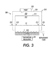
- Fig. 3 is a simplified side view showing a non-atmospheric pressure steam oven system according to another embodiment of the present invention.
- the present invention relates to an improvement in steam fuser apparatus for xerographic systems.
- the following description is presented to enable one of ordinary skill in the art to make and use the invention as provided in the context of a particular application and its requirements.
- Various modifications to the preferred embodiment will be apparent to those with skill in the art, and the general principles defined herein may be applied to other embodiments. Therefore, the present invention is not intended to be limited to the particular embodiments shown and described, but is to be accorded the widest scope consistent with the principles and novel features herein disclosed.
- vapor is the condensable gas phase component of a liquid that is in actual or virtual contact with its liquid phase, and is distinguished from the pure gas phase by the presence of the liquid phase.
- steam is used as an example of (water) vapor that is formed over and in contact with a pool of liquid water.
- a non-atmospheric pressure steam oven system may utilize a non-water heat transfer fluid in which the generated vapor does not comprise steam.
- Fig. 1 is a simplified side view showing a portion of a xerographic system 50 including a non-atmospheric pressure steam oven system 100 according to an exemplary embodiment of the present invention.
- Steam oven system 100 is positioned immediately downstream of a toner transfer device 60 that utilizes two rotating drums 61 and 62 to transfer toner onto a substrate 55 in a predetermined pattern according to known xerographic techniques.
- Steam oven system 100 generally includes a steam oven (hermetic enclosure) 110 defining a controllable pressure chamber 111, and a pressure regulation apparatus 130.
- steam oven system 100 utilizes water-based steam to heat substrate 55 to a predetermined optimal temperature, and to maintain substrate 55 at or above the predetermined temperature for a predetermined time period in order to facilitate melting of the toner and fusing of the toner to substrate 55.
- steam oven system 100 controls the pressure in pressure chamber 111 in a way that generates steam at temperatures other than those normally associated with the boiling point of water under atmospheric conditions (i.e., 100°C). In this way, steam oven system 100 facilitates fast phase change heat transfer at a predetermined temperature to heat (or in other applications, to cool) substrate 55, and also to level the temperatures across different locations of substrate 55, thus optimizing the fusing process for a selected toner.
- Steam oven 110 is constructed using conventional materials and manufacturing techniques such that pressure chamber 111 is airtight and sufficiently strong to withstand a pressure differential between pressure chamber 111 and external atmospheric conditions. Steam oven 110 is accessible by way of a sealed entry port 113 and a sealed exit port 115.
- sealed entry port 113 includes compliant roller nips (wheels) 121 and 123
- sealed exit port 115 includes compliant rollers nips 125 and 127 constructed using conventional materials and manufacturing techniques that serve to transport substrate 55 through pressure chamber 111 without significant loss of pressure.
- the external walls of steam oven 110 are heated to a temperature slightly above steam temperature, and secondary heated wall portions 117 and 119 enclose roller nips 121/123 and 125/127 to avoid condensation on nips.
- temperature/pressure regulation apparatus 130 includes a temperature regulator 131 that controls the temperature of liquid heat transfer fluid L, which is disposed in pressure chamber 111, by way of an immersed resistive heater 132 to a controlled set point.
- chamber 111 equilibrates to the vapor pressure of heat transfer fluid L at the set temperature.
- An optional pressure regulation device (e.g., a pump) 135 further controls the pressure inside chamber 111 by way of pipe 136.
- Optimal conditions are generated by temperature/pressure regulation apparatus 130 such that an internal pressure of camber 111 is different from (i.e., above or below) an atmospheric pressure external to the pressure chamber, and such that a temperature inside the pressure chamber is equal to or greater than the boiling point temperature of the heat transfer fluid at the internal pressure.
- Objects, such as substrate 55 (i.e., a sheet of paper) disposed in pressure chamber 111 would tend toward an equilibrium in a self-limiting way at the selected boiling point--those objects at temperatures higher than the saturation temperature (e.g., higher than 60°C) would tend to evaporatively cool by losing any native moisture, and those with temperatures lower than the saturation temperature (e.g., higher than 60°C) would tend to heat up due to condensation heat transfer from the surrounding steam.
- the present invention enables efficient heating of substrate 55 to the desired temperature, and also in leveling of any temperature non-uniformities in substrate 55 during the fusing process, thereby facilitating a fusing process at a much lower temperature than under atmospheric conditions
- the boiling point can be increased to 120°C by heating the heat transfer fluid (water) thereby raising the system pressure to 1 atmospheres (15 psig).
- Figs. 2(A) and 2(B) show various vapor pressures for water under different pressure and temperature conditions.
- An important point of the invention is that the transported sheet will approach equilibrium at or near the boiling point of water at the set pressure in a self-limiting manner. If the sheet enters at a higher temperature, it will dry and cool; if at a lower temperature, it will moisten and heat.
- a second important aspect of the invention is that rapid condensation heating of substrates can work above 100°C by having the boiling point be greater than the target substrate temperature.
- a hot substrate can be wetted with a surface layer of water before entry to steam oven 110 (e.g., by spraying with water, or passing the substrate through a cool humid environment before entering the hermetic enclosure). In that case the sheet can be cooled without depending on the presence of any native moisture in the bulk of the paper.
- Fig. 3 is a simplified side view showing a non-atmospheric pressure steam oven system 200 according to another embodiment of the present invention.
- Steam oven 210 is constructed using conventional materials and includes an inner wall 211 defining an inner (pressure) chamber 212 and an outer wall 221 defining an outer chamber 222.
- Inner chamber 212 is accessed by way of an entry port 213 and an exit port 215.
- Outer chamber 222 is accessed by way of an entry port 223 and an exit port 225 that are respectively aligned with entry/exit ports 213 and 215 so that substrate 55 passes through steam oven 210 along a straight path.
- Heat transfer fluid L is disposed in inner chamber 212 and is heated by, for example, an immersed resistive heater 232 to a set point temperature determined by a temperature regulator (controller) 231.
- Pressure chamber 212 equilibrates to the vapor pressure of heat transfer fluid L at the selected set point temperature.
- Optimal conditions are generated such that an internal pressure of pressure chamber 212 is different from (i.e., above or below) an atmospheric pressure external to steam oven 210, and such that a temperature inside pressure chamber 212 is equal to or greater than the boiling point temperature of heat transfer fluid L at the internal pressure.
- a pump 235 maintains outer chamber 222 at a pressure that is lower than both the atmospheric pressure located outside steam oven 210 and inner (pressure) chamber 212, thereby exhausting (and optionally recycling) both air entering outer chamber 222 from outside steam oven 210 through entry/exit ports 233 and 235, and steam (or other vapor) entering outer chamber 222 from inner chamber 212 through entry/exit ports 213 and 215.
- differentially pumped outer chamber 222 is provided in lieu of the nip sealing arrangement utilized in the embodiment of Fig. 1 (discussed above).
- the present invention may be utilized in the manufacture of a wide range of products utilizing thin substrates without being limited to the natural boiling point temperature of the heat transfer fluid (e.g., water) at standard atmospheric pressure.
- the present invention is described as including immersion-type heaters, other systems may be used to heat the heat transfer fluid disposed in or communicating with the vapor oven. Such other applications include self-limited surface heating of any thin objects transported by a web, and controlled melting of layers on a web without over-heating (e.g. thermo-plastic or thermosetting bonding of chips or other objects to flex PCBs).
Landscapes
- Engineering & Computer Science (AREA)
- Physics & Mathematics (AREA)
- General Physics & Mathematics (AREA)
- Manufacturing & Machinery (AREA)
- Microelectronics & Electronic Packaging (AREA)
- Fixing For Electrophotography (AREA)
- Paper (AREA)
Applications Claiming Priority (1)
| Application Number | Priority Date | Filing Date | Title |
|---|---|---|---|
| US11/959,406 US7890043B2 (en) | 2007-12-18 | 2007-12-18 | Pressure-controlled steam oven for asymptotic temperature control of continuous feed media |
Publications (2)
| Publication Number | Publication Date |
|---|---|
| EP2073070A2 true EP2073070A2 (fr) | 2009-06-24 |
| EP2073070A3 EP2073070A3 (fr) | 2012-06-27 |
Family
ID=40445500
Family Applications (1)
| Application Number | Title | Priority Date | Filing Date |
|---|---|---|---|
| EP08171720A Withdrawn EP2073070A3 (fr) | 2007-12-18 | 2008-12-16 | Four à vapeur à commande de pression pour le contrôle de température asymptotique de support d'alimentation continue |
Country Status (3)
| Country | Link |
|---|---|
| US (1) | US7890043B2 (fr) |
| EP (1) | EP2073070A3 (fr) |
| JP (1) | JP5313650B2 (fr) |
Families Citing this family (9)
| Publication number | Priority date | Publication date | Assignee | Title |
|---|---|---|---|---|
| US7801475B2 (en) * | 2007-12-18 | 2010-09-21 | Palo Alto Research Center Incorporated | Ultra-heated/slightly heated steam zones for optimal control of water content in steam fuser |
| US8606165B2 (en) * | 2008-04-30 | 2013-12-10 | Xerox Corporation | Extended zone low temperature non-contact heating for distortion free fusing of images on non-porous material |
| US20100038828A1 (en) * | 2008-08-18 | 2010-02-18 | Konal Engineering And Equipment, Inc. | Moulding method using microwaves |
| US8378263B2 (en) * | 2008-10-13 | 2013-02-19 | Palo Alto Research Center Incorporated | Hybrid multi-zone fusing |
| US9303316B1 (en) * | 2010-01-15 | 2016-04-05 | Apollo Precision Kunming Yuanhong Limited | Continuous web apparatus and method using an air to vacuum seal and accumulator |
| US8818252B2 (en) * | 2012-10-29 | 2014-08-26 | Eastman Kodak Company | Toner fixer transporting medium through heating liquid |
| DE102013201552B4 (de) * | 2013-01-30 | 2017-03-30 | Océ Printing Systems GmbH & Co. KG | Druckanordnung zum beidseitigen Bedrucken eines Aufzeichnungsträgers und Druckverfahren |
| DE102013201549B3 (de) | 2013-01-30 | 2014-06-18 | Océ Printing Systems GmbH & Co. KG | Druckanordnung zum beidseitigen Bedrucken eines Aufzeichnungsträgers und Druckverfahren |
| JP6167962B2 (ja) * | 2014-03-24 | 2017-07-26 | 富士ゼロックス株式会社 | 物理量推定装置、画像形成装置、及びプログラム |
Citations (4)
| Publication number | Priority date | Publication date | Assignee | Title |
|---|---|---|---|---|
| US3561130A (en) * | 1968-08-28 | 1971-02-09 | Continental Can Co | Method and apparatus for fixing deposited medium by vapor application |
| JPS5550289A (en) * | 1978-10-06 | 1980-04-11 | Ricoh Co Ltd | Developer vapor capturing device in electrophotography |
| JPS62160476A (ja) * | 1986-01-09 | 1987-07-16 | Ricoh Co Ltd | 溶剤定着装置 |
| US6067437A (en) * | 1997-12-15 | 2000-05-23 | Heidelberger Druckmaschinen Ag | Device for fixing toner images |
Family Cites Families (6)
| Publication number | Priority date | Publication date | Assignee | Title |
|---|---|---|---|---|
| GB859788A (en) * | 1958-06-30 | 1961-01-25 | Otto Kurt Kolb | Xerographic fixing apparatus |
| FR2499228B1 (fr) * | 1981-01-30 | 1985-10-25 | Carreras Michelle | Procede de chauffage d'objets a haute temperature par vapeur sous pression et appareil de mise en oeuvre |
| US5235903A (en) * | 1992-03-17 | 1993-08-17 | Tippmann Eugene R | Subatmospheric pressure cook-and-hold steaming oven |
| JP3397313B2 (ja) * | 1999-12-20 | 2003-04-14 | 富士通株式会社 | 半導体装置の製造方法及び電子部品の実装方法 |
| JP3378852B2 (ja) * | 1999-12-20 | 2003-02-17 | 富士通株式会社 | 加熱溶融処理装置 |
| US6334033B1 (en) * | 2000-05-01 | 2001-12-25 | Xerox Corporation | Ambient atmospheric pressure compensation controller for pressurized copying device |
-
2007
- 2007-12-18 US US11/959,406 patent/US7890043B2/en not_active Expired - Fee Related
-
2008
- 2008-12-15 JP JP2008318818A patent/JP5313650B2/ja not_active Expired - Fee Related
- 2008-12-16 EP EP08171720A patent/EP2073070A3/fr not_active Withdrawn
Patent Citations (4)
| Publication number | Priority date | Publication date | Assignee | Title |
|---|---|---|---|---|
| US3561130A (en) * | 1968-08-28 | 1971-02-09 | Continental Can Co | Method and apparatus for fixing deposited medium by vapor application |
| JPS5550289A (en) * | 1978-10-06 | 1980-04-11 | Ricoh Co Ltd | Developer vapor capturing device in electrophotography |
| JPS62160476A (ja) * | 1986-01-09 | 1987-07-16 | Ricoh Co Ltd | 溶剤定着装置 |
| US6067437A (en) * | 1997-12-15 | 2000-05-23 | Heidelberger Druckmaschinen Ag | Device for fixing toner images |
Also Published As
| Publication number | Publication date |
|---|---|
| EP2073070A3 (fr) | 2012-06-27 |
| US20090154969A1 (en) | 2009-06-18 |
| JP2009151304A (ja) | 2009-07-09 |
| JP5313650B2 (ja) | 2013-10-09 |
| US7890043B2 (en) | 2011-02-15 |
Similar Documents
| Publication | Publication Date | Title |
|---|---|---|
| US7890043B2 (en) | Pressure-controlled steam oven for asymptotic temperature control of continuous feed media | |
| US8265505B2 (en) | Selective cooling of a fuser heater roller | |
| US4197445A (en) | Roll fuser apparatus and system therefor | |
| US9081343B2 (en) | Image forming apparatus controlling for glossiness | |
| US8457515B2 (en) | Apparatus and method for controlling pressure roll flare in a print apparatus | |
| JP6274661B2 (ja) | 乾燥装置 | |
| US7801475B2 (en) | Ultra-heated/slightly heated steam zones for optimal control of water content in steam fuser | |
| US8143558B2 (en) | Apparatuses useful for printing and methods for controlling the temperature of media in apparatuses useful for printing | |
| JP2013024912A (ja) | 記録材冷却加湿装置、画像形成装置及び画像加熱システム | |
| WO2011024637A1 (fr) | Appareil et procédé de couchage à nappe | |
| US8378263B2 (en) | Hybrid multi-zone fusing | |
| US8929793B2 (en) | Recording substrate treatment apparatus and method | |
| US6979802B2 (en) | Apparatus and method for thermally processing an imaging material employing a preheat chamber | |
| US20110194868A1 (en) | Selective cooling of a fuser | |
| US8837970B2 (en) | Apparatus, methods, and systems for engaging and disengaging a fixing nip for cut sheet processing | |
| US20220324240A1 (en) | Image forming apparatus | |
| JP2020112662A (ja) | 液体付与装置及び画像形成装置 | |
| JP3168446U (ja) | 感熱製品のために紙/厚紙ウェブのカーリングを制御するための方法及び組立体 | |
| JP4048361B2 (ja) | 印刷装置のオーブン定着装置 | |
| JP3920790B2 (ja) | 乾燥装置及び乾燥方法 | |
| JP2003228254A (ja) | オーブン定着装置 | |
| JP2012226126A5 (ja) | 画像形成装置、及び画像形成方法 | |
| JPH08305206A (ja) | 定着装置 | |
| JP2019045560A (ja) | 加熱装置、画像形成装置及び加熱制御プログラム |
Legal Events
| Date | Code | Title | Description |
|---|---|---|---|
| PUAI | Public reference made under article 153(3) epc to a published international application that has entered the european phase |
Free format text: ORIGINAL CODE: 0009012 |
|
| AK | Designated contracting states |
Kind code of ref document: A2 Designated state(s): AT BE BG CH CY CZ DE DK EE ES FI FR GB GR HR HU IE IS IT LI LT LU LV MC MT NL NO PL PT RO SE SI SK TR |
|
| AX | Request for extension of the european patent |
Extension state: AL BA MK RS |
|
| RIC1 | Information provided on ipc code assigned before grant |
Ipc: G03G 15/20 20060101AFI20120413BHEP |
|
| PUAL | Search report despatched |
Free format text: ORIGINAL CODE: 0009013 |
|
| AK | Designated contracting states |
Kind code of ref document: A3 Designated state(s): AT BE BG CH CY CZ DE DK EE ES FI FR GB GR HR HU IE IS IT LI LT LU LV MC MT NL NO PL PT RO SE SI SK TR |
|
| AX | Request for extension of the european patent |
Extension state: AL BA MK RS |
|
| RIC1 | Information provided on ipc code assigned before grant |
Ipc: G03G 15/20 20060101AFI20120524BHEP |
|
| 17P | Request for examination filed |
Effective date: 20130102 |
|
| AKX | Designation fees paid |
Designated state(s): DE FR GB |
|
| 17Q | First examination report despatched |
Effective date: 20160314 |
|
| GRAP | Despatch of communication of intention to grant a patent |
Free format text: ORIGINAL CODE: EPIDOSNIGR1 |
|
| INTG | Intention to grant announced |
Effective date: 20180416 |
|
| STAA | Information on the status of an ep patent application or granted ep patent |
Free format text: STATUS: THE APPLICATION IS DEEMED TO BE WITHDRAWN |
|
| 18D | Application deemed to be withdrawn |
Effective date: 20180828 |