EP2073169A2 - Appareil de traitement d'image et procédé et programme - Google Patents
Appareil de traitement d'image et procédé et programme Download PDFInfo
- Publication number
- EP2073169A2 EP2073169A2 EP08254011A EP08254011A EP2073169A2 EP 2073169 A2 EP2073169 A2 EP 2073169A2 EP 08254011 A EP08254011 A EP 08254011A EP 08254011 A EP08254011 A EP 08254011A EP 2073169 A2 EP2073169 A2 EP 2073169A2
- Authority
- EP
- European Patent Office
- Prior art keywords
- edge
- image
- reference value
- edge point
- extraction
- Prior art date
- Legal status (The legal status is an assumption and is not a legal conclusion. Google has not performed a legal analysis and makes no representation as to the accuracy of the status listed.)
- Withdrawn
Links
Images


Classifications
-
- G—PHYSICS
- G06—COMPUTING OR CALCULATING; COUNTING
- G06T—IMAGE DATA PROCESSING OR GENERATION, IN GENERAL
- G06T7/00—Image analysis
- G06T7/0002—Inspection of images, e.g. flaw detection
-
- G—PHYSICS
- G06—COMPUTING OR CALCULATING; COUNTING
- G06T—IMAGE DATA PROCESSING OR GENERATION, IN GENERAL
- G06T7/00—Image analysis
- G06T7/10—Segmentation; Edge detection
- G06T7/13—Edge detection
-
- G—PHYSICS
- G06—COMPUTING OR CALCULATING; COUNTING
- G06V—IMAGE OR VIDEO RECOGNITION OR UNDERSTANDING
- G06V10/00—Arrangements for image or video recognition or understanding
- G06V10/40—Extraction of image or video features
- G06V10/44—Local feature extraction by analysis of parts of the pattern, e.g. by detecting edges, contours, loops, corners, strokes or intersections; Connectivity analysis, e.g. of connected components
- G06V10/443—Local feature extraction by analysis of parts of the pattern, e.g. by detecting edges, contours, loops, corners, strokes or intersections; Connectivity analysis, e.g. of connected components by matching or filtering
-
- G—PHYSICS
- G06—COMPUTING OR CALCULATING; COUNTING
- G06T—IMAGE DATA PROCESSING OR GENERATION, IN GENERAL
- G06T2207/00—Indexing scheme for image analysis or image enhancement
- G06T2207/20—Special algorithmic details
- G06T2207/20016—Hierarchical, coarse-to-fine, multiscale or multiresolution image processing; Pyramid transform
-
- G—PHYSICS
- G06—COMPUTING OR CALCULATING; COUNTING
- G06T—IMAGE DATA PROCESSING OR GENERATION, IN GENERAL
- G06T2207/00—Indexing scheme for image analysis or image enhancement
- G06T2207/20—Special algorithmic details
- G06T2207/20021—Dividing image into blocks, subimages or windows
Definitions
- the present invention contains subject matter related to Japanese Patent Application JP 2007-325511 filed in the Japanese Patent Office on December 18, 2007, the entire contents of which are incorporated herein by reference.
- the present invention relates to an image processing apparatus and method, and a program, and more specifically, the invention relates to an image processing apparatus and method for detecting a blur state of an image, and a program.
- edge point a pixel constituting an edge in an image
- type of the extracted edge point is analyzed, so that a blur degree which is an index indicating a blur state of the image is detected (for example, refer to Hanghang Tong, Mingjing Li, Hongjiang Zhang, Changshui Zhang, "Blur Detection for Digital Images Using Wavelet Transform", Multimedia and Expo, 2004. ICME '04. 2004 IEEE International Conference on, 27-30 June 2004, page(s) 17-20 ).
- the amount of the edge included in the image largely varies depending on a type of a subject such as scenery or a human face (hereinafter, also referred to as edge amount).
- edge amount is large in an image such as an artificial pattern or an architectural structure which includes much texture
- the edge amount is small in an image such as natural scenery or a human face which includes not much texture.
- the present invention has been made in view of the above-mentioned situation, and it is desirable to enable the detection for the blur state of the image at a higher accuracy.
- an image processing apparatus configured to extract an edge point which is a pixel constituting an edge in an image, perform an analysis as to whether or not a blur is generated in the extracted edge point, and detect a blur state of the image on the basis of the analysis result
- the image processing apparatus including: edge intensity detection means adapted to detect an intensity of the edge of the image in units of a block of a predetermined size; parameter adjustment means adapted to adjust an edge reference value used for a determination as to whether or not this is the edge point and an extraction reference value used for a determination as to whether or not an extraction amount of the edge point is appropriate, and also set initial values of the edge reference value and the extraction reference value as larger values as a dynamic range which is a difference between a maximum value and a minimum value of the edge intensity of the image is larger; edge point extraction means adapted to extract as the edge point a pixel in an edge block which is a block where the detected edge intensity is equal to or larger than the edge reference value; and extraction amount determination means adapted to
- the edge intensity detection means can detect the edge intensity of the image on the basis of a difference value of pixel values between the pixels in the block.
- the edge intensity detection means can detect the edge intensity of the image in units of a plurality of blocks having different sizes, and the edge point extraction means can extract the pixel included in at least one edge block as the edge point.
- the edge intensity detection means can detect the edge intensity of the image in units of a block of a first size, further detect the edge intensity of the image in units of a block of a second size which is different from the first size by detecting an edge intensity of a first averaged image which is composed of a mean value of the pixels in the respective blocks obtained by dividing the image into the blocks of the first size in units of the block of the first size, and further detect the edge intensity of the image in units of a block of a third size which is different from the first size and the second size by detecting an edge intensity of a second averaged image which is composed of a mean value of the pixels in the respective blocks obtained by dividing the first averaged image into the blocks of the first size in units of the block of the first size.
- an image processing method for an image processing apparatus configured to extract an edge point which is a pixel constituting an edge in an image, perform an analysis as to whether or not a blur is generated in the extracted edge point, and detect a blur state of the image on the basis of the analysis result
- the image processing method including the steps of: detecting an intensity of the edge of the image in units of a block of a predetermined size; setting initial values of an edge reference value used for a determination as to whether or not this is the edge point and an extraction reference value used for a determination as to whether or not an extraction amount of the edge point is appropriate as larger values as a dynamic range which is a difference between a maximum value and a minimum value of the edge intensity of the image is larger; extracting as the edge point a pixel in an edge block which is a block where the detected edge intensity is equal to or larger than the edge reference value; determining whether or not the extraction amount of the edge point is appropriate through a comparison with the extraction reference value; and repeating, until it is
- a program instructing a computer to execute a processing of extracting an edge point which is a pixel constituting an edge in an image, performing an analysis as to whether or not a blur is generated in the extracted edge point, and detecting a blur state of the image on the basis of the analysis result the program instructing the computer to execute a processing including the steps of: detecting an intensity of the edge of the image in units of a block of a predetermined size; setting initial values of an edge reference value used for a determination as to whether or not this is the edge point and an extraction reference value used for a determination as to whether or not an extraction amount of the edge point is appropriate as larger values as a dynamic range which is a difference between a maximum value and a minimum value of the edge intensity of the image is larger; extracting as the edge point a pixel in an edge block which is a block where the detected edge intensity is equal to or larger than the edge reference value; determining whether or not the extraction amount of the edge point is appropriate through a comparison with
- the intensity of the edge of the image is detected in units of the block of the predetermined size
- the initial values of the edge reference value used for the determination as to whether or not this is the edge point and the extraction reference value used for the determination as to whether or not the extraction amount of the edge point is appropriate are set as the larger values as the dynamic range which is the difference between the maximum value and the minimum value of the edge intensity of the image is larger
- the pixel in the edge block which is the block where the detected edge intensity is equal to or larger than the edge reference value is extracted as the edge point
- the processing of adjusting the edge reference value in the direction in which the extraction amount of the edge point becomes appropriate and the processing of extracting the edge point used for the detection of the blur state of the image on the basis of the adjusted edge reference value are repeatedly performed.
- the blur state of the image can be detected.
- the blur state of the image can be detected at a higher accuracy.
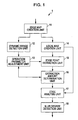
- Fig. 1 is a block diagram of an image processing apparatus according to an embodiment to which the present invention is applied.
- An image processing apparatus 1 in Fig. 1 analyzes as to whether or not a blur is generated in an edge point in an image which is input (hereinafter, referred to as input image), and on the basis of the analysis result, a blur state of the input image is detected.
- the image processing apparatus 1 is composed by including an edge map creation unit 11, a dynamic range detection unit 12, an operation parameter adjustment unit 13, a local max creation unit 14, an edge point extraction unit 15, an extraction amount determination unit 16, an edge analysis unit 17, and a blur degree detection unit 18.
- the edge map creation unit 11 detects an intensity of the edge of the input image (hereinafter, referred to as edge intensity) in units of three types of blocks having the different sizes of scales 1 to 3, and creates edge maps of the scales 1 to 3 (hereinafter, referred to as edge maps 1 to 3) in which the detected edge intensity is set as the pixel value as will be described below with reference to Fig. 2 .
- edge map creation unit 11 supplies the created edge maps 1 to 3 to the dynamic range detection unit 12 and the local max creation unit 14.
- the dynamic range detection unit 12 detects a dynamic range which is a difference between the maximum value and the minimum value of the edge intensity of the input image and supplies information representing the detected dynamic range to the operation parameter adjustment unit 13 as will be described below with reference to Fig. 2 .
- the operation parameter adjustment unit 13 adjusts an operation parameter used for extraction of the edge point so that the extraction amount of the edge point used for detection for the blur state of the input image (hereinafter, also referred to as edge point extraction amount) becomes an appropriate value as will be described below with reference to Fig. 2 .
- the operation parameters include an edge reference value used for determination as to whether or not this is the edge point and an extraction reference value used for determination as to whether or not the edge point extraction amount is appropriate.
- the operation parameter adjustment unit 13 supplies information representing the set edge reference value to the edge point extraction unit 15 and the extraction amount determination unit 16, and supplies information representing the set extraction reference value to the extraction amount determination unit 16.
- the local max creation unit 14 divides the edge maps 1 to 3 into respective blocks having predetermined sizes, and creates local maxes of the scales 1 to 3 (hereinafter, referred to as local maxes 1 to 3) by extracting a maximum value of the pixel value in each block as will be described below with reference to Fig. 2 .
- the local max creation unit 14 supplies the created local maxes 1 to 3 to the edge point extraction unit 15 and the edge analysis unit 17.
- the edge point extraction unit 15 extracts the edge points from the input image, and creates edge point tables of the scales 1 to 3 representing information of the extracted edge points (hereinafter, referred to as the edge point tables 1 to 3) to be supplied to the extraction amount determination unit 16 as will be described below with reference to Fig. 2 .
- the extraction amount determination unit 16 determines whether or not the edge point extraction amount is appropriate as will be described below with reference to Fig. 2 .
- the extraction amount determination unit 16 notifies the operation parameter adjustment unit 13 that the edge point extraction amount is not appropriate in a case where it is determined that the edge point extraction amount is not appropriate, and supplies the edge reference value at that time and the edge point tables 1 to 3 to the edge analysis unit 17 in a case where it is determined that the edge point extraction amount is appropriate.
- the edge analysis unit 17 performs analysis of the extracted edge points and supplies information representing the analysis result to the blur degree detection unit 18.
- the blur degree detection unit 18 detects a blur degree which is an index for the blur state of the input image as will be described below with reference to Fig. 2 .
- the blur degree detection unit 18 outputs information representing the detected blur degree to the outside.
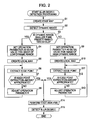
- the edge map creation unit 11 creates the edge map.
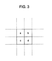
- the edge map creation unit 11 divides the input image into blocks having the size of 2 x 2 pixels, and on the basis of the following Expressions (1) to (6), calculates absolute values M TL_TR to M BL_BR which are differences of the pixel values between the pixels in the respective blocks.
- M TR_BL b - c 4
- a pixel value a denotes a pixel value of the pixel on the upper left in the block
- a pixel value b denotes a pixel value of the pixel on the upper right in the block
- a pixel value c denotes a pixel value of the pixel on the lower left in the block
- a pixel value d denotes a pixel value of the pixel on the lower right in the block.
- the mean value M Ave denotes a mean value of the edge intensities in the upper and lower, left and right, and oblique directions in the block.
- the edge map creation unit 11 creates the edge map 1 by arranging the calculated mean value M Ave in the same order as the corresponding block. Furthermore, in order to create the edge map 2 and the edge map 3, the edge map creation unit 11 creates averaged images of scales 2 and 3 on the basis of the following Expression (8).
- P m ⁇ n i + 1 P 2 ⁇ m , 2 ⁇ n i + P 2 ⁇ m , 2 ⁇ n + 1 i + P 2 ⁇ m + 1 , 2 ⁇ n i + P 2 ⁇ m + 1 , 2 ⁇ n + 1 i 4
- P i (x, y) represents a pixel value for a coordinate (x, y) of an averaged image of a scale i
- P i+1 (x, y) represents a pixel value for a coordinate (x, y) of an averaged image of a scale i+1.
- the averaged image of the scale 1 is an input image.
- the averaged image of the scale 2 is an image composed of a mean value of the pixel values of the respective blocks obtained by dividing the input image into blocks of the size of 2 x 2 pixels
- the averaged image of the scale 3 is an image composed of a mean value of the pixel values of the respective blocks obtained by dividing the averaged image of the scale 2 into blocks of the size of 2 x 2 pixels.
- the edge map creation unit 11 performs a similar processing on the averaged images of the scale 2 and the scale 3 to that performed on the input image by respectively using Expressions (1) to (7), and creates the edge map 2 and the edge map 3. Therefore, the edge maps 1 to 3 are images in which edge components in mutually different frequency bands of the scales 1 to 3 are extracted from the input image.
- the number of pixels in the edge map 1 is 1/4 (1/2 long x 1/2 width) of the input image
- the number of pixels in the edge map 2 is 1/16 (1/4 long x 1/4 width) of the input image
- the number of pixels in the edge map 3 is 1/64 (1/8 long x 1/8 width) of the input image.
- the edge map creation unit 11 supplies the created edge maps 1 to 3 to the dynamic range detection unit 12 and the local max creation unit 14.
- the dynamic range detection unit 12 detects the dynamic range.
- the dynamic range detection unit 12 detects the maximum value and the minimum value of the pixel values among the edge maps 1 to 3, and detects a value obtained by subtracting the detected minimum value from the maximum value of the pixel values, that is, a difference between the maximum value and the minimum value of the edge intensity of the input image, as the dynamic range.
- the dynamic range detection unit 12 supplies the information representing the detected dynamic range to the operation parameter adjustment unit 13. It should be noted that other than the above-mentioned method, for example, it is also conceivable that the dynamic range is detected for each edge map, and the maximum value, the mean value, or the like of the detected dynamic range is adopted as the actually used dynamic range.
- the operation parameter adjustment unit 13 determines whether the dynamic range is smaller than a predetermined threshold.
- step S4 the operation parameter adjustment unit 13 sets the operation parameters as an initial value for the image of the low dynamic range.
- the image of the low dynamic range has less edge as compared with an image of a high dynamic range, and the amount of the extracted edge point is small. Therefore, so as to be able to extract the sufficient amount of edge point to set the detection accuracy for the blur degree of the input image at equal to or higher than a certain level, an initial value of the edge reference value for the image of the low dynamic range is set as a smaller value than an initial value of the edge reference value for the image of the high dynamic range.
- an initial value of the extraction reference value for the image of the low dynamic range is set as a smaller value than an initial value of the extraction reference value for the image of the high dynamic range.
- the operation parameter adjustment unit 13 supplies the information representing the set edge reference value to the edge point extraction unit 15 and the extraction amount determination unit 16, and supplies the information representing the set extraction reference value to the extraction amount determination unit 16.
- the local max creation unit 14 creates the local max. To be more specific, as illustrated in the left side of Fig. 4 , the local max creation unit 14 divides the edge map 1 into blocks of 2 x 2 pixels, extracts the maximum value of each block, and arranges the extracted maximum values in the same order as the corresponding blocks to create the local max 1. Also, as illustrated in the center of Fig.
- the local max creation unit 14 divides the edge map 2 into blocks of 4 x 4 pixels, extracts the maximum value of each block, and arranges the extracted maximum values in the same order as the corresponding blocks to create the local max 2. Furthermore, as illustrated in the right side of Fig. 4 , the local max creation unit 14 divides the edge map 3 into blocks of 8 x 8 pixels, extracts the maximum value of each block, and arranges the extracted maximum values in the same order as the corresponding blocks to create the local max 3.
- the local max creation unit 14 supplies the created local maxes 1 to 3 to the edge point extraction unit 15 and the edge analysis unit 17. In step S6, the edge point extraction unit 15 extracts the edge point.
- the coordinate of the pixel of the local max 1 (x 1 , y 1 ) corresponding to the target pixel is calculated on the basis of the following Expression (9).
- x 1 ⁇ y 1 x / 4 , y / 4
- cutoff after the decimal point that is, one pixel of the local max 1 is generated from a block of 4 x 4 pixels of the input image, and therefore the coordinate of the pixel of the local max 1 corresponding to the target pixel of the input image takes 1/4 of the values of the x coordinate and the y coordinate of the target pixel.
- the edge point extraction unit 15 calculates the coordinate of the pixel of the local max 2 (x 2 , y 2 ) corresponding to the target pixel and the coordinate of the pixel of the local max 3 (x 3 , y 3 ) corresponding to the target pixel on the basis of the following Expression (10) and Expression (11).
- the edge point extraction unit 15 extracts the target pixel as the edge point in the local max 1, and stores the coordinate of the target pixel (x, y) and the pixel value of the coordinate of the local max 1 (x 1 , y 1 ) while being associated with each other.
- the edge point extraction unit 15 extracts the target pixel as the edge point in the local max 2, and stores the coordinate of the target pixel (x, y) and the pixel value of the coordinate of the local max 2 (x 2 , y 2 ) while being associated with each other, and in a case where the pixel value of the coordinate of the local max 3 (x 3 , y 3 ) is equal to or larger than the edge reference value, extracts the target pixel as the edge point in the local max 3, and stores the coordinate of the target pixel (x, y) and the pixel value of the coordinate of the local max 3 (x 3 , y 3 ) while being associated with each other.
- the edge point extraction unit 15 repeatedly performs the above-mentioned processing until all the pixels of the input image become target pixels, extracts the pixel included in the block where the edge intensity is equal to or larger than the edge reference value among the blocks of 4 x 4 pixels of the input image as the edge point on the basis of the local max 1, extracts the pixel included in the block where the edge intensity is equal to or larger than the edge reference value among the blocks of 16 x 16 pixels of the input image as the edge point on the basis of the local max 2, and extracts the pixel included in the block where the edge intensity is equal to or larger than the edge reference value among the blocks of 64 x 64 pixels of the input image as the edge point on the basis of the local max 3.
- the edge point extraction unit 15 create the edge point table 1 which is a table where the coordinate (x, y) of the edge point extracted on the basis of the local max 1 is associated with the pixel value of the pixel of the local max 1 corresponding to the edge point, the edge point table 2 which is a table where the coordinate (x, y) of the edge point extracted on the basis of the local max 2 is associated with the pixel value of the pixel of the local max 2 corresponding to the edge point, and the edge point table 3 which is a table where the coordinate (x, y) of the edge point extracted on the basis of the local max 3 s associated with the pixel value of the pixel of the local max 3 corresponding to the edge point to be supplied to the extraction amount determination unit 16.
- step S7 the extraction amount determination unit 16 determines whether the edge point extraction amount is appropriate.
- the extraction amount determination unit 16 compares the total number of extracted edge points, that is, the total of data pieces of the edge point tables 1 to 3 with the extraction reference value, and determines that the edge point extraction amount is not appropriate in a case where the total number is smaller than the extraction reference value, and the processing is advanced to step S8.
- the operation parameter adjustment unit 13 adjusts the operation parameters. To be more specific, the extraction amount determination unit 16 notifies the operation parameter adjustment unit 13 that the edge point extraction amount is not appropriate.
- the operation parameter adjustment unit 13 sets the edge reference value smaller by a predetermined value so that more edge points are to be extracted than the current number.
- the operation parameter adjustment unit 13 supplies information representing the adjusted edge reference value to the edge point extraction unit 15 and the extraction amount determination unit 16. After that, the processing is returned to step S6, and until it is determined in step S7 that the edge point extraction amount is appropriate, the processing in steps S6 to S8 is repeatedly executed. That is, until the edge point extraction amount becomes an appropriate value, the edge point is extracted while the edge reference value is adjusted, and the processing of creating the edge point tables 1 to 3 is repeatedly performed. On the other hand, in step S7, in a case where the total number of extracted edge points is equal to or larger than the extraction reference value, the extraction amount determination unit 16 determines that the edge point extraction amount is appropriate, and the processing is advanced to step S14.
- step S3 in a case where it is determined that the dynamic range is equal to or larger than the predetermined threshold, that is, this is the high dynamic range, the processing is advanced to step S9.
- step S9 the operation parameter adjustment unit 13 sets the operation parameters as the initial value for the image of the high dynamic range.
- the image of the high dynamic range has more edge as compared with the image of the low dynamic range, and it is estimated that the amount of extracted edge points is large.
- the initial value of the edge reference value for the image of the high dynamic range is set as a larger value as compared with the initial value of the edge reference value for the image of the low dynamic range so that the pixel included in the block where the edge intensity is more strong can be extracted as the edge point.
- the initial value of the extraction reference value for the image of the high dynamic range is set as a larger value as compared with the initial value of the extraction reference value for the image of the low dynamic range.
- the operation parameter adjustment unit 13 supplies the information representing the set edge reference value to the edge point extraction unit 15 and the extraction amount determination unit 16, and supplies the information representing the set extraction reference value to the extraction amount determination unit 16.
- step S10 similarly to the processing in step S5, the local maxes 1 to 3 are created, and the created local maxes 1 to 3 are supplied to the edge point extraction unit 15 and the edge analysis unit 17.
- step S11 similarly to the processing in step S6, the edge point tables 1 to 3 are created, and the created edge point tables 1 to 3 are supplied to the extraction amount determination unit 16.
- step S12 similarly to the processing in step S7, it is determined as to whether the edge point extraction amount is appropriate, and in a case where it is determined that the edge point extraction amount is not appropriate, the processing is advanced to step S13.
- step S13 similarly to the processing in step S8, the operation parameters are adjusted, after that, the processing is returned to step S11, and in step S12, until it is determined that the edge point extraction amount is appropriate, the processing in steps S11 to S13 is repeatedly executed.
- step S12 in a case where it is determined that the edge point extraction amount is appropriate, the processing is advanced to step S14.
- the edge point is also extracted from the block where the edge intensity is weak so that the sufficient amounts of the edge points to set the detection accuracy for the blur degree of the input image equal to or higher than the certain level can be ensured, and regarding the input image of the high dynamic range, the edge point is extracted from the block where the edge intensity is strong as much as possible so that the edge point constituting the stronger edge can be extracted.
- the edge analysis unit 17 performs an edge analysis. To be more specific, the extraction amount determination unit 16 supplies the edge reference value at the moment when it is determined that the edge point extraction amount is appropriate and the edge point tables 1 to 3 to the edge analysis unit 17.
- the edge analysis unit 17 selects one of the edge points extracted from the input image as the target pixel on the basis of the edge point tables 1 to 3. In a case where the coordinate of the selected target pixel is set as (x, y), the edge analysis unit 17 calculates the coordinate (x 1 , y 1 ) to the coordinate (x 3 , y 3 ) of the pixels of the local maxes 1 to 3 corresponding to the target pixel on the basis of the above-mentioned Expressions (9) to (11).
- the edge analysis unit 17 sets as Local Max 1 (x 1 , y 1 ) the maximum value of the pixel value in the block of m x m pixels (for example, 4 x 4 pixels) where the pixel of the coordinate of the local max 1 (x 1 , y 1 ) is the pixel at the upper left corner, sets as Local Max 2 (x 2 , y 2 ) the maximum value of the pixel value in the block of n x n pixels (for example, 2 x 2 pixels) where the pixel of the coordinate of the local max 2 (x 2 , y 2 ) is the pixel at the upper left corner, and sets as Local Max 3 (x 3 , y 3 ) the pixel of the coordinate of the local max 3 (x 3 , y 3 ).
- parameters in m x m used for the setting for Local Max 1 (x 1 , y 1 ) and n x n used for the setting for Local Max 2 (x 2 , y 2 ) are parameters for adjusting the difference in sizes of the blocks of the input image corresponding to the one pixel of the local maxes 1 to 3.
- the edge analysis unit 17 determines whether or not Local Max 1 (x 1 , y 1 ), Local Max 2 (x 2 , y 2 ), and Local Max 3 (x 3 , y 3 ) satisfy the following conditional expression (12).
- the edge analysis unit 17 increments a value of a variable N edge by one.
- Local max 1 x 1 ⁇ y 1 edge reference value or 12
- Local max 2 x 2 ⁇ y 2 edge reference value or
- Local max 3 x 3 ⁇ y 3 Local max 3 x 3 ⁇ y 3
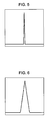
- the edge point which satisfies the conditional expression (12) is estimated to be an edge point constituting an edge having an intensity equal to or larger than a certain level irrespective of the structure, such as a steep impulse like edge shown in Fig.
- the edge analysis unit 17 further determines whether or not the following conditional expression (13) or the conditional expression (14) is satisfied.
- the edge analysis unit 17 increments a value of a variable N smallblur by one.
- the edge analysis unit 17 determines whether or not Local Max 1 (x 1 , y 1 ) satisfies the following conditional expression (15). In a case where Local Max 1 (x 1 , y 1 ) satisfies the conditional expression (15), the edge analysis unit 17 increments a value of a variable N largelblur by one. Local max 1 x 1 ⁇ y 1 > edge reference value
- the edge point which satisfies the conditional expression (12), satisfies the conditional expression (13) or the conditional expression (14), and also satisfies the conditional expression (15) is estimated to be an edge point which constitutes an edge in which a blur is generated and sharpness is lost among the edges having the structure of Fig. 6 or 8 whose intensity is equal to or larger than the certain level. In other words, it is estimated that the blur is generated in the edge point.
- the edge analysis unit 17 repeatedly performs the above-mentioned processing until all the edge points extracted from the input image become the target pixels. With this configuration, among the extracted edge points, the number of edge points N edge satisfying the conditional expression (13), the number of edge points N smallblur satisfying the conditional expression (12) and also satisfying the conditional expression (13) or the conditional expression (14), and the number of edge points N largelblur satisfying the conditional expression (12), satisfying the conditional expression (13) or the conditional expression (14), and also satisfying the conditional expression (15) are calculated.
- the edge analysis unit 17 supplies information representing the calculated N smallblur and N largelblur to the blur degree detection unit 18.
- step S15 the blur degree detection unit 18 detects a blur degree BlurEstimation which is an index for the blur state of the input image on the basis of the following Expression (16).
- BlurEstimation N largeblur N smallbur
- the blur degree BlurEstimation is a ratio occupied by the edge points estimated to constitute the edge in which the blur is generated among the edge points estimated to constitute the edge having the structure of Fig. 6 or 8 whose intensity is equal to or larger than the certain level. Therefore, it is estimated that as the blur degree BlurEstimation is larger, the blur state of the input image is larger, and as the blur degree BlurEstimation is smaller, the blur state of the input image is smaller.
- the blur degree detection unit 18 outputs the detected blur degree BlurEstimation to the outside, and the blur degree detection processing is ended.
- the external apparatus determines whether or not the input image is blurred by comparing the blur degree BlurEstimation with a predetermined threshold.
- the condition for extracting the edge point and the edge point extraction amount are appropriately controlled, and it is therefore possible to detect the blur state of the input image at a higher accuracy.
- the edge intensity is detected without performing a complicated operation such as a wavelet transform, and it is therefore possible to shorten the period of time for detecting the edge intensity as compared with the invention disclosed in "Blur Detection for Digital Images Using Wavelet Transform".
- An image processing apparatus 101 shown in Fig. 9 is configured to include an edge map creation unit 111, a dynamic range detection unit 112, an operation parameter adjustment unit 113, a local max creation unit 114, an edge point extraction unit 115, an extraction amount determination unit 116, an edge analysis unit 117, a blur degree detection unit 118 and an image size detection unit 119.
- parts in the present figure, which correspond to ones in Fig. 1 are designated by numbers having the same last two digit values in both figures, respectively. To avoid repetition of the description, explanation is omitted for the part performing the same processing as that of Fig. 1
- the size detection unit 119 detects an image size (the number of pixels) of input image, and provides the operation parameter adjustment unit 113 with information indicating a detected image size of input image.
- the operation parameter adjustment unit 113 adjusts operation parameters that include an edge reference value and an extraction reference value based on the detected image size and a dynamic range of input image, as it will be explained below.
- the operation parameter adjustment unit 113 provides the edge point extraction unit 115 and the extraction amount determination unit 116 with information indicating an edge reference value set, and provides the extraction amount determination unit 116 with information indicating an extraction reference value set.
- Such processing starts, for example, if an input image that becomes a detection subject is input to the edge map creation unit 111 and the image size detection unit 119.
- Steps S101 and S102 are similar to those of Steps S1 and S2. To avoid repetition, the explanation thereof is omitted. According to such processing, the edge map of the input image is created and the dynamic range of the input image is detected.
- the image size detection unit 119 detects an image size. For example, the image size detection unit 119 detects the numbers of pixels of the image size in longitudinal and lateral directions as the image size. The image size detection unit 119 provides the operation parameter adjustment unit 113 with information indicating the detected image size.
- Step S104 the operation parameter adjustment unit 113 determines if the image size is equal to a predetermined threshold value or larger.
- the operation parameter adjustment unit 113 determines that the image size is not equal to the predetermined threshold value or larger if the numbers of pixels of the input image is less than the predetermined threshold value (For example, 256 x 256 pixels), and then the processing advances to Step S105.
- Step S105 to S115 Processing performed in Steps S105 to S115 is similar to that of Steps S3 to S13. To avoid repetition, the explanation thereof is omitted. According to such processing, the edge point is extracted from an input image having the image size less than the predetermined threshold value while adjusting the edge reference value and the extraction reference value. Subsequently, the processing proceeds to Step S127.
- Step S104 If the image size is determined as equal to or larger than the predetermined threshold value in Step S104, the processing proceeds to Step S116.
- Step S116 to S126 Processing performed in Steps S116 to S126 is similar to that of Steps S3 to S13. To avoid repetition, the explanation thereof is omitted. According to such processing, the edge point is extracted from an input image having the image size equal to or larger than the predetermined threshold value while adjusting the edge reference value and the extraction reference value. Subsequently, the processing proceeds to Step S127.
- initial values of the edge reference value and the extraction reference value set in Steps S106, S111, S117 and S122 are different from each other.
- one pair is selected from four kinds of initial value pairs for the edge reference value and the extraction value based on the image size and dynamic range of input image.
- the smaller initial value is set for the extraction reference value if the image size is less than the predetermined threshold value, as compared to a case where the image size is equal to the predetermined threshold value or larger. The same applies to images with high dynamic range.
- the reason for this is the following. It is estimated that, if images have the same dynamic range, an amount of edge points extracted is smaller in the smaller size image since there are less edges in the smaller image. Accordingly, it may be possible that accuracy of the edge point extraction may become less if the same number of the edge point is extracted from the smaller size image as that of the larger size image. In order to avoid such a case, if the image size is less than the predetermined threshold value, the initial value of the extraction reference value is set to a smaller value than the initial value set for a case where the image size is equal to the predetermined threshold value or larger.
- Steps S127 and S128 are similar to those in Steps S14 and S15. To avoid repetition, the explanation thereof is omitted. According to such processing, the edge analysis of each pixel of the input image is performed, and based on results of the edge analysis, the degree of blur "BlurEstimation" of the input image is detected. Subsequently, the blur detection processing ends.
- the initial values of the edge reference value and the extraction reference value are set in consideration of not only the dynamic range of input image but also its image size. Accordingly, the blur degree of an input image is detectable in high precision.
- the above-mentioned description shows the example of calculating the mean value of the edge intensities in the three directions of upper and lower, left and right, and oblique directions in the block in a case where the edge map is created, but for example, the mean value of the edge intensities in one direction or two directions may be calculated.
- the above-mentioned description shows the example of performing the processing while the input image is classified into two types of the high dynamic range and the low dynamic range, but such a configuration may be adopted that classification into three or more types is performed depending on a range of the dynamic range, and as the dynamic range is larger, the initial values of the edge reference value and the extraction reference value are set as larger values, and as the dynamic range is smaller, the initial values of the edge reference value and the extraction reference value are set as smaller values.
- the blur state of the input image can be detected at a higher accuracy.
- the above-mentioned description shows the example of setting the small edge reference value in a case where the amount of extracted edge points is too small so that more edge points are to be extracted, but furthermore, the edge reference value may be set larger in a case where the amount of extracted edge points is too large so that the amount of edge points to be extracted is decreased. That is, the edge reference value may be adjusted in a direction where the edge point extraction amount becomes an appropriate amount.
- the processing may be performed while treating as the input image of the high dynamic range.
- the size of the block in a case where the above-mentioned edge map and the local max are created is the one example, and can also be set as a size different from the above-mentioned size.
- the image size of input image is classified in two types and performed processing accordingly.
- the image size may be classified into three types or more.
- the larger initial value may be set for the extraction reference value as the image size becomes larger, and the smaller initial value may be set for the extraction reference value as the image size becomes smaller. Accordingly, the blur of an input image may be detectable in higher precession.
- the initial value of the edge reference value may be changed in accordance with the image size of input image.
- the threshold value to be used in classifying the dynamic range of input image may be changed in accordance with the image size of input image.
- the above-mentioned series of processing can also be executed by hardware and can also be executed by software.
- a program constituting the software is installed from a program recording medium into a computer incorporated in dedicated use hardware or, for example, a general-use personal computer or the like which can execute various functions through installment of various programs.
- Fig. 11 is a block diagram of a hardware configuration example of a computer executing the above-mentioned series of processing by way of a program.
- a CPU Central Processing Unit
- ROM Read Only Memory
- RAM Random Access Memory
- an input and output interface 205 is connected to the bus 204.
- an input unit 206 composed of a keyboard, a mouse, a microphone, and the like
- an output unit 207 composed of a display, a speaker, and the like
- a storage unit 208 composed of a hard disc drive, a non-volatile memory, and the like
- a communication unit 209 composed of a network interface and the like
- a drive 210 for driving a removal media 211 such as a magnetic disc, an optical disc, an opto-magnetic disc, or a semiconductor memory are connected.
- the CPU 201 loads and executes the program stored, for example, in the storage unit 208 onto the RAM 203 via the input and output interface 205 and the bus 204 to perform the above-mentioned series of processing.
- the program executed by the computer (the CPU 201) is recorded, for example, on the removal media 211 functioning as a package media composed of the magnetic disc (including a flexible disc), the optical disc (a CD-ROM (Compact Disc-Read Only Memory), a DVD (Digital Versatile Disc) or the like), the opto-magnetic disc, or the semiconductor memory, or the like, or is provide via a wired or wireless transmission medium such as a local area network, the internet, or digital satellite broadcasting.
- the removal media 211 functioning as a package media composed of the magnetic disc (including a flexible disc), the optical disc (a CD-ROM (Compact Disc-Read Only Memory), a DVD (Digital Versatile Disc) or the like), the opto-magnetic disc, or the semiconductor memory, or the like, or is provide via a wired or wireless transmission medium such as a local area network, the internet, or digital satellite broadcasting.
- the program can be installed via the input and output interface 205 in the storage unit 208 by mounting the removal media 211 to the drive 210. Also, the program can be installed in the storage unit 208 while being received by the communication unit 209 via the wired or wireless transmission medium. In addition, the program can be installed in the ROM 202 or the storage unit 208 in advance.
- the program executed by the computer may be a program in which a processing is performed in a time series manner along with the order described in the present specification, or may also be a program in which a processing is performed in parallel or at a requested timing such as a call is performed.
Landscapes
- Engineering & Computer Science (AREA)
- Computer Vision & Pattern Recognition (AREA)
- Physics & Mathematics (AREA)
- General Physics & Mathematics (AREA)
- Theoretical Computer Science (AREA)
- Multimedia (AREA)
- Quality & Reliability (AREA)
- Image Analysis (AREA)
- Image Processing (AREA)
- Studio Devices (AREA)
- Facsimile Image Signal Circuits (AREA)
Applications Claiming Priority (1)
| Application Number | Priority Date | Filing Date | Title |
|---|---|---|---|
| JP2007325511 | 2007-12-18 |
Publications (1)
| Publication Number | Publication Date |
|---|---|
| EP2073169A2 true EP2073169A2 (fr) | 2009-06-24 |
Family
ID=40352306
Family Applications (1)
| Application Number | Title | Priority Date | Filing Date |
|---|---|---|---|
| EP08254011A Withdrawn EP2073169A2 (fr) | 2007-12-18 | 2008-12-16 | Appareil de traitement d'image et procédé et programme |
Country Status (4)
| Country | Link |
|---|---|
| US (1) | US8300969B2 (fr) |
| EP (1) | EP2073169A2 (fr) |
| JP (1) | JP5093083B2 (fr) |
| CN (1) | CN101465000B (fr) |
Cited By (3)
| Publication number | Priority date | Publication date | Assignee | Title |
|---|---|---|---|---|
| CN101872484A (zh) * | 2010-06-30 | 2010-10-27 | 西安电子科技大学 | 图像域中多个微弱目标航迹自适应生长检测方法 |
| CN101969570B (zh) * | 2009-07-27 | 2013-04-17 | 慧帝科技(深圳)有限公司 | 图像的边界系数计算方法以及图像噪声去除方法 |
| WO2013148566A1 (fr) * | 2012-03-26 | 2013-10-03 | Viewdle, Inc. | Détection de flou d'image |
Families Citing this family (10)
| Publication number | Priority date | Publication date | Assignee | Title |
|---|---|---|---|---|
| US7720302B2 (en) * | 2003-09-25 | 2010-05-18 | Fujifilm Corporation | Method, apparatus and program for image processing |
| JP4406443B2 (ja) * | 2007-05-09 | 2010-01-27 | 株式会社東芝 | 画像補正装置 |
| US20100166257A1 (en) * | 2008-12-30 | 2010-07-01 | Ati Technologies Ulc | Method and apparatus for detecting semi-transparencies in video |
| JP5136474B2 (ja) * | 2009-03-13 | 2013-02-06 | ソニー株式会社 | 画像処理装置および方法、学習装置および方法、並びに、プログラム |
| EP2609853A4 (fr) | 2010-08-27 | 2016-03-09 | Sony Corp | Appareil et procédé de traitement d'image |
| JP5800187B2 (ja) * | 2011-08-16 | 2015-10-28 | リコーイメージング株式会社 | 撮像装置および距離情報取得方法 |
| CN102508726B (zh) * | 2011-11-14 | 2014-07-30 | 福建星网锐捷网络有限公司 | 内存参数配置方法、处理器及设备 |
| JP6748020B2 (ja) * | 2017-04-10 | 2020-08-26 | ニッタ株式会社 | 判定システム及び判定プログラム |
| JP2024110493A (ja) * | 2023-02-03 | 2024-08-16 | キヤノン株式会社 | 画像処理装置、撮像装置および画像処理方法 |
| US20250252624A1 (en) * | 2024-02-05 | 2025-08-07 | Adobe Inc. | Sketch to image generation using control network |
Citations (1)
| Publication number | Priority date | Publication date | Assignee | Title |
|---|---|---|---|---|
| JP2007325511A (ja) | 2006-06-06 | 2007-12-20 | Kyoto Univ | 直鎖状化合物伸長方法、直鎖状化合物伸長装置及び伸長された直鎖状化合物を含む高分子フィルム |
Family Cites Families (8)
| Publication number | Priority date | Publication date | Assignee | Title |
|---|---|---|---|---|
| US7257273B2 (en) * | 2001-04-09 | 2007-08-14 | Mingjing Li | Hierarchical scheme for blur detection in digital image using wavelet transform |
| US6888564B2 (en) * | 2002-05-24 | 2005-05-03 | Koninklijke Philips Electronics N.V. | Method and system for estimating sharpness metrics based on local edge kurtosis |
| US7099518B2 (en) * | 2002-07-18 | 2006-08-29 | Tektronix, Inc. | Measurement of blurring in video sequences |
| CN1177298C (zh) * | 2002-09-19 | 2004-11-24 | 上海交通大学 | 基于块分割的多聚焦图像融合方法 |
| DE10393783T5 (de) * | 2002-11-28 | 2005-10-27 | Advantest Corp. | Positionserfassungsvorrichtung, Positionserfassungsverfahren und Tragvorrichtung für elektronische Komponenten |
| JP4493416B2 (ja) * | 2003-11-26 | 2010-06-30 | 富士フイルム株式会社 | 画像処理方法および装置並びにプログラム |
| CN101019167A (zh) * | 2004-09-03 | 2007-08-15 | 皇家飞利浦电子股份有限公司 | 针对LCD视频/图形处理器的廉价运动模糊减小(eco-过激励) |
| US20090079862A1 (en) * | 2007-09-25 | 2009-03-26 | Micron Technology, Inc. | Method and apparatus providing imaging auto-focus utilizing absolute blur value |
-
2008
- 2008-12-12 JP JP2008316388A patent/JP5093083B2/ja not_active Expired - Fee Related
- 2008-12-16 EP EP08254011A patent/EP2073169A2/fr not_active Withdrawn
- 2008-12-16 US US12/336,477 patent/US8300969B2/en not_active Expired - Fee Related
- 2008-12-18 CN CN200810183592XA patent/CN101465000B/zh not_active Expired - Fee Related
Patent Citations (1)
| Publication number | Priority date | Publication date | Assignee | Title |
|---|---|---|---|---|
| JP2007325511A (ja) | 2006-06-06 | 2007-12-20 | Kyoto Univ | 直鎖状化合物伸長方法、直鎖状化合物伸長装置及び伸長された直鎖状化合物を含む高分子フィルム |
Non-Patent Citations (1)
| Title |
|---|
| HANGHANG TONG ET AL.: "Blur Detection for Digital Images Using Wavelet Transform", MULTIMEDIA AND EXPO, 2004. ICME '04. 2004 IEEE INTERNATIONAL, 27 June 2004 (2004-06-27), pages 17 - 20, XP010770733, DOI: doi:10.1109/ICME.2004.1394114 |
Cited By (5)
| Publication number | Priority date | Publication date | Assignee | Title |
|---|---|---|---|---|
| CN101969570B (zh) * | 2009-07-27 | 2013-04-17 | 慧帝科技(深圳)有限公司 | 图像的边界系数计算方法以及图像噪声去除方法 |
| CN101872484A (zh) * | 2010-06-30 | 2010-10-27 | 西安电子科技大学 | 图像域中多个微弱目标航迹自适应生长检测方法 |
| CN101872484B (zh) * | 2010-06-30 | 2012-06-27 | 西安电子科技大学 | 图像域中多个微弱目标航迹自适应生长检测方法 |
| WO2013148566A1 (fr) * | 2012-03-26 | 2013-10-03 | Viewdle, Inc. | Détection de flou d'image |
| US9361672B2 (en) | 2012-03-26 | 2016-06-07 | Google Technology Holdings LLC | Image blur detection |
Also Published As
| Publication number | Publication date |
|---|---|
| US20090214121A1 (en) | 2009-08-27 |
| CN101465000A (zh) | 2009-06-24 |
| US8300969B2 (en) | 2012-10-30 |
| JP2009169943A (ja) | 2009-07-30 |
| CN101465000B (zh) | 2011-10-05 |
| JP5093083B2 (ja) | 2012-12-05 |
Similar Documents
| Publication | Publication Date | Title |
|---|---|---|
| EP2073169A2 (fr) | Appareil de traitement d'image et procédé et programme | |
| US8724917B2 (en) | Selecting best image among sequentially captured images | |
| EP2819091B1 (fr) | Procédé et appareil de traitement d'une image en demi-teintes | |
| EP3483767A1 (fr) | Dispositif de détection d'un code malveillant variant sur la base d'un apprentissage de réseau neuronal, procédé associé, et support d'enregistrement lisible par ordinateur dans lequel un programme d'exécution dudit procédé est enregistré | |
| US20040264741A1 (en) | Region detecting method and region detecting apparatus | |
| CN112037185B (zh) | 染色体分裂相图像筛选方法、装置及终端设备 | |
| KR102165273B1 (ko) | 소형 뉴럴 네트워크의 채널 프루닝(pruning) 방법 및 시스템 | |
| US9418410B2 (en) | Image processing apparatus and method thereof | |
| US8363909B2 (en) | Image processing apparatus, image processing method, and computer program product | |
| KR20000076565A (ko) | 다수의 영상 사이의 유사도 레벨을 결정하기 위한 시스템및 방법과, 그러한 결정을 인에이블하기 위한 세그먼트데이터 구조 | |
| US11995153B2 (en) | Information processing apparatus, information processing method, and storage medium | |
| US20060109510A1 (en) | Methods and systems for determining object layouts | |
| US20080089588A1 (en) | Rotation angle detection apparatus, and control method and control program of rotation angle detection apparatus | |
| US20040091146A1 (en) | Representative color designating method using reliability | |
| EP3306527A1 (fr) | Procédé de rognage d'image, appareil de rognage d'image, programme et support de stockage | |
| US20120099762A1 (en) | Image processing apparatus and image processing method | |
| EP2226763B1 (fr) | Procédé de traitement d'image et appareil de détection de bord d'un objet dans une image | |
| EP2234388A1 (fr) | Appareil et procédé de vérification d'objet | |
| US8873839B2 (en) | Apparatus of learning recognition dictionary, and method of learning recognition dictionary | |
| TW200931949A (en) | System for applying multi-direction and multi-slope region detection to image edge enhancement | |
| CN113255648B (zh) | 一种基于图像识别的滑动窗口框选方法及终端 | |
| EP3438923A1 (fr) | Appareil et procédé de traitement d'images | |
| JP2007047975A (ja) | デジタル画像の複数対象物検出方法および装置並びにプログラム | |
| CN111242880B (zh) | 一种用于显微镜的多景深图像叠加方法、设备及介质 | |
| EP2012256A2 (fr) | Appareil de traitement d'images, procédé de traitement d'images et produit de programme informatique |
Legal Events
| Date | Code | Title | Description |
|---|---|---|---|
| PUAI | Public reference made under article 153(3) epc to a published international application that has entered the european phase |
Free format text: ORIGINAL CODE: 0009012 |
|
| 17P | Request for examination filed |
Effective date: 20081227 |
|
| AK | Designated contracting states |
Kind code of ref document: A2 Designated state(s): AT BE BG CH CY CZ DE DK EE ES FI FR GB GR HR HU IE IS IT LI LT LU LV MC MT NL NO PL PT RO SE SI SK TR |
|
| AX | Request for extension of the european patent |
Extension state: AL BA MK RS |
|
| STAA | Information on the status of an ep patent application or granted ep patent |
Free format text: STATUS: THE APPLICATION IS DEEMED TO BE WITHDRAWN |
|
| 18D | Application deemed to be withdrawn |
Effective date: 20140701 |