EP2073224B1 - Kondensatorschutzvorrichtung - Google Patents
Kondensatorschutzvorrichtung Download PDFInfo
- Publication number
- EP2073224B1 EP2073224B1 EP08354075.7A EP08354075A EP2073224B1 EP 2073224 B1 EP2073224 B1 EP 2073224B1 EP 08354075 A EP08354075 A EP 08354075A EP 2073224 B1 EP2073224 B1 EP 2073224B1
- Authority
- EP
- European Patent Office
- Prior art keywords
- blade
- holder
- conductor
- knife holder
- breaking
- Prior art date
- Legal status (The legal status is an assumption and is not a legal conclusion. Google has not performed a legal analysis and makes no representation as to the accuracy of the status listed.)
- Active
Links
- 239000003990 capacitor Substances 0.000 title claims description 37
- 239000004020 conductor Substances 0.000 claims description 53
- 239000012528 membrane Substances 0.000 claims description 22
- 230000002093 peripheral effect Effects 0.000 claims description 12
- 230000001681 protective effect Effects 0.000 claims description 11
- 230000000694 effects Effects 0.000 claims description 4
- 230000006835 compression Effects 0.000 description 11
- 238000007906 compression Methods 0.000 description 11
- 239000007789 gas Substances 0.000 description 8
- 238000006073 displacement reaction Methods 0.000 description 6
- 238000000354 decomposition reaction Methods 0.000 description 5
- 239000000463 material Substances 0.000 description 5
- 230000007547 defect Effects 0.000 description 3
- 238000004519 manufacturing process Methods 0.000 description 3
- 238000004804 winding Methods 0.000 description 3
- 230000001133 acceleration Effects 0.000 description 2
- 238000000926 separation method Methods 0.000 description 2
- 230000002159 abnormal effect Effects 0.000 description 1
- 238000004873 anchoring Methods 0.000 description 1
- 230000008033 biological extinction Effects 0.000 description 1
- 238000005266 casting Methods 0.000 description 1
- 230000015556 catabolic process Effects 0.000 description 1
- 238000004146 energy storage Methods 0.000 description 1
- 238000001704 evaporation Methods 0.000 description 1
- 230000008020 evaporation Effects 0.000 description 1
- 238000001914 filtration Methods 0.000 description 1
- 239000000499 gel Substances 0.000 description 1
- 230000002452 interceptive effect Effects 0.000 description 1
- 230000008018 melting Effects 0.000 description 1
- 238000002844 melting Methods 0.000 description 1
- 239000002184 metal Substances 0.000 description 1
- 238000000034 method Methods 0.000 description 1
- 239000003921 oil Substances 0.000 description 1
- 230000000750 progressive effect Effects 0.000 description 1
- 239000011347 resin Substances 0.000 description 1
- 229920005989 resin Polymers 0.000 description 1
- 125000006850 spacer group Chemical group 0.000 description 1
Images






Classifications
-
- H—ELECTRICITY
- H01—ELECTRIC ELEMENTS
- H01G—CAPACITORS; CAPACITORS, RECTIFIERS, DETECTORS, SWITCHING DEVICES, LIGHT-SENSITIVE OR TEMPERATURE-SENSITIVE DEVICES OF THE ELECTROLYTIC TYPE
- H01G2/00—Details of capacitors not covered by a single one of groups H01G4/00-H01G11/00
- H01G2/14—Protection against electric or thermal overload
- H01G2/18—Protection against electric or thermal overload with breakable contacts
-
- H—ELECTRICITY
- H01—ELECTRIC ELEMENTS
- H01G—CAPACITORS; CAPACITORS, RECTIFIERS, DETECTORS, SWITCHING DEVICES, LIGHT-SENSITIVE OR TEMPERATURE-SENSITIVE DEVICES OF THE ELECTROLYTIC TYPE
- H01G2/00—Details of capacitors not covered by a single one of groups H01G4/00-H01G11/00
- H01G2/14—Protection against electric or thermal overload
Definitions
- the invention relates to the field of capacitors, in particular power capacitors having a self-healing property, also known as self-healing capacitors.
- Power capacitors are generally used to perform reactive energy compensation in electrical networks or in the manufacture of harmonic filtering systems.
- These capacitors generally comprise at least one wound winding made from two layers of insulating film on which a conductive metal layer has been deposited.
- the windings are generally surrounded by a material such as resin, oil, gel or gas.
- the presence of a defect in the insulating film may cause localized breakdown leading to the evaporation of the electrodes in the vicinity of the defect.
- the self-healing properties can be deteriorated.
- the increase of the current between the capacitor plates can cause an increase in the temperature in the vicinity of the defect and a production of decomposition gas of the insulating film whose pressure can cause the rupture of the envelope.
- the patent application FR 2,589,618 discloses a capacitor protection device having a fuse connected in series with one of the capacitor plates, this fuse being destroyed by melting upon the occurrence of a fault current.
- This device further comprises a piston for causing the rupture of the fuse when the pressure of the decomposition gases inside the capacitor box exceeds a safety value.
- a disadvantage of the aforementioned device is that the force available to break the fuse depends on the pressure of the decomposition gases generated and the pressure rise rate of these gases.
- the breaking means comprise means for accumulating an energy necessary to break the conductor, and locking and unlocking means for releasing said energy when the breaking means are actuated.
- the breaking means are actuated when the moving part is moved beyond a limit position corresponding to the exceeding of the trigger threshold.
- the breaking means comprise a knife and a knife holder on which the knife is fixedly mounted.
- the knife holder is movably mounted in the housing and is rotatable about the longitudinal axis.
- the device comprises means for guiding rotation of the knife holder.
- the energy storage means may comprise a torsion spring mounted between the knife holder and the housing, said spring being bandaged when the knife holder is in an armed position.
- the locking and unlocking means further enable the knife holder to be held in the armed position.
- the knife holder is also movable in a translation movement along the longitudinal axis.
- the protuberance is disposed on an inner surface of the housing, and the axial slide is disposed on a peripheral outer surface of the knife holder.
- the means for holding the protuberance in the axial slideway comprise return means mounted between the knife holder and the housing for applying to the knife holder a restoring force and for holding the knife holder in the armed position.
- the knife holder comprises spacing means of the ends of the driver appearing consecutively to the breakage of the conductor.
- the spacer means comprise a chute disposed in the knife holder in which at least a portion of the fracturable conductor is housed so that, following the fracture of the fracturable conductor, said portion of the fracturable conductor is caused by rotation. of the knife holder.
- the mobile part consists essentially of a mobile central part of a deformable membrane having a peripheral portion intended to be mounted on the housing.
- the peripheral portion is hermetically mounted on the housing to isolate a volume comprising the fracturable conductor.
- the membrane is of the blistering type.
- the fracturable conductor comprises a fuse element.
- the invention also relates to a capacitor equipped with two armatures and having a protection device of said capacitor as described above, said device comprising a fracturable conductor connected in series with one of the armatures.
- the figure 1 represents a perspective view from above of an embodiment of the device of the invention.
- the figure 2 represents a perspective view from below of the device of the figure 1 wherein the movable portion is in an initial position.
- the figure 3 represents a perspective view from below of the device of the figure 1 wherein the movable portion is in a position causing the unlocking of the energy necessary to break the conductor.
- the figure 4 represents a system of three capacitors, one of which is equipped with a protection device according to the invention.
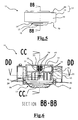
- the figure 5 represents a side view of the device shown in figure 2 .
- the figure 6 is a longitudinal sectional view along the axis BB-BB of the device shown in FIG. figure 2 .
- the figure 7 is a cross-sectional view along the DD-DD axis of the device shown in FIG. figure 2 .
- the figure 8 is a detailed longitudinal sectional view of a portion of the device shown in FIG. figure 2 .
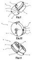
- the figure 9 is a side perspective view of the knife holder.
- the figure 10 is a perspective view from above of the knife holder shown in FIG. figure 9 .
- the figure 11 is a perspective view from below of the knife holder shown in FIG. figure 9 .
- the figure 12 is a longitudinal sectional view along the CC-CC axis of the device shown in FIG. figure 2 wherein the movable portion is in an initial position.
- the figure 13 is a bottom view, without the membrane, of the device shown in FIG. figure 12 .
- the figure 14 is a longitudinal sectional view along the CC-CC axis of the device shown in FIG. figure 2 wherein the movable portion is in a position causing the unlocking of the energy necessary to break the conductor.
- the figure 15 is a bottom view, without the membrane, of the device shown in FIG. figure 14 .
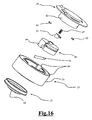
- the figure 16 is an exploded view of different parts of an embodiment of the protection device.
- FIGS. 17a, 17b and 17c represent schematic sections of an embodiment of the protection device according to the invention in which the knife holder is in different positions.
- the protective device 11 comprises a housing 12 having a cover 13 and a cap 14 covering said cover.
- the housing cap has openings 15 and 16 for the passage of the connecting conductors with the capacitor plates on which the protective device is to be mounted.
- the housing 12 of the protective device is assembled by covering the cover 13 with the cap 14.
- the outer surface of a side wall 63 of the cap cooperates with the inner surface 21 of a side wall 20 of the cover 13.
- the lower part of the protective device 11 comprises a deformable membrane 17 which hermetically closes the housing 12.
- the membrane 17 has a movable part 18 which is movable, under the effect of the pressure in the envelope, in a movement of translation along a longitudinal axis Z-Z '.
- the mobile part 18 consists essentially of the central part of the membrane.
- the membrane also has a peripheral portion 19 cooperating with the inner side wall edges 20 of the cover 13.
- the housing 12 is closed in its lower part by the deformable membrane 17.
- the membrane 17 is of the blister type, that is to say that the movable portion 18 of this membrane can move between two stable positions.
- the moving part 18 is in a first initial position. In this first position, the membrane is said in a non-blistered configuration. This position is maintained as long as the pressure inside the capacitor envelope is below a trip threshold.
- the movable part 18 is in a second extreme position for actuating the breaking means. In this second position, the membrane is said in a blistered configuration. The displacement in this second position is obtained when the pressure inside the capacitor envelope exceeds the tripping threshold.
- the protective device 11 described above is intended to be mounted on the casing 31 of a capacitor 32, for example a self-healing capacitor.
- This type of capacitor generally comprises a wound winding, not shown, housed in the casing 31.
- the self-healing properties are deteriorated resulting in the production of a decomposition gas and a rise in the pressure of this gas up to the rupture of the envelope.
- the presence of the protection device 11 on the capacitor helps prevent this type of incident.
- the protection device 11 is mounted on the capacitor 32 so as to seal the envelope 31 of the capacitor.
- the moving part 18 is therefore subject to the stresses of the pressure inside the casing 31 of the capacitor 32.
- the lower part of the casing 12 comprises the diaphragm 17 previously described, the peripheral portion 19 of which cooperates with the side wall edges.
- the assembly of the housing 12, that is to say the hood 13 and the cap 14 and the membrane 17, is illustrated by the exploded view of the figure 16 .
- the cover 13, the cap 14 and the membrane 17 are shown in a longitudinal section.
- the movable portion 18 formed by the central portion of the membrane 17 and the peripheral portion 19 of this membrane are also visible in this figure.
- a hermetic separation between, on one side the envelope of the capacitor on which the protection device is intended to be mounted and, on the other side the case of said protection device, is obtained via the cover 13 and the membrane 17.
- This hermetic separation can also be provided by the casting of a polymerizable material or by the use of a seal.
- the protection device further comprises a fracturable conductor 41 shown in profile on the figure 6 .
- Fracturable generally means that the driver can be broken by breaking or tearing.
- the fracturable conductor 41 extends through the housing 12, and more particularly through the cover 13 of said housing.
- the breaking means Before actuation of the breaking means, the fracturable conductor is held taut by two anchoring points 42 and 43.
- the breaking means comprise a knife 44 visible on the figures 13 and 15 , and a knife holder 45 on which the knife is fixedly mounted.
- the knife is attached to a peripheral portion of the knife holder.
- the knife holder comprises a sleeve 51 mounted to move about an axis 52 substantially coincident with the longitudinal axis Z-Z '. Thanks to this assembly, the knife holder is movable in rotation around the axis 52. The rotation of the knife holder in an actuating direction makes it possible to drive the knife towards a fracture point of the fracturable conductor 41.
- the breaking means also comprise means for accumulating energy , in this case a torsion spring 53 mounted between the knife holder 45 and the hat 14 of the housing.
- the knife holder By rotating the knife holder in a direction opposite to the direction of actuation and by binding the torsion spring, said knife holder can be positioned in an armed position. In this armed position, a torsion energy of the spring 53 is accumulated. Thanks to this energy, during the actuation of the breaking means, it is therefore possible to rotate the knife holder in the actuating direction with a speed and / or sufficient acceleration to break the fracturable conductor.
- the torsion spring 53 is arranged around the casings of two cylindrical elements 54 and 55 disposed respectively on the cap 14 and on the knife holder 45. As can be seen on the Figures 9, 10 and 12 , the ends of the torsion spring 53 cooperate with a stop 56 disposed on the cap 14 and a stop 57 disposed on the knife holder.
- a space 58 on a sleeve side 51 and a space 59 between the two cylindrical elements 54 and 55 allow a translational movement of said sleeve along the axis 52.
- the knife holder can move, not only in a rotational movement about the axis Z-Z ', but also in a translational movement along the same axis.
- the breaking means further comprise locking and unlocking means.
- a first function of the locking and unlocking means is the locking, that is to say the holding of the knife holder in the armed position, position in which the torsion spring is bandaged.
- This locking function is generally implemented during assembly of the protective device during which the knife holder is rotated in a direction opposite to the direction of actuation.
- the locking and unlocking means comprise two protuberances 61, 62 projecting from the inner surface of the side walls 63 of the cap 14 of the housing.
- the protuberances may be lugs or pins.
- the locking and unlocking means also comprise two axial slideways 65, 66 oriented in a direction parallel to the longitudinal axis ZZ 'and disposed on a peripheral outer surface 64 of the knife holder 42.
- the protuberances 61, 62 are engaged in the axial slideways 65, 66.
- the knife holder 45 is maintained in an armed position within a volume defined by the side walls 63 of the cap 14. In this position, the rotation of the knife holder is impeded by the engagement of the protuberances in the axial slideways.
- the locking and unlocking means further comprise means for holding the protuberances 61, 62 in the axial slideways 65, 66.
- these holding means comprise return means, in this case a compression spring 67 mounted between the knife holder 45 and the hat 14 of the housing. This spring is mounted around the axis 52 of the cap 14. To prevent the compression spring is twisted, it is housed inside the cylindrical elements 54, 55 respectively arranged on the cap 14 and the knife holder 45 The ends of the compression spring cooperate with the cap 14 and the knife holder 45 to apply a restoring force to the knife holder.
- the knife holder has abutments 68 at the end of each axial slideway 65, 66.
- the protuberances 61, 62 come to bear against the stops 68.
- the compression spring and the stop thus allow to maintain the knife holder in the armed position. They therefore contribute to the locking function by limiting the displacement in translation and maintaining the protuberances 61, 62 engaged in the axial slideways 65, 66.
- the armed position of the knife holder is illustrated on the Figures 12 and 13 .
- the movable portion 18 that constitutes the central portion of the membrane 17 is in the initial position.
- the moving part is not in contact with the knife holder 45 and exerts no force on said knife holder.
- the knife holder is maintained, thanks to the compression spring, in contact with the protuberances by its abutment 68.
- the compression spring 67, the protuberances 61, 62 and the abutment 68 thus contribute to the locking of the displacement in translation. of the knife holder.
- the protuberances 61, 62 projecting from the internal surface of the side walls 63 of the cap are respectively engaged in the axial slideways 65, 66 disposed on the outer peripheral surface 64 of the knife holder 45. In this way, the rotation of the knife holder is impeded. The protuberances and the axial slides thus contribute to locking the rotation of the knife holder.
- the armed position of the knife holder is schematically represented in the figure 17a .
- the mobile part not represented on the figure 17a is in an initial stable position in which it exerts no force on the knife holder 45. In this way, the knife holder 45 is not moved in translation.
- the knife holder is thus held by the compression spring 67 and the protuberances 61, 62 on its stop 68.
- the rotation of the knife holder is hampered by the engagement of the protuberances 61, 62 in the slides.
- axial 65, 66 parallel to the axis of translation and perpendicular to the plane of rotation. The energy of the torsion spring is thus kept locked.
- a second function of the locking and unlocking means is the unlocking for actuating said breaking means by releasing the energy required to break the conductor.
- the locking and unlocking means allow, when the breaking means are actuated, to no longer maintain the knife holder in its armed position.
- the knife holder is moved in rotation, with sufficient energy, to drive the knife towards the breaking point of the fracturable conductor.
- the movable portion is mounted to actuate the breaking means when the pressure exceeds the trigger threshold.
- the movable portion 18 is displaceable in a translation movement along the longitudinal axis ZZ 'as a function of the pressure in the envelope of the capacitor.
- the moving part pushes the knife holder 45 by applying a force opposite to the restoring force exerted by the compression spring 67 of the holding means.
- this force is greater than the restoring force
- the knife holder is moved in translation.
- the knife holder is guided by means of the protuberances 61, 62 engaged in the axial slideways 65, 66 substantially parallel to the longitudinal axis.
- This translational movement of the knife holder continues until the protuberances 61, 62 protrude beyond one end of the axial slideways 65, 66.
- the protuberances 61, 62 are disengaged from the axial slideways 65, 66 and 62.
- the energy accumulated by the torsion spring 53 is released. In this way, the knife holder 45 starts a rotational movement in the actuating direction.
- each axial slideway 65, 66 through which the protuberances 61, 62 are dislodged open on side rails 71 oriented in a plane substantially perpendicular to the longitudinal axis Z-Z '.
- These lateral slides 71 are guide means for guiding the rotational movement of the knife holder.
- the protuberances 61, 62 are thus engaged in the side rails 71 and the rotational movement under the impulse of the torsion spring 53 of the knife holder is no longer impeded.
- the displacement of the knife holder after the actuation of the breaking means is illustrated on the Figures 14 and 15 .
- the movable portion 18 that constitutes the central portion of the membrane 17 is in an actuating position.
- the latter comes into contact with the knife holder 45 and exerts on said knife holder a force of intensity greater than the restoring force of the compression spring.
- the knife holder moves in translation, then in rotation to drive the knife towards the rupture point of the fracturable conductor and break the latter.
- the protuberances 61, 62 of the cap are respectively disengaged from the axial slideways 65, 66 which allows the knife holder to rotate in the direction of actuation.
- the fractured driver is broken.
- part of the fracturable conductor 41 is housed in a chute 69 disposed in the lower part of the knife holder.
- the axis of the chute In the armed position represented at figure 13 , the axis of the chute is substantially parallel and / or coincident with the axis of the fractured conductor taut.
- the walls of the trough 69 do not exert stress on the tense fractured conductor.
- the walls of the chute 69 are not in contact with the fracturable conductor.
- the fracturable conductor is sufficiently distant from the internal parts of the protective device and a high intensity current can flow in said conductor without interfering with these internal parts.
- the axis of the chute 69 has moved in rotation at the same time as the knife holder.
- the movable portion corresponds to the central portion of a blister type membrane and therefore has two stable positions.
- the moving part remains in the initial position.
- the displacement of the moving part can be progressive. This is the case, for example, of a movable part of the piston type.
- the fracturable conductor may include a fuse element capable of fusing when the current in the capacitor plates exceeds a predetermined limit. This fuse element may be disposed at the breaking point of the fracturable conductor.
- the locking and unlocking means may comprise deformable or fusible elements in response to an increase in temperature.
- the protuberances 61, 62 may be in a fusible material, to release the energy required to break the fracturable conductor when the temperature exceeds a predetermined threshold.
- the movable portion may also be moved by an element in a material that is expandable in response to a rise in temperature. This is the case, for example, of a piston actuated by an element in such a material.
- An advantage of the embodiment shown is that the device can not be reset without outside intervention, which allows safe use.
- Another advantage of the embodiment shown is that the speed of the knife is reduced compared to the moving speed of the moving part.
- Another advantage of the embodiment shown is that it can be reusable after rearming.
- Another advantage of the illustrated embodiment is that the protection device can be pre-assembled before being mounted on the capacitor shell.
Landscapes
- Engineering & Computer Science (AREA)
- Power Engineering (AREA)
- Microelectronics & Electronic Packaging (AREA)
- Fixed Capacitors And Capacitor Manufacturing Machines (AREA)
- Fuses (AREA)
- Electric Double-Layer Capacitors Or The Like (AREA)
- Protection Of Static Devices (AREA)
Claims (15)
- Schutzeinrichtung (11) für einen Kondensator (32) mit zwei Belägen und einer Umhüllung (31), welche Einrichtung
ein Gehäuse (12) zur Befestigung auf der Umhüllung,
einen durchtrennbaren Leiter (41), der dazu dient, mit einem der Beläge in Reihe geschaltet zu werden,
Trennmittel zum Durchtrennen des Leiters sowie
ein bewegliches Teil (18) umfasst, das unter Einwirkung des in der Umhüllung herrschenden Drucks verschoben werden kann und dabei eine geradlinige Bewegung gemäß einer Längsachse (Z-Z') ausführt, welches bewegliche Teil so befestigt ist, dass es die Trennmittel betätigt, wenn der Druck einen bestimmten Schwellwert überschreitet,
dadurch gekennzeichnet, dass die Trennmittel Energiespeichermittel zur Lieferung der zum Durchtrennen des Leiters (41) erforderlichen Energie sowie Verriegelungs- und Entriegelungsmittel umfassen, die eine Freigabe der genannten Energie bei Betätigung der Trennmittel erlauben. - Einrichtung nach Anspruch 1, dadurch gekennzeichnet, dass die Trennmittel betätigt werden, wenn das bewegliche Teil (18) über eine Grenzlage hinaus bewegt wird, die dem Überschreiten des Schwellwerts entspricht.
- Einrichtung nach Anspruch 1 oder 2, dadurch gekennzeichnet, dass die Trennmittel ein Messer (44) und einen Messerträger (45) umfassen, mit dem das Messer fest verbunden ist.
- Einrichtung nach Anspruch 3, dadurch gekennzeichnet, dass der Messerträger (45) beweglich im Gehäuse (12) gelagert ist und um die Längsachse (Z-Z') verdreht werden kann und dass die genannte Einrichtung Führungsmittel (71) zur drehwirksamen Führung des Messerträgers (45) umfasst.
- Einrichtung nach Anspruch 3 oder 4, dadurch gekennzeichnet, dass die Energiespeichermittel eine zwischen dem Messerträger (45) und dem Gehäuse (12) gelagerte Drehfeder (53) umfassen, welche Feder gespannt ist, wenn sich der Messerträger in einer Gespanntstellung befindet.
- Einrichtung nach einem der Ansprüche 4 oder 5, dadurch gekennzeichnet, dass der Messerträger (45) auch gemäß der Längsachse (Z-Z') geradlinig verschoben werden kann.
- Einrichtung nach Anspruch 6, dadurch gekennzeichnet, dass die Verriegelungs- und Entriegelungsmittel
mindestens eine parallel zur Längsachse (Z-Z') verlaufende, axiale Gleitführung (65, 66), mindestens einen Zapfen (61, 62) zum Eingriff in die axiale Gleitführung sowie Mittel zum Halten des Zapfens in der axialen Gleitführung umfasst. - Einrichtung nach Anspruch 7, dadurch gekennzeichnet, dass der Zapfen (61, 62) an einer Innenfläche (63) des Gehäuses (12) angeordnet ist und dass die axiale Gleitführung (65, 66) an einer umlaufenden Außenfläche (64) des Messerträgers (45) angeordnet ist.
- Einrichtung nach Anspruch 7 oder 8, dadurch gekennzeichnet, dass die Mittel zum Halten des Zapfens in der axialen Gleitführung Rückstellungsmittel (67) umfassen, die zwischen dem Messerträger (45) und dem Gehäuse (12) gelagert sind und dazu dienen, den Messerträger mit einer Rückstellkraft zu beaufschlagen und ihn in der Gespanntstellung zu halten.
- Einrichtung nach einem der Ansprüche 3 bis 9, dadurch gekennzeichnet, dass der Messerträger (45) Distanziermittel umfasst, die dazu dienen, die nach dem Durchtrennen des Leiters (41) entstehenden Leiterenden voneinander zu entfernen.
- Einrichtung nach Anspruch 10, dadurch gekennzeichnet, dass die Distanziermittel eine im Messerträger (45) ausgebildete Rinne (69) umfassen, in der zumindest ein Teilabschnitt des Leiters angeordnet ist, derart, dass nach dem Bruch des durchtrennbaren Leiters der genannte Teilabschnitt des Leiters durch Drehung des Messerträgers (44) mitgeführt wird.
- Einrichtung nach einem der Ansprüche 1 bis 11, dadurch gekennzeichnet, dass das bewegliche Teil (18) im Wesentlichen aus einem beweglichen Mittelteil einer verformbaren Membran besteht, die einen umlaufenden Randbereich (19) zur Befestigung im Gehäuse (12) umfasst.
- Einrichtung nach Anspruch 12, dadurch gekennzeichnet, dass der umlaufende Randbereich (19) gasdicht im Gehäuse (12) befestigt ist, um einen Raum mit dem darin angeordneten durchtrennbaren Leiter abzuschließen.
- Einrichtung nach einem der Ansprüche 1 bis 13, dadurch gekennzeichnet, dass der durchtrennbare Leiter (41) ein Schmelzelement umfasst.
- Kondensator (32) mit zwei Belägen und einer Kondensator-Schutzeinrichtung (11), welche Einrichtung einen in Reihe mit einem der Beläge geschalteten durchtrennbaren Leiter (41) umfasst, dadurch gekennzeichnet, dass die Schutzeinrichtung nach einem der vorhergehenden Ansprüche ausgeführt ist.
Priority Applications (1)
| Application Number | Priority Date | Filing Date | Title |
|---|---|---|---|
| PL08354075T PL2073224T3 (pl) | 2007-12-17 | 2008-10-21 | Urządzenie zabezpieczające dla kondensatora |
Applications Claiming Priority (1)
| Application Number | Priority Date | Filing Date | Title |
|---|---|---|---|
| FR0708787A FR2925209B1 (fr) | 2007-12-17 | 2007-12-17 | Dispositif de protection pour condensateur |
Publications (3)
| Publication Number | Publication Date |
|---|---|
| EP2073224A2 EP2073224A2 (de) | 2009-06-24 |
| EP2073224A3 EP2073224A3 (de) | 2010-04-21 |
| EP2073224B1 true EP2073224B1 (de) | 2013-12-11 |
Family
ID=39596408
Family Applications (1)
| Application Number | Title | Priority Date | Filing Date |
|---|---|---|---|
| EP08354075.7A Active EP2073224B1 (de) | 2007-12-17 | 2008-10-21 | Kondensatorschutzvorrichtung |
Country Status (6)
| Country | Link |
|---|---|
| EP (1) | EP2073224B1 (de) |
| CN (1) | CN101465203B (de) |
| BR (1) | BRPI0805367B1 (de) |
| ES (1) | ES2444123T3 (de) |
| FR (1) | FR2925209B1 (de) |
| PL (1) | PL2073224T3 (de) |
Families Citing this family (3)
| Publication number | Priority date | Publication date | Assignee | Title |
|---|---|---|---|---|
| CN103680938B (zh) * | 2013-12-06 | 2017-02-08 | 德力西电气有限公司 | 防爆型电容器 |
| US9911533B2 (en) | 2016-06-28 | 2018-03-06 | Cornell Dubilier Electronics, Inc. | Capacitor with pressure interrupter |
| DE102021110439B4 (de) * | 2021-03-25 | 2023-10-12 | Electronicon Kondensatoren Gmbh | Elektrischer Kondensator |
Family Cites Families (7)
| Publication number | Priority date | Publication date | Assignee | Title |
|---|---|---|---|---|
| FR2589618A1 (fr) * | 1985-10-31 | 1987-05-07 | Telemecanique Electrique | Dispositif de protection pour condensateur en boitier etanche |
| US5148347A (en) * | 1990-05-09 | 1992-09-15 | Aerovox Incorporated | Polymer-encased electrical capacitor with pressure sensitive circuit interrupter |
| DE4323930A1 (de) * | 1993-07-16 | 1995-01-19 | Siemens Matsushita Components | Elektrischer Kondensator |
| FR2782411B1 (fr) * | 1998-08-13 | 2000-09-22 | Prefatech | Condensateur modulaire autoprotege |
| IT1308714B1 (it) * | 1999-02-18 | 2002-01-10 | Icar Spa | Condensatore autorigenerabile perfezionato |
| IT1309970B1 (it) * | 1999-04-15 | 2002-02-05 | Italfarad Spa | Condensatore antiscoppio a sovrapressione dotato di contatti elasticia doppio innesto rapido |
| FR2890486B1 (fr) * | 2005-09-08 | 2008-02-01 | Schneider Electric Ind Sas | Condensateur de puissance |
-
2007
- 2007-12-17 FR FR0708787A patent/FR2925209B1/fr not_active Expired - Fee Related
-
2008
- 2008-10-21 PL PL08354075T patent/PL2073224T3/pl unknown
- 2008-10-21 EP EP08354075.7A patent/EP2073224B1/de active Active
- 2008-10-21 ES ES08354075.7T patent/ES2444123T3/es active Active
- 2008-12-15 CN CN2008101837677A patent/CN101465203B/zh not_active Expired - Fee Related
- 2008-12-16 BR BRPI0805367A patent/BRPI0805367B1/pt not_active IP Right Cessation
Also Published As
| Publication number | Publication date |
|---|---|
| CN101465203A (zh) | 2009-06-24 |
| PL2073224T3 (pl) | 2014-05-30 |
| EP2073224A3 (de) | 2010-04-21 |
| ES2444123T3 (es) | 2014-02-24 |
| CN101465203B (zh) | 2012-07-04 |
| BRPI0805367B1 (pt) | 2018-12-11 |
| BRPI0805367A2 (pt) | 2009-08-18 |
| FR2925209A1 (fr) | 2009-06-19 |
| EP2073224A2 (de) | 2009-06-24 |
| FR2925209B1 (fr) | 2009-11-27 |
Similar Documents
| Publication | Publication Date | Title |
|---|---|---|
| EP3991191B1 (de) | Elektrischer schutzschalter | |
| CA2737011C (fr) | Systeme a clapet pour chambre de coupure, et disjoncteur le comprenant | |
| EP1743346B1 (de) | Überspannungsschutzeinrichtung mit lichtbogenlöschelementen | |
| EP0244281B1 (de) | Selbstgeschützter Niederspannungskondensator | |
| EP2073224A2 (de) | Kondensatorschutzvorrichtung | |
| EP4427252A1 (de) | System zum schutz gegen kurzschlüsse | |
| EP2390889B1 (de) | Vorrichtung zur Stromunterbrechung mit Schmelzdrahtsicherung, die mit einer Sicherungshalterung und einer Sicherheits-Sicherungsunterbrechung mit verbesserter Bedienung und Funktion ausgestattet ist | |
| EP1815569B1 (de) | Überspannungsschutzeinrichtung mit verbesserter trennung | |
| EP4298653B1 (de) | Elektrische vorrichtung und abschaltsystem mit einer solchen vorrichtung | |
| FR2959588A1 (fr) | Condensateur auto-protege. | |
| EP0881653B1 (de) | Sicherungshaltervorrichtung von der Art einer Schachtsicherung für elektrische Geräte | |
| EP0356348B1 (de) | Niederspannungskondensator mit Abreisssicherung | |
| FR2589618A1 (fr) | Dispositif de protection pour condensateur en boitier etanche | |
| EP0693758A1 (de) | Kondensator mit Überdruckschutz | |
| CA1273054A (fr) | Condensateur basse tension autoprotege | |
| EP4175055A1 (de) | Sicherheitsvorrichtung, die an eine elektrochemische zelle angepasst ist, um die stromschaltvorrichtung zu blockieren | |
| FR3113765A1 (fr) | Appareil pour interrompre un courant électrique | |
| EP1691382A1 (de) | Leistungskondensator mit Abschaltungseinrichtung | |
| FR2708136A1 (fr) | Dispositif de déconnexion d'un appareil électrique, notamment un transformateur de distribution, immergé et protégé par fusible. | |
| BE527300A (de) | ||
| FR2924278A1 (fr) | Dispositif de protection de lignes telephoniques |
Legal Events
| Date | Code | Title | Description |
|---|---|---|---|
| PUAI | Public reference made under article 153(3) epc to a published international application that has entered the european phase |
Free format text: ORIGINAL CODE: 0009012 |
|
| AK | Designated contracting states |
Kind code of ref document: A2 Designated state(s): AT BE BG CH CY CZ DE DK EE ES FI FR GB GR HR HU IE IS IT LI LT LU LV MC MT NL NO PL PT RO SE SI SK TR |
|
| AX | Request for extension of the european patent |
Extension state: AL BA MK RS |
|
| PUAL | Search report despatched |
Free format text: ORIGINAL CODE: 0009013 |
|
| AK | Designated contracting states |
Kind code of ref document: A3 Designated state(s): AT BE BG CH CY CZ DE DK EE ES FI FR GB GR HR HU IE IS IT LI LT LU LV MC MT NL NO PL PT RO SE SI SK TR |
|
| AX | Request for extension of the european patent |
Extension state: AL BA MK RS |
|
| 17P | Request for examination filed |
Effective date: 20100511 |
|
| AKX | Designation fees paid |
Designated state(s): AT BE BG CH CY CZ DE DK EE ES FI FR GB GR HR HU IE IS IT LI LT LU LV MC MT NL NO PL PT RO SE SI SK TR |
|
| GRAP | Despatch of communication of intention to grant a patent |
Free format text: ORIGINAL CODE: EPIDOSNIGR1 |
|
| INTG | Intention to grant announced |
Effective date: 20130613 |
|
| GRAS | Grant fee paid |
Free format text: ORIGINAL CODE: EPIDOSNIGR3 |
|
| GRAA | (expected) grant |
Free format text: ORIGINAL CODE: 0009210 |
|
| AK | Designated contracting states |
Kind code of ref document: B1 Designated state(s): AT BE BG CH CY CZ DE DK EE ES FI FR GB GR HR HU IE IS IT LI LT LU LV MC MT NL NO PL PT RO SE SI SK TR |
|
| REG | Reference to a national code |
Ref country code: GB Ref legal event code: FG4D Free format text: NOT ENGLISH |
|
| REG | Reference to a national code |
Ref country code: CH Ref legal event code: EP |
|
| REG | Reference to a national code |
Ref country code: AT Ref legal event code: REF Ref document number: 644953 Country of ref document: AT Kind code of ref document: T Effective date: 20140115 |
|
| REG | Reference to a national code |
Ref country code: IE Ref legal event code: FG4D Free format text: LANGUAGE OF EP DOCUMENT: FRENCH |
|
| REG | Reference to a national code |
Ref country code: DE Ref legal event code: R096 Ref document number: 602008029220 Country of ref document: DE Effective date: 20140206 |
|
| REG | Reference to a national code |
Ref country code: ES Ref legal event code: FG2A Ref document number: 2444123 Country of ref document: ES Kind code of ref document: T3 Effective date: 20140224 |
|
| REG | Reference to a national code |
Ref country code: SE Ref legal event code: TRGR |
|
| REG | Reference to a national code |
Ref country code: NL Ref legal event code: VDEP Effective date: 20131211 |
|
| REG | Reference to a national code |
Ref country code: AT Ref legal event code: MK05 Ref document number: 644953 Country of ref document: AT Kind code of ref document: T Effective date: 20131211 |
|
| PG25 | Lapsed in a contracting state [announced via postgrant information from national office to epo] |
Ref country code: HR Free format text: LAPSE BECAUSE OF FAILURE TO SUBMIT A TRANSLATION OF THE DESCRIPTION OR TO PAY THE FEE WITHIN THE PRESCRIBED TIME-LIMIT Effective date: 20131211 Ref country code: LT Free format text: LAPSE BECAUSE OF FAILURE TO SUBMIT A TRANSLATION OF THE DESCRIPTION OR TO PAY THE FEE WITHIN THE PRESCRIBED TIME-LIMIT Effective date: 20131211 Ref country code: NL Free format text: LAPSE BECAUSE OF FAILURE TO SUBMIT A TRANSLATION OF THE DESCRIPTION OR TO PAY THE FEE WITHIN THE PRESCRIBED TIME-LIMIT Effective date: 20131211 Ref country code: NO Free format text: LAPSE BECAUSE OF FAILURE TO SUBMIT A TRANSLATION OF THE DESCRIPTION OR TO PAY THE FEE WITHIN THE PRESCRIBED TIME-LIMIT Effective date: 20140311 |
|
| REG | Reference to a national code |
Ref country code: LT Ref legal event code: MG4D |
|
| PG25 | Lapsed in a contracting state [announced via postgrant information from national office to epo] |
Ref country code: AT Free format text: LAPSE BECAUSE OF FAILURE TO SUBMIT A TRANSLATION OF THE DESCRIPTION OR TO PAY THE FEE WITHIN THE PRESCRIBED TIME-LIMIT Effective date: 20131211 Ref country code: LV Free format text: LAPSE BECAUSE OF FAILURE TO SUBMIT A TRANSLATION OF THE DESCRIPTION OR TO PAY THE FEE WITHIN THE PRESCRIBED TIME-LIMIT Effective date: 20131211 Ref country code: CY Free format text: LAPSE BECAUSE OF FAILURE TO SUBMIT A TRANSLATION OF THE DESCRIPTION OR TO PAY THE FEE WITHIN THE PRESCRIBED TIME-LIMIT Effective date: 20131211 |
|
| REG | Reference to a national code |
Ref country code: PL Ref legal event code: T3 |
|
| PG25 | Lapsed in a contracting state [announced via postgrant information from national office to epo] |
Ref country code: IS Free format text: LAPSE BECAUSE OF FAILURE TO SUBMIT A TRANSLATION OF THE DESCRIPTION OR TO PAY THE FEE WITHIN THE PRESCRIBED TIME-LIMIT Effective date: 20140411 Ref country code: EE Free format text: LAPSE BECAUSE OF FAILURE TO SUBMIT A TRANSLATION OF THE DESCRIPTION OR TO PAY THE FEE WITHIN THE PRESCRIBED TIME-LIMIT Effective date: 20131211 |
|
| PG25 | Lapsed in a contracting state [announced via postgrant information from national office to epo] |
Ref country code: PT Free format text: LAPSE BECAUSE OF FAILURE TO SUBMIT A TRANSLATION OF THE DESCRIPTION OR TO PAY THE FEE WITHIN THE PRESCRIBED TIME-LIMIT Effective date: 20140411 Ref country code: SK Free format text: LAPSE BECAUSE OF FAILURE TO SUBMIT A TRANSLATION OF THE DESCRIPTION OR TO PAY THE FEE WITHIN THE PRESCRIBED TIME-LIMIT Effective date: 20131211 Ref country code: RO Free format text: LAPSE BECAUSE OF FAILURE TO SUBMIT A TRANSLATION OF THE DESCRIPTION OR TO PAY THE FEE WITHIN THE PRESCRIBED TIME-LIMIT Effective date: 20131211 |
|
| REG | Reference to a national code |
Ref country code: DE Ref legal event code: R097 Ref document number: 602008029220 Country of ref document: DE |
|
| PLBE | No opposition filed within time limit |
Free format text: ORIGINAL CODE: 0009261 |
|
| STAA | Information on the status of an ep patent application or granted ep patent |
Free format text: STATUS: NO OPPOSITION FILED WITHIN TIME LIMIT |
|
| PG25 | Lapsed in a contracting state [announced via postgrant information from national office to epo] |
Ref country code: DK Free format text: LAPSE BECAUSE OF FAILURE TO SUBMIT A TRANSLATION OF THE DESCRIPTION OR TO PAY THE FEE WITHIN THE PRESCRIBED TIME-LIMIT Effective date: 20131211 |
|
| 26N | No opposition filed |
Effective date: 20140912 |
|
| REG | Reference to a national code |
Ref country code: DE Ref legal event code: R097 Ref document number: 602008029220 Country of ref document: DE Effective date: 20140912 |
|
| PG25 | Lapsed in a contracting state [announced via postgrant information from national office to epo] |
Ref country code: SI Free format text: LAPSE BECAUSE OF FAILURE TO SUBMIT A TRANSLATION OF THE DESCRIPTION OR TO PAY THE FEE WITHIN THE PRESCRIBED TIME-LIMIT Effective date: 20131211 |
|
| PG25 | Lapsed in a contracting state [announced via postgrant information from national office to epo] |
Ref country code: LU Free format text: LAPSE BECAUSE OF FAILURE TO SUBMIT A TRANSLATION OF THE DESCRIPTION OR TO PAY THE FEE WITHIN THE PRESCRIBED TIME-LIMIT Effective date: 20141021 Ref country code: MC Free format text: LAPSE BECAUSE OF FAILURE TO SUBMIT A TRANSLATION OF THE DESCRIPTION OR TO PAY THE FEE WITHIN THE PRESCRIBED TIME-LIMIT Effective date: 20131211 |
|
| REG | Reference to a national code |
Ref country code: CH Ref legal event code: PL |
|
| REG | Reference to a national code |
Ref country code: IE Ref legal event code: MM4A |
|
| PG25 | Lapsed in a contracting state [announced via postgrant information from national office to epo] |
Ref country code: LI Free format text: LAPSE BECAUSE OF NON-PAYMENT OF DUE FEES Effective date: 20141031 Ref country code: CH Free format text: LAPSE BECAUSE OF NON-PAYMENT OF DUE FEES Effective date: 20141031 |
|
| PG25 | Lapsed in a contracting state [announced via postgrant information from national office to epo] |
Ref country code: IE Free format text: LAPSE BECAUSE OF NON-PAYMENT OF DUE FEES Effective date: 20141021 |
|
| PG25 | Lapsed in a contracting state [announced via postgrant information from national office to epo] |
Ref country code: BG Free format text: LAPSE BECAUSE OF FAILURE TO SUBMIT A TRANSLATION OF THE DESCRIPTION OR TO PAY THE FEE WITHIN THE PRESCRIBED TIME-LIMIT Effective date: 20131211 |
|
| PG25 | Lapsed in a contracting state [announced via postgrant information from national office to epo] |
Ref country code: GR Free format text: LAPSE BECAUSE OF FAILURE TO SUBMIT A TRANSLATION OF THE DESCRIPTION OR TO PAY THE FEE WITHIN THE PRESCRIBED TIME-LIMIT Effective date: 20140312 |
|
| PG25 | Lapsed in a contracting state [announced via postgrant information from national office to epo] |
Ref country code: MT Free format text: LAPSE BECAUSE OF FAILURE TO SUBMIT A TRANSLATION OF THE DESCRIPTION OR TO PAY THE FEE WITHIN THE PRESCRIBED TIME-LIMIT Effective date: 20131211 Ref country code: HU Free format text: LAPSE BECAUSE OF FAILURE TO SUBMIT A TRANSLATION OF THE DESCRIPTION OR TO PAY THE FEE WITHIN THE PRESCRIBED TIME-LIMIT; INVALID AB INITIO Effective date: 20081021 |
|
| REG | Reference to a national code |
Ref country code: FR Ref legal event code: PLFP Year of fee payment: 9 |
|
| REG | Reference to a national code |
Ref country code: FR Ref legal event code: PLFP Year of fee payment: 10 |
|
| REG | Reference to a national code |
Ref country code: FR Ref legal event code: PLFP Year of fee payment: 11 |
|
| PGFP | Annual fee paid to national office [announced via postgrant information from national office to epo] |
Ref country code: FR Payment date: 20221024 Year of fee payment: 15 |
|
| PGFP | Annual fee paid to national office [announced via postgrant information from national office to epo] |
Ref country code: TR Payment date: 20221007 Year of fee payment: 15 Ref country code: SE Payment date: 20221024 Year of fee payment: 15 Ref country code: IT Payment date: 20221020 Year of fee payment: 15 Ref country code: GB Payment date: 20221018 Year of fee payment: 15 Ref country code: FI Payment date: 20221019 Year of fee payment: 15 Ref country code: ES Payment date: 20221114 Year of fee payment: 15 Ref country code: DE Payment date: 20221028 Year of fee payment: 15 Ref country code: CZ Payment date: 20221019 Year of fee payment: 15 |
|
| PGFP | Annual fee paid to national office [announced via postgrant information from national office to epo] |
Ref country code: PL Payment date: 20221017 Year of fee payment: 15 Ref country code: BE Payment date: 20221025 Year of fee payment: 15 |
|
| REG | Reference to a national code |
Ref country code: DE Ref legal event code: R119 Ref document number: 602008029220 Country of ref document: DE |
|
| REG | Reference to a national code |
Ref country code: SE Ref legal event code: EUG |
|
| REG | Reference to a national code |
Ref country code: BE Ref legal event code: MM Effective date: 20231031 |
|
| GBPC | Gb: european patent ceased through non-payment of renewal fee |
Effective date: 20231021 |
|
| PG25 | Lapsed in a contracting state [announced via postgrant information from national office to epo] |
Ref country code: GB Free format text: LAPSE BECAUSE OF NON-PAYMENT OF DUE FEES Effective date: 20231021 |
|
| PG25 | Lapsed in a contracting state [announced via postgrant information from national office to epo] |
Ref country code: CZ Free format text: LAPSE BECAUSE OF NON-PAYMENT OF DUE FEES Effective date: 20231021 |
|
| PG25 | Lapsed in a contracting state [announced via postgrant information from national office to epo] |
Ref country code: GB Free format text: LAPSE BECAUSE OF NON-PAYMENT OF DUE FEES Effective date: 20231021 Ref country code: FR Free format text: LAPSE BECAUSE OF NON-PAYMENT OF DUE FEES Effective date: 20231031 Ref country code: FI Free format text: LAPSE BECAUSE OF NON-PAYMENT OF DUE FEES Effective date: 20231021 Ref country code: DE Free format text: LAPSE BECAUSE OF NON-PAYMENT OF DUE FEES Effective date: 20240501 Ref country code: CZ Free format text: LAPSE BECAUSE OF NON-PAYMENT OF DUE FEES Effective date: 20231021 |
|
| PG25 | Lapsed in a contracting state [announced via postgrant information from national office to epo] |
Ref country code: SE Free format text: LAPSE BECAUSE OF NON-PAYMENT OF DUE FEES Effective date: 20231022 Ref country code: BE Free format text: LAPSE BECAUSE OF NON-PAYMENT OF DUE FEES Effective date: 20231031 |
|
| PG25 | Lapsed in a contracting state [announced via postgrant information from national office to epo] |
Ref country code: IT Free format text: LAPSE BECAUSE OF NON-PAYMENT OF DUE FEES Effective date: 20231021 |
|
| REG | Reference to a national code |
Ref country code: ES Ref legal event code: FD2A Effective date: 20241205 |
|
| PG25 | Lapsed in a contracting state [announced via postgrant information from national office to epo] |
Ref country code: IT Free format text: LAPSE BECAUSE OF NON-PAYMENT OF DUE FEES Effective date: 20231021 |
|
| PG25 | Lapsed in a contracting state [announced via postgrant information from national office to epo] |
Ref country code: ES Free format text: LAPSE BECAUSE OF NON-PAYMENT OF DUE FEES Effective date: 20231022 |
|
| PG25 | Lapsed in a contracting state [announced via postgrant information from national office to epo] |
Ref country code: ES Free format text: LAPSE BECAUSE OF NON-PAYMENT OF DUE FEES Effective date: 20231022 |
|
| PG25 | Lapsed in a contracting state [announced via postgrant information from national office to epo] |
Ref country code: PL Free format text: LAPSE BECAUSE OF NON-PAYMENT OF DUE FEES Effective date: 20231021 |