EP2073340A2 - Stromversorgungssystem für Satelliten - Google Patents
Stromversorgungssystem für Satelliten Download PDFInfo
- Publication number
- EP2073340A2 EP2073340A2 EP08171660A EP08171660A EP2073340A2 EP 2073340 A2 EP2073340 A2 EP 2073340A2 EP 08171660 A EP08171660 A EP 08171660A EP 08171660 A EP08171660 A EP 08171660A EP 2073340 A2 EP2073340 A2 EP 2073340A2
- Authority
- EP
- European Patent Office
- Prior art keywords
- current
- bar
- power
- battery
- power supply
- Prior art date
- Legal status (The legal status is an assumption and is not a legal conclusion. Google has not performed a legal analysis and makes no representation as to the accuracy of the status listed.)
- Granted
Links
Images


Classifications
-
- H—ELECTRICITY
- H02—GENERATION; CONVERSION OR DISTRIBUTION OF ELECTRIC POWER
- H02J—ELECTRIC POWER NETWORKS; CIRCUIT ARRANGEMENTS OR SYSTEMS FOR SUPPLYING OR DISTRIBUTING ELECTRIC POWER; SYSTEMS FOR STORING ELECTRIC ENERGY
- H02J7/00—Circuit arrangements for charging or discharging batteries or for supplying loads from batteries
- H02J7/34—Parallel operation in networks using both storage and other DC sources, e.g. providing buffering
- H02J7/35—Parallel operation in networks using both storage and other DC sources, e.g. providing buffering with light sensitive cells
-
- B—PERFORMING OPERATIONS; TRANSPORTING
- B64—AIRCRAFT; AVIATION; COSMONAUTICS
- B64G—COSMONAUTICS; VEHICLES OR EQUIPMENT THEREFOR
- B64G1/00—Cosmonautic vehicles
- B64G1/22—Parts of, or equipment specially adapted for fitting in or to, cosmonautic vehicles
- B64G1/42—Arrangements or adaptations of power supply systems
- B64G1/428—Power distribution and management
-
- B—PERFORMING OPERATIONS; TRANSPORTING
- B64—AIRCRAFT; AVIATION; COSMONAUTICS
- B64G—COSMONAUTICS; VEHICLES OR EQUIPMENT THEREFOR
- B64G1/00—Cosmonautic vehicles
- B64G1/22—Parts of, or equipment specially adapted for fitting in or to, cosmonautic vehicles
- B64G1/42—Arrangements or adaptations of power supply systems
- B64G1/44—Arrangements or adaptations of power supply systems using radiation, e.g. deployable solar arrays
Definitions
- the present invention relates to a power supply system for satellite, as well as a satellite that includes such a power system.
- Such a system is designed to power different equipment that consumes electrical energy with a voltage that is constant, whatever the level of this consumption and the source of the energy supplied.
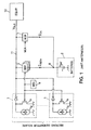
- the error amplifier may be of the proportional-integral regulator type. It is noted MEA for "Main Error Amplifier” and referenced 4. The electric potential of the power bar 11 is noted V BUS .
- the power supply system comprises two sources of power: the solar generator sections 1 on the one hand, and the battery assembly 2 on the other hand.
- the number of solar generator sections 1, as well as the capacity of the battery pack 2, is set according to an average power consumption of the equipment set 10.
- Each solar generator section 1 comprises a string DC generator 1g and a switch 1s.
- the switch 1 is adapted to send an electric current which is produced by the chain 1g to the power supply bar 11, or to inhibit an output of this current to the bar 11. In operation said day, that is to say ie when the solar generator sections 1 are illuminated by the sun, they produce an electric current which is transmitted by the power bar 11 to the equipment assembly 10.
- this current is insufficient relative to to the consumption of the equipment assembly 10, it is completed from a discharge current of the battery assembly 2, noted I DECH on the figure 1 .
- I DECH discharge current of the battery assembly 2
- the equipment assembly 10 is powered solely by the battery pack 2.
- the constant potential V BUS of the power supply bar 11 can be equal to 50 V (volts), and the average power consumption of the equipment assembly 10 can vary between 5 or 10 kW ( kilowatt).
- each BDR module 3 may comprise a voltage converter which makes it possible to transfer a quantity of current from an input of the module having an electrical input potential to an output of the module having an electrical output potential. This amount of current is determined by a control signal that is transmitted to a control input of the module.
- the input of each BDR module 3 is connected to the output point B and its output is connected to the power bar 11.
- the input potential of the modules 3 is that of the output point B of the set of battery 2, and the output potential of the modules 3 is V BUS .
- the current that is transmitted by the BDR modules 3 to the power bar 11 is then I DECH x V B / N BUS .
- the two power supply modes from the solar generator sections 1 only or both from them and from the battery pack 2, are controlled by the amplifier 4.
- the amplifier 4 compares the real electrical potential V BUS of the power bar 11 to a fixed setpoint, which is the desired supply potential.
- the error amplifier 4 reduces the average number of solar generator sections 1 which are electrically connected to the power bar 11, to prevent the potential V BUS thereof from exceeding the desired value.
- the amplifier 4 is connected to the control input of the switch 1s of each solar generator section 1, so that an average current that is transmitted by these sections can be adjusted in accordance with the control signal produced by the 'amplifier. Practically, the adjustment is achieved by intermittently controlling the transmission to the bar 11 of the current of some of the sections 1. The regulation of the potential V BUS then results from a duty cycle ratio of transmission / inhibition.
- the error amplifier 4 controls a transmission to the power bar 11 of the assembly of the current that is produced by the sections 1, and simultaneously activates the BDR modules 3. The latter then adjust the discharging current I DECH of the battery assembly 2 in order to supply the equipment assembly 10 while maintaining constant the V BUS electrical potential of the bar 11.
- the amplifier 4 is also connected to the control input of each BDR module 3, so that the discharge current of the battery pack 2 is adjusted according to the signal control that is produced by the amplifier.
- a capacitor connected between the power supply bar 11 and a reference terminal of the system can be used to reduce residual variations of the potential V BUS .
- the system further comprises at least one battery charge control module 7, BCR noted for “Battery Charge Regulator”.
- This module 7 is electrically connected between the power supply bar 11 and the output point B of the battery assembly 2. It is activated by the amplifier 4 when the solar generator sections 1 can produce a current which is greater than the consumption of the equipment assembly 10.
- the module 7 controls a charging current, denoted I CH , which flows from the bar 11, through this module 7, to the battery assembly 2.
- This charging current is adjusted according to the charge level of the battery pack 2, according to a charging characteristic that is provided by the manufacturer of this battery pack.
- the document EP 1 073 176 discloses a regulated DC voltage satellite power supply system permanently, which does not have a BCR module.
- some solar generator sections are connected on the one hand to the power bar of the equipment set, and on the other hand to the input of the battery pack via controlled switches. When one of these switches is open, so that the corresponding solar generator section is no longer connected directly to the battery assembly, this solar generator section can participate in the power supply of the equipment package. in the usual way, as described above.
- the battery pack When one of the controlled switches is closed, so as to electrically connect the corresponding solar generator section to the battery pack, the battery pack is recharged directly, without the charge current produced by the section passing through the battery bar. 'food. But in such a power system, the charging current of the battery pack can be adjusted only by varying the number of solar generator sections that are temporarily connected to the battery pack. For this reason, this charging current can not be finely adjusted with respect to the state of charge of the battery pack that has already been reached. Such a mismatch of the charging current can cause a decrease in the life of the battery pack, and thus a reduction in the operating time of a satellite equipped with this power system.
- An object of the present invention is then to avoid the disadvantages of the battery charge control module that are mentioned above, while allowing to finely adjust the charge current of the battery pack.
- the invention proposes a satellite power supply system of the above type, except that at least one of the solar generator sections and at least one of the battery discharge regulation modules are connected and / or controlled differently.
- the other solar generator sections and the other battery discharge regulator modules have implementations that are not modified.
- At least one of the solar generator sections is connected to the output point of the battery assembly, instead of the power supply bar, without the intermediary of any discharge control module. of battery.
- the current that is transmitted by this solar generator section can be transmitted directly to the battery pack to recharge the battery, without passing through the power bar.
- the solar generator section which is thus connected is therefore dedicated in priority to the charge of the battery assembly. For this reason, it is called in the following load section.
- the connections of the other solar generator sections are not changed: they are still connected to the power bar without the intermediary of any battery discharge control module.
- the power system further comprises a first additional controller which is connected to the control input of the selected module.
- This first additional regulator is adapted to transmit to the selected module a residual current adjustment signal which corresponds to an excess of the current produced by the charging section with respect to a charge setpoint of the battery pack.
- the charge setpoint can be programmed according to the charge status of the battery that has already been reached. The residual current is retransmitted to the power bar, so that it contributes to the power supply of the equipment package.
- the error amplifier is also connected to the first additional regulator to activate an operation of the latter.
- the error amplifier then operates advantageously in the same way as when it controls the operation of a battery discharge control module for a power supply system according to the figure 1 when the power that is provided by the solar generator sections is not sufficient to power the electrical power consumer equipment assembly.
- a charge of the battery pack can be made from the charging section while some of the solar generator sections other than this charging section transmit to the bar supplying a current which, together with the residual current, feeds the equipment assembly.
- the invention therefore consists in assigning one or more solar generator sections as a priority to recharging the battery pack. For this, this section, or these sections, is (are) connected directly to the output terminal of the battery pack, instead of being directly connected to the power bar.
- One or more battery discharge control modules are simultaneously dedicated to the charge of the battery pack. For this, it (s) is (are) controlled by the first additional regulator, instead of being controlled directly by the error amplifier.
- the invention reloads the battery pack without the need for a battery charge control module. For this, the adjustment of a charging current by a BCR module is replaced by the adjustment of the residual current by the selected BDR module.
- the power supply system may therefore be devoid of BCR module.
- the charging mode of the battery pack that is then obtained is called by the inventors charge by diversion.
- the invention does not require adding additional solar generator section, or additional discharge control module.
- the number of these power components is therefore constant, while having removed from the system any battery charge control module. Since the first additional regulator which is added to the supply system according to the invention is only an integrated electronic control circuit, it is light and inexpensive. The mass and the cost of the overall power supply system are therefore reduced by the invention.
- the invention proceeds by making better use of the current that is produced by the solar generator sections, when this current is greater than the consumption of the equipment package.
- the charging section (s) recharge (s) then not only the battery pack, but simultaneously produce the residual current that is used by the set. of equipment, at the same time as the current that is produced by the other sections of solar generator, the implementation of which is not modified.
- the assignment of one or more battery discharge regulator modules to the charge of the battery pack allows fine adjustment of the charging current.
- a first refinement of the invention may be provided to allow the battery pack to be recharged when the transmission to the supply bar of a residual current is not compatible with the current that is required to supply the set of batteries. 'equipment.
- This incompatibility situation corresponds to a residual current delivered by the battery discharge regulator module (s) dedicated to the charge of the battery pack according to the invention, which is greater than the current consumed. by the equipment set.
- the system may further comprise a second additional regulator which is connected to the control input of the switch (s) of the charge section (s). This second additional regulator is selected only when the diversion charge mode is not compatible with the power supply of the equipment set.
- the adjustment then consists in reducing, by modifying the duty cycle of the switch (s) of the charge section (s), the current that is transmitted by the one (s) so that the instruction load is respected.
- a second improvement of the invention is more particularly provided for a long period during which the battery pack is unused.
- the power system may further include an equinox switch that is connected between the load section (s) and the output terminal of the battery pack. This equinox switch electrically connects the load section (s) to the power bar, instead of this (these) section (s) being connected to the output terminal of the battery assembly. .
- the first and second additional regulators may be further adapted such that when the equinox switch electrically connects the charging section to the power bar and when the second additional regulator is selected after an inhibition of the first, it there is an adjustment interval of the load setpoint in which the first regulator controls a cancellation of the current which is retransmitted to the power bar by the selected discharge control module (s), and the second regulator simultaneously controls a cancellation of the current that is transmitted by the load section (s) to the power bar when this second regulator is selected after the inhibition of the first regulator.
- the first and second additional regulators may be further adapted such that when the equinox switch electrically connects the charging section to the power bar and when the second additional regulator is selected after an inhibition of the first, it there is an adjustment interval of the load setpoint in which the first regulator controls a cancellation of the current which is retransmitted to the power bar by the selected discharge control module (s), and the second regulator simultaneously controls a cancellation of the current that is transmitted by the load section (s) to the power bar when this second regulator is selected after the
- the invention also proposes a satellite which comprises a power supply system as described above. It may be, in particular, a geostationary-type satellite.
- the power supply system of the figure 2 is still of the type with regulated supply voltage permanently.
- This voltage can be arbitrary, for example 18 V, 42.5 V, 50 V or even 100 V.
- the constant electrical potential V BUS of the supply bar 11 which corresponds to this voltage is measured with respect to a reference terminal. batteries 2. Onboard a satellite, this reference terminal can be connected to the satellite's ground.
- the solar generator sections are divided into two groups as follows, according to their respective connections to the power bar 11 and, optionally, their control mode.
- a first group of solar generator sections which are called main sections and referenced 1a, is dedicated to power equipment 10 via the power bar 11. These sections 1a are connected directly to the bar 11 and controlled by the error amplifier 4 in the manner that has been described in connection with the figure 1 .
- the term "main sections 1a connected directly to the bar 11" means an electrical connection between these components which does not incorporate any battery charge / discharge control module.
- a second group of solar generator sections which are called load sections and referenced 1b, is dedicated to recharging the batteries 2.
- the charging sections 1b are connected directly to the output terminal B of the batteries 2, so that a The current that is produced by the load sections 1b is transmitted to the terminal B when the output of this current is not inhibited by the switches 1s internal to these sections.
- the inventors specify that the load sections 1b do not undergo any modification or adaptation with respect to the main sections 1a, and are distinguished from the latter only by their connection mode and their control mode within the power system.
- Load sections 1b connected directly to terminal B means an electrical connection between these components which does not incorporate any battery charge / discharge control module.
- the number of main sections 1a may be twenty-four or forty-eight, and the number of load sections 1b may be one to four.
- the load sections 1b can be connected to the terminal B via a switch 7, whose function will be explained later.
- the switch 7 electrically connects the load sections 1b to the terminal B, until indicated otherwise.
- the battery discharge control modules, or BDRs are all connected between the B terminal and the power supply bar 11, so as to conduct each a positive current flowing from the terminal B to the bar 11. According to the invention they are also divided into two groups, depending on their mode of command.
- a first group of BDR modules is dedicated to the supply of the equipment 10 from the batteries 2.
- the batteries 2 can thus supply power to the equipment 10 for the entire consumption of the latter, or in addition to a current that is provided by the solar generator sections.
- a discharge current of the batteries 2, noted I DECH then flows from the terminal B to the bar 11, through the main modules 3a.
- These modules 3a are controlled by the error amplifier 4 to maintain the constant potential V BUS , as has already been described in connection with the figure 1 .
- the power system of the invention thus has a night operation, using the main BDR modules 3a, which is identical to that of the system of the figure 1 .
- BDR modules of a second group are dedicated to the control of the recharge of batteries 2 in daytime operation.
- a control input of the secondary modules 3b is connected to an output of a first additional regulator, referenced 5 and noted REG. 1.
- This second group of BDR modules can also be used with the first group of BDR modules to power the equipment 10 from the batteries 2.
- the current I RES called residual current, is relayed by secondary modules 3b to the power bar 11. It thus participates in the supply of equipment 10, with the current that is produced by the main sections 1a.
- the regulator 5 calculates an adjustment setpoint of the current I RES as a function of a measurement of the current I 1b and of a charging current set point of the batteries, then transmits the setpoint of the current I RES to the secondary modules 3b.
- the charging current setpoint itself may depend on the state of charge of the batteries 2 which has already been reached, in which case the regulator 5 may be further connected to receive a characterization signal of this state of charge.
- the secondary modules 3b are controlled in the same way as the main modules 3a to optimize the complete system.
- the number of the main modules 3a can be twelve, and the number of secondary modules 3b which are dedicated to the charge of the batteries 2 can be from one to four.
- the load current I CH can be adjusted itself with sufficient accuracy. Optimum operation of the batteries 2 can thus be maintained over a long period.
- a current production by the load section (s) 1b can be controlled primarily with respect to a current output by the main sections 1a which would be increased. This makes it possible in particular to guarantee the state of charge of the batteries 2.
- the regulator 5 is itself activated by the amplifier 4 by means of a specific control line. In this way, the charging mode of batteries by diversion which has just been described is activated only when the set of solar generator sections 1a and 1b are sufficient to power the equipment 10.
- a second additional regulator 6, which is noted REG. 2 on the figure 2 , can be further provided to remove if necessary the current I RES which is produced by the mode of charge by diversion. This can be useful when the equipment 10 has low power and the batteries 2 are almost or fully recharged. In this case, the current I RES of the daytime operation described above could be too great compared to the consumption of the equipment 10, causing a supply overvoltage.
- the regulator 6 is authorized by the amplifier 4, and generates a control signal for the switching duty cycle of the switches 1s of the load sections 1b, so that these sections directly produce a current which complies with the charging setpoint of 2. As a consequence, the current I RES is removed. In this way, the potential V BUS of the power bar 11 is still kept constant.
- the switch 7 has an input which is connected to the load sections 1b, and two outputs which are respectively connected to the power supply bar 11 and to the output terminal B of the batteries 2.
- An external signal denoted ENOX, makes it possible to control the state of the switch 7 so that its input is brought into electrical contact with one or the other of its two outputs.
- the charging sections 1b can be connected to the terminal B for the operations of the supply system which have just been described.
- they can connect via the switch 7 directly to the power bar 11, without the intermediary of BDR modules.
- the electrical insulation that can thus be achieved between the load sections 1b and the batteries 2, is advantageous especially when the batteries are not used for a long time. It reduces a discharge of the batteries 2 via leakage currents of the power system. It is even more advantageous when the maximum electrical output potential of the batteries 2 is lower than the supply voltage V BUS .
- the solar generator sections 1a and 1b are sized to output the potential value V BUS , and the maintenance of the load sections at the potential of the output terminal B causes a reduction in their power capacity.
- the switch 7 is controlled to connect the load sections 1b to the output terminal B. Outside such periods, the switch 7 is advantageously controlled for connect the load sections 1b to the power bar 11. In this way, more available electrical power is provided by all the solar generator sections.
- the switch 7 can then be controlled to electrically connect the load sections 1b to the bar 11 during the first periods, and to the terminal B during the second periods. For this reason, the switch 7 is referred to as the "equinox switch" in this patent application. It is understood that this is only an appellation established on a particular type of use of a system according to the invention, and that the invention can be used on non-geostationary satellites, as well as on any other type of vessel with an electric power supply.
- a control conflict of the potential V BUS may occur when the switch 7 electrically connects the load sections 1b directly to the power bar 11. , the additional regulator 6 does not allow to control these sections according to the electric potential of the power bar. It is therefore not adapted to operate when the power consumption that is required by the equipment 10 is low.
- OFFSET 1 and OFFSET 2 These offsets of the regulators 5 and 6 are respectively denoted OFFSET 1 and OFFSET 2.
- the regulator 5 controls a current I RES which is not zero when the control signal which is produced by the amplifier 4 is greater than OFFSET 1
- the regulator 6 controls the effective output of the current that is produced by the load sections 1b when the control signal of the amplifier 4 is less than OFFSET 2.
- OFFSET 1 By setting OFFSET 1 to a level which is higher than that of OFFSET 2, the interval which lies between these two offsets corresponds to a setting of the load setpoint in which the secondary BDR modules 3b are blocked and the output of the current I 1b from the load sections 1b to the busbar. 11, is inhibited if the regulator 6 is selected.
- a further refinement of the invention makes it possible continuously recharge the batteries 2 when the electric potential V BUS of the power bar 11 is greater than the maximum output potential of the batteries 2.
- the batteries 2 undergo a slow discharge.
- Such a discharge may have internal causes batteries 2.
- the skilled person then speaks of self-discharge batteries 2, as opposed to external discharge causes batteries 2, such as leakage currents present in the system.
- the system may further comprise a first set of electrical resistance 8, which is connected between the power bar 11 and the output terminal B batteries 2.
- This first set of resistance 8 is adapted to continuously recharge the batteries 2 by a first current flowing through the assembly 8.
- This first current is noted I 8 on the figure 2 and circulates from the bar 11 to the output terminal B.
- the assembly 8 may have a resistance value of a few kilohms. For a geostationary satellite, it can help avoid having to recharge the battery pack for about four and a half months around the summer and winter solstices.
- a second set of electrical resistance 9 can also be connected between the supply bar 11 and the output terminal B, temporarily, again when the electric potential V BUS of the supply bar 11 is greater than the maximum output potential 2.
- the resistance assembly 9 can be connected in series with a controlled switch 9a.
- the switch 9a may have a resistance value of a few hundred ohms. A recharge of the batteries 2 can thus be performed for a limited time, without disconnecting the load sections of the power bar.
Landscapes
- Engineering & Computer Science (AREA)
- Power Engineering (AREA)
- Remote Sensing (AREA)
- Aviation & Aerospace Engineering (AREA)
- Charge And Discharge Circuits For Batteries Or The Like (AREA)
- Direct Current Feeding And Distribution (AREA)
Applications Claiming Priority (1)
| Application Number | Priority Date | Filing Date | Title |
|---|---|---|---|
| FR0760037A FR2925784B1 (fr) | 2007-12-19 | 2007-12-19 | Systeme d'alimentation electrique pour satellite. |
Publications (3)
| Publication Number | Publication Date |
|---|---|
| EP2073340A2 true EP2073340A2 (de) | 2009-06-24 |
| EP2073340A3 EP2073340A3 (de) | 2009-09-09 |
| EP2073340B1 EP2073340B1 (de) | 2015-12-02 |
Family
ID=39760902
Family Applications (1)
| Application Number | Title | Priority Date | Filing Date |
|---|---|---|---|
| EP08171660.7A Not-in-force EP2073340B1 (de) | 2007-12-19 | 2008-12-15 | Stromversorgungssystem für Satelliten |
Country Status (3)
| Country | Link |
|---|---|
| US (1) | US7999504B2 (de) |
| EP (1) | EP2073340B1 (de) |
| FR (1) | FR2925784B1 (de) |
Cited By (1)
| Publication number | Priority date | Publication date | Assignee | Title |
|---|---|---|---|---|
| CN112467820A (zh) * | 2020-10-13 | 2021-03-09 | 上海空间电源研究所 | 一种航天器电源系统及其控制方法 |
Families Citing this family (6)
| Publication number | Priority date | Publication date | Assignee | Title |
|---|---|---|---|---|
| EP2330476B1 (de) * | 2009-11-27 | 2013-07-10 | Agence Spatiale Européenne | Sequentiell schaltende Nebenschlussreglerzelle mit nicht-redundantem Gleichrichter |
| US9705587B2 (en) * | 2014-12-31 | 2017-07-11 | Echostar Technologies L.L.C. | Solar powered satellite system |
| FR3055493B1 (fr) * | 2016-08-23 | 2018-09-21 | Thales Sa | Dispositif de conversion de frequences a double oscillateur local et charge utile de satellite comprenant un tel dispositif |
| CN112803574A (zh) * | 2021-03-23 | 2021-05-14 | 中国人民解放军国防科技大学 | 一种小卫星电源多级安全保护方法及系统 |
| CN115296346B (zh) * | 2022-06-29 | 2025-02-07 | 中国空间技术研究院 | 一种动态响应优化的电源控制装置 |
| CN116552824B (zh) * | 2023-05-29 | 2025-08-01 | 上海宇航系统工程研究所 | 一种大型空间可切换双模式回转支撑装置和飞行器 |
Citations (1)
| Publication number | Priority date | Publication date | Assignee | Title |
|---|---|---|---|---|
| US6157161A (en) | 1999-07-27 | 2000-12-05 | Space Systems/Loral, Inc. | Low cost battery charging systems |
Family Cites Families (8)
| Publication number | Priority date | Publication date | Assignee | Title |
|---|---|---|---|---|
| US4313078A (en) | 1979-12-05 | 1982-01-26 | Rca Corporation | Battery charging system |
| US5394075A (en) * | 1992-12-04 | 1995-02-28 | Hughes Aircraft Company | Spacecraft bus regulation using solar panel position |
| JP3271730B2 (ja) | 1994-04-28 | 2002-04-08 | キヤノン株式会社 | 発電システムの充電制御装置 |
| US5869948A (en) * | 1997-05-05 | 1999-02-09 | Hughes Electronics Corporation | Unidirectional battery charge/discharge controller for a regulated electrical bus system with a solar current source |
| US6049190A (en) * | 1998-04-13 | 2000-04-11 | Space Systems/Loral, Inc. | Spacecraft power system |
| FR2785104B1 (fr) * | 1998-10-21 | 2000-12-29 | Matra Marconi Space France | Dispositif d'alimentation electrique a generateur solaire et batterie |
| US6509712B1 (en) * | 1999-06-24 | 2003-01-21 | David M. Landis | Voltage bus regulation circuit |
| FR2828962B1 (fr) * | 2001-08-27 | 2003-12-19 | Cit Alcatel | Dispositif de regulation d'energie electrique pour bus d'alimentation |
-
2007
- 2007-12-19 FR FR0760037A patent/FR2925784B1/fr not_active Expired - Fee Related
-
2008
- 2008-12-15 EP EP08171660.7A patent/EP2073340B1/de not_active Not-in-force
- 2008-12-19 US US12/339,819 patent/US7999504B2/en active Active
Patent Citations (2)
| Publication number | Priority date | Publication date | Assignee | Title |
|---|---|---|---|---|
| US6157161A (en) | 1999-07-27 | 2000-12-05 | Space Systems/Loral, Inc. | Low cost battery charging systems |
| EP1073176A2 (de) | 1999-07-27 | 2001-01-31 | Space Systems / Loral, Inc. | Billiges Batterieladesystem |
Cited By (1)
| Publication number | Priority date | Publication date | Assignee | Title |
|---|---|---|---|---|
| CN112467820A (zh) * | 2020-10-13 | 2021-03-09 | 上海空间电源研究所 | 一种航天器电源系统及其控制方法 |
Also Published As
| Publication number | Publication date |
|---|---|
| FR2925784B1 (fr) | 2010-01-15 |
| EP2073340A3 (de) | 2009-09-09 |
| US7999504B2 (en) | 2011-08-16 |
| EP2073340B1 (de) | 2015-12-02 |
| US20090160397A1 (en) | 2009-06-25 |
| FR2925784A1 (fr) | 2009-06-26 |
Similar Documents
| Publication | Publication Date | Title |
|---|---|---|
| EP2073340B1 (de) | Stromversorgungssystem für Satelliten | |
| EP2079148B1 (de) | Elektrischer Schaltkreis | |
| EP0734111B1 (de) | Photovoltaische Hochspannungsanlage mit individuellen Speichermitteln | |
| EP2718977B1 (de) | Vorrichtung zur erzeugung von fotovoltaikenergie mit blöcken von zellen | |
| FR2910141A1 (fr) | Systeme de generation d'energie electrique avec maximisation de la puissance | |
| EP2783443A1 (de) | Gesichertes und geregeltes kontinuierliches stromversorgungssystem mit mehreren eingängen | |
| FR2785103A1 (fr) | Dispositif de generation d'energie electrique pour bus d'alimentation | |
| FR2808630A1 (fr) | Circuit d'alimentation electrique a tension multiple pour vehicule automobile | |
| EP2237387B1 (de) | Power supply system and charging control method for electrochemical generators | |
| EP2275781B1 (de) | Energiezähler mit Stromversorgung über einen M-Bus | |
| FR2824203A1 (fr) | Convertisseur d'alimentation electrique | |
| WO2020229439A1 (fr) | Systeme et procede de charge en energie electrique de vehicules automobiles | |
| EP4237273A1 (de) | Elektrisches stromversorgungssystem | |
| FR2939248A1 (fr) | Dispositif d'alimentation electrique, et installation de commande d'un sectionneur incluant un tel dispositif | |
| EP1292001A1 (de) | Regelungsvorrichtung für einen Stromversorgungsbus | |
| FR3068530B1 (fr) | Procede de distribution d'une energie electrique issue d'une energie solaire a une pluralite de groupes d'au moins une installation electrique | |
| EP3179597B1 (de) | Verbesserte vorrichtung zur lieferung von einphasen- und dreiphasen-strom | |
| EP0085947B1 (de) | Batterieladeregler | |
| EP3407454B1 (de) | Schnittstellenvorrichtung zwischen einem allgemeinen stromnetz und einem lokalen stromnetz, die einen lokalen energieaustausch ermöglicht | |
| EP3245686A1 (de) | Akkumulatorsystem mit messung von niedrigverbrauchsspannung | |
| FR2943150A1 (fr) | Dispositif d'alimentation en courant regule et systeme d'alimentation en tension regulee et courant regule pour au moins un organe electrique connecte a un reseau d'alimentation electrique | |
| WO2020148491A1 (fr) | Module autonome pour recharger un vehicule electrique et son procede de fonctionnement | |
| FR2955433A1 (fr) | Dispositif de commande d'un dispositif d'alimentation regulee pour au moins un organe electrique connecte a un reseau d'alimentation | |
| WO2016193080A1 (fr) | Dispositif d'alimentation d'un recepteur electrique avec commutation entre deux sources de tension continue, et procede d'alimentation mettant en oeuvre un tel dispositif |
Legal Events
| Date | Code | Title | Description |
|---|---|---|---|
| PUAI | Public reference made under article 153(3) epc to a published international application that has entered the european phase |
Free format text: ORIGINAL CODE: 0009012 |
|
| AK | Designated contracting states |
Kind code of ref document: A2 Designated state(s): AT BE BG CH CY CZ DE DK EE ES FI FR GB GR HR HU IE IS IT LI LT LU LV MC MT NL NO PL PT RO SE SI SK TR |
|
| AX | Request for extension of the european patent |
Extension state: AL BA MK RS |
|
| PUAL | Search report despatched |
Free format text: ORIGINAL CODE: 0009013 |
|
| AK | Designated contracting states |
Kind code of ref document: A3 Designated state(s): AT BE BG CH CY CZ DE DK EE ES FI FR GB GR HR HU IE IS IT LI LT LU LV MC MT NL NO PL PT RO SE SI SK TR |
|
| AX | Request for extension of the european patent |
Extension state: AL BA MK RS |
|
| 17P | Request for examination filed |
Effective date: 20100223 |
|
| 17Q | First examination report despatched |
Effective date: 20100316 |
|
| AKX | Designation fees paid |
Designated state(s): AT BE BG CH CY CZ DE DK EE ES FI FR GB GR HR HU IE IS IT LI LT LU LV MC MT NL NO PL PT RO SE SI SK TR |
|
| RAP1 | Party data changed (applicant data changed or rights of an application transferred) |
Owner name: ASTRIUM SAS |
|
| RAP1 | Party data changed (applicant data changed or rights of an application transferred) |
Owner name: AIRBUS DEFENCE AND SPACE SAS |
|
| REG | Reference to a national code |
Ref country code: DE Ref legal event code: R079 Ref document number: 602008041372 Country of ref document: DE Free format text: PREVIOUS MAIN CLASS: H02J0007350000 Ipc: B64G0001420000 |
|
| GRAP | Despatch of communication of intention to grant a patent |
Free format text: ORIGINAL CODE: EPIDOSNIGR1 |
|
| RIC1 | Information provided on ipc code assigned before grant |
Ipc: H02J 7/35 20060101ALN20150902BHEP Ipc: B64G 1/42 20060101AFI20150902BHEP Ipc: B64G 1/44 20060101ALN20150902BHEP |
|
| INTG | Intention to grant announced |
Effective date: 20150917 |
|
| GRAS | Grant fee paid |
Free format text: ORIGINAL CODE: EPIDOSNIGR3 |
|
| GRAA | (expected) grant |
Free format text: ORIGINAL CODE: 0009210 |
|
| REG | Reference to a national code |
Ref country code: FR Ref legal event code: PLFP Year of fee payment: 8 |
|
| AK | Designated contracting states |
Kind code of ref document: B1 Designated state(s): AT BE BG CH CY CZ DE DK EE ES FI FR GB GR HR HU IE IS IT LI LT LU LV MC MT NL NO PL PT RO SE SI SK TR |
|
| REG | Reference to a national code |
Ref country code: GB Ref legal event code: FG4D Free format text: NOT ENGLISH |
|
| REG | Reference to a national code |
Ref country code: AT Ref legal event code: REF Ref document number: 763483 Country of ref document: AT Kind code of ref document: T Effective date: 20151215 Ref country code: CH Ref legal event code: EP |
|
| REG | Reference to a national code |
Ref country code: IE Ref legal event code: FG4D Free format text: LANGUAGE OF EP DOCUMENT: FRENCH |
|
| REG | Reference to a national code |
Ref country code: DE Ref legal event code: R096 Ref document number: 602008041372 Country of ref document: DE |
|
| REG | Reference to a national code |
Ref country code: NL Ref legal event code: MP Effective date: 20160302 |
|
| REG | Reference to a national code |
Ref country code: LT Ref legal event code: MG4D |
|
| REG | Reference to a national code |
Ref country code: AT Ref legal event code: MK05 Ref document number: 763483 Country of ref document: AT Kind code of ref document: T Effective date: 20151202 |
|
| PG25 | Lapsed in a contracting state [announced via postgrant information from national office to epo] |
Ref country code: HR Free format text: LAPSE BECAUSE OF FAILURE TO SUBMIT A TRANSLATION OF THE DESCRIPTION OR TO PAY THE FEE WITHIN THE PRESCRIBED TIME-LIMIT Effective date: 20151202 Ref country code: LT Free format text: LAPSE BECAUSE OF FAILURE TO SUBMIT A TRANSLATION OF THE DESCRIPTION OR TO PAY THE FEE WITHIN THE PRESCRIBED TIME-LIMIT Effective date: 20151202 Ref country code: ES Free format text: LAPSE BECAUSE OF FAILURE TO SUBMIT A TRANSLATION OF THE DESCRIPTION OR TO PAY THE FEE WITHIN THE PRESCRIBED TIME-LIMIT Effective date: 20151202 Ref country code: NO Free format text: LAPSE BECAUSE OF FAILURE TO SUBMIT A TRANSLATION OF THE DESCRIPTION OR TO PAY THE FEE WITHIN THE PRESCRIBED TIME-LIMIT Effective date: 20160302 |
|
| PG25 | Lapsed in a contracting state [announced via postgrant information from national office to epo] |
Ref country code: SE Free format text: LAPSE BECAUSE OF FAILURE TO SUBMIT A TRANSLATION OF THE DESCRIPTION OR TO PAY THE FEE WITHIN THE PRESCRIBED TIME-LIMIT Effective date: 20151202 Ref country code: PL Free format text: LAPSE BECAUSE OF FAILURE TO SUBMIT A TRANSLATION OF THE DESCRIPTION OR TO PAY THE FEE WITHIN THE PRESCRIBED TIME-LIMIT Effective date: 20151202 Ref country code: LV Free format text: LAPSE BECAUSE OF FAILURE TO SUBMIT A TRANSLATION OF THE DESCRIPTION OR TO PAY THE FEE WITHIN THE PRESCRIBED TIME-LIMIT Effective date: 20151202 Ref country code: GR Free format text: LAPSE BECAUSE OF FAILURE TO SUBMIT A TRANSLATION OF THE DESCRIPTION OR TO PAY THE FEE WITHIN THE PRESCRIBED TIME-LIMIT Effective date: 20160303 Ref country code: FI Free format text: LAPSE BECAUSE OF FAILURE TO SUBMIT A TRANSLATION OF THE DESCRIPTION OR TO PAY THE FEE WITHIN THE PRESCRIBED TIME-LIMIT Effective date: 20151202 Ref country code: AT Free format text: LAPSE BECAUSE OF FAILURE TO SUBMIT A TRANSLATION OF THE DESCRIPTION OR TO PAY THE FEE WITHIN THE PRESCRIBED TIME-LIMIT Effective date: 20151202 Ref country code: NL Free format text: LAPSE BECAUSE OF FAILURE TO SUBMIT A TRANSLATION OF THE DESCRIPTION OR TO PAY THE FEE WITHIN THE PRESCRIBED TIME-LIMIT Effective date: 20151202 |
|
| PG25 | Lapsed in a contracting state [announced via postgrant information from national office to epo] |
Ref country code: IS Free format text: LAPSE BECAUSE OF FAILURE TO SUBMIT A TRANSLATION OF THE DESCRIPTION OR TO PAY THE FEE WITHIN THE PRESCRIBED TIME-LIMIT Effective date: 20151202 |
|
| PG25 | Lapsed in a contracting state [announced via postgrant information from national office to epo] |
Ref country code: CZ Free format text: LAPSE BECAUSE OF FAILURE TO SUBMIT A TRANSLATION OF THE DESCRIPTION OR TO PAY THE FEE WITHIN THE PRESCRIBED TIME-LIMIT Effective date: 20151202 |
|
| REG | Reference to a national code |
Ref country code: CH Ref legal event code: PL |
|
| PG25 | Lapsed in a contracting state [announced via postgrant information from national office to epo] |
Ref country code: EE Free format text: LAPSE BECAUSE OF FAILURE TO SUBMIT A TRANSLATION OF THE DESCRIPTION OR TO PAY THE FEE WITHIN THE PRESCRIBED TIME-LIMIT Effective date: 20151202 Ref country code: PT Free format text: LAPSE BECAUSE OF FAILURE TO SUBMIT A TRANSLATION OF THE DESCRIPTION OR TO PAY THE FEE WITHIN THE PRESCRIBED TIME-LIMIT Effective date: 20160404 Ref country code: RO Free format text: LAPSE BECAUSE OF FAILURE TO SUBMIT A TRANSLATION OF THE DESCRIPTION OR TO PAY THE FEE WITHIN THE PRESCRIBED TIME-LIMIT Effective date: 20151202 Ref country code: IS Free format text: LAPSE BECAUSE OF FAILURE TO SUBMIT A TRANSLATION OF THE DESCRIPTION OR TO PAY THE FEE WITHIN THE PRESCRIBED TIME-LIMIT Effective date: 20160402 Ref country code: SK Free format text: LAPSE BECAUSE OF FAILURE TO SUBMIT A TRANSLATION OF THE DESCRIPTION OR TO PAY THE FEE WITHIN THE PRESCRIBED TIME-LIMIT Effective date: 20151202 |
|
| REG | Reference to a national code |
Ref country code: DE Ref legal event code: R097 Ref document number: 602008041372 Country of ref document: DE |
|
| REG | Reference to a national code |
Ref country code: IE Ref legal event code: MM4A |
|
| PG25 | Lapsed in a contracting state [announced via postgrant information from national office to epo] |
Ref country code: MC Free format text: LAPSE BECAUSE OF FAILURE TO SUBMIT A TRANSLATION OF THE DESCRIPTION OR TO PAY THE FEE WITHIN THE PRESCRIBED TIME-LIMIT Effective date: 20151202 |
|
| PLBE | No opposition filed within time limit |
Free format text: ORIGINAL CODE: 0009261 |
|
| STAA | Information on the status of an ep patent application or granted ep patent |
Free format text: STATUS: NO OPPOSITION FILED WITHIN TIME LIMIT |
|
| PG25 | Lapsed in a contracting state [announced via postgrant information from national office to epo] |
Ref country code: IE Free format text: LAPSE BECAUSE OF NON-PAYMENT OF DUE FEES Effective date: 20151215 Ref country code: DK Free format text: LAPSE BECAUSE OF FAILURE TO SUBMIT A TRANSLATION OF THE DESCRIPTION OR TO PAY THE FEE WITHIN THE PRESCRIBED TIME-LIMIT Effective date: 20151202 Ref country code: CH Free format text: LAPSE BECAUSE OF NON-PAYMENT OF DUE FEES Effective date: 20151231 Ref country code: LI Free format text: LAPSE BECAUSE OF NON-PAYMENT OF DUE FEES Effective date: 20151231 |
|
| 26N | No opposition filed |
Effective date: 20160905 |
|
| PG25 | Lapsed in a contracting state [announced via postgrant information from national office to epo] |
Ref country code: SI Free format text: LAPSE BECAUSE OF FAILURE TO SUBMIT A TRANSLATION OF THE DESCRIPTION OR TO PAY THE FEE WITHIN THE PRESCRIBED TIME-LIMIT Effective date: 20151202 |
|
| REG | Reference to a national code |
Ref country code: FR Ref legal event code: PLFP Year of fee payment: 9 |
|
| PG25 | Lapsed in a contracting state [announced via postgrant information from national office to epo] |
Ref country code: HU Free format text: LAPSE BECAUSE OF FAILURE TO SUBMIT A TRANSLATION OF THE DESCRIPTION OR TO PAY THE FEE WITHIN THE PRESCRIBED TIME-LIMIT; INVALID AB INITIO Effective date: 20081215 Ref country code: BG Free format text: LAPSE BECAUSE OF FAILURE TO SUBMIT A TRANSLATION OF THE DESCRIPTION OR TO PAY THE FEE WITHIN THE PRESCRIBED TIME-LIMIT Effective date: 20151202 |
|
| PG25 | Lapsed in a contracting state [announced via postgrant information from national office to epo] |
Ref country code: CY Free format text: LAPSE BECAUSE OF FAILURE TO SUBMIT A TRANSLATION OF THE DESCRIPTION OR TO PAY THE FEE WITHIN THE PRESCRIBED TIME-LIMIT Effective date: 20151202 |
|
| PG25 | Lapsed in a contracting state [announced via postgrant information from national office to epo] |
Ref country code: MT Free format text: LAPSE BECAUSE OF FAILURE TO SUBMIT A TRANSLATION OF THE DESCRIPTION OR TO PAY THE FEE WITHIN THE PRESCRIBED TIME-LIMIT Effective date: 20151202 Ref country code: TR Free format text: LAPSE BECAUSE OF FAILURE TO SUBMIT A TRANSLATION OF THE DESCRIPTION OR TO PAY THE FEE WITHIN THE PRESCRIBED TIME-LIMIT Effective date: 20151202 |
|
| PG25 | Lapsed in a contracting state [announced via postgrant information from national office to epo] |
Ref country code: LU Free format text: LAPSE BECAUSE OF NON-PAYMENT OF DUE FEES Effective date: 20151215 |
|
| REG | Reference to a national code |
Ref country code: FR Ref legal event code: PLFP Year of fee payment: 10 |
|
| PGFP | Annual fee paid to national office [announced via postgrant information from national office to epo] |
Ref country code: GB Payment date: 20231220 Year of fee payment: 16 |
|
| PGFP | Annual fee paid to national office [announced via postgrant information from national office to epo] |
Ref country code: IT Payment date: 20231228 Year of fee payment: 16 Ref country code: FR Payment date: 20231221 Year of fee payment: 16 Ref country code: DE Payment date: 20231214 Year of fee payment: 16 |
|
| PGFP | Annual fee paid to national office [announced via postgrant information from national office to epo] |
Ref country code: BE Payment date: 20231220 Year of fee payment: 16 |
|
| REG | Reference to a national code |
Ref country code: DE Ref legal event code: R119 Ref document number: 602008041372 Country of ref document: DE |
|
| GBPC | Gb: european patent ceased through non-payment of renewal fee |
Effective date: 20241215 |
|
| REG | Reference to a national code |
Ref country code: BE Ref legal event code: MM Effective date: 20241231 |
|
| PG25 | Lapsed in a contracting state [announced via postgrant information from national office to epo] |
Ref country code: DE Free format text: LAPSE BECAUSE OF NON-PAYMENT OF DUE FEES Effective date: 20250701 |
|
| PG25 | Lapsed in a contracting state [announced via postgrant information from national office to epo] |
Ref country code: IT Free format text: LAPSE BECAUSE OF NON-PAYMENT OF DUE FEES Effective date: 20241215 |
|
| PG25 | Lapsed in a contracting state [announced via postgrant information from national office to epo] |
Ref country code: GB Free format text: LAPSE BECAUSE OF NON-PAYMENT OF DUE FEES Effective date: 20241215 Ref country code: BE Free format text: LAPSE BECAUSE OF NON-PAYMENT OF DUE FEES Effective date: 20241231 |
|
| PG25 | Lapsed in a contracting state [announced via postgrant information from national office to epo] |
Ref country code: FR Free format text: LAPSE BECAUSE OF NON-PAYMENT OF DUE FEES Effective date: 20241231 |