EP2073347A2 - Moteur électrique - Google Patents
Moteur électrique Download PDFInfo
- Publication number
- EP2073347A2 EP2073347A2 EP08022027A EP08022027A EP2073347A2 EP 2073347 A2 EP2073347 A2 EP 2073347A2 EP 08022027 A EP08022027 A EP 08022027A EP 08022027 A EP08022027 A EP 08022027A EP 2073347 A2 EP2073347 A2 EP 2073347A2
- Authority
- EP
- European Patent Office
- Prior art keywords
- electric motor
- return body
- media line
- motor according
- media
- Prior art date
- Legal status (The legal status is an assumption and is not a legal conclusion. Google has not performed a legal analysis and makes no representation as to the accuracy of the status listed.)
- Withdrawn
Links
Images


Classifications
-
- H—ELECTRICITY
- H02—GENERATION; CONVERSION OR DISTRIBUTION OF ELECTRIC POWER
- H02K—DYNAMO-ELECTRIC MACHINES
- H02K7/00—Arrangements for handling mechanical energy structurally associated with dynamo-electric machines, e.g. structural association with mechanical driving motors or auxiliary dynamo-electric machines
- H02K7/14—Structural association with mechanical loads, e.g. with hand-held machine tools or fans
- H02K7/145—Hand-held machine tool
-
- H—ELECTRICITY
- H02—GENERATION; CONVERSION OR DISTRIBUTION OF ELECTRIC POWER
- H02K—DYNAMO-ELECTRIC MACHINES
- H02K1/00—Details of the magnetic circuit
- H02K1/06—Details of the magnetic circuit characterised by the shape, form or construction
- H02K1/12—Stationary parts of the magnetic circuit
- H02K1/20—Stationary parts of the magnetic circuit with channels or ducts for flow of cooling medium
-
- H—ELECTRICITY
- H02—GENERATION; CONVERSION OR DISTRIBUTION OF ELECTRIC POWER
- H02K—DYNAMO-ELECTRIC MACHINES
- H02K11/00—Structural association of dynamo-electric machines with electric components or with devices for shielding, monitoring or protection
- H02K11/0094—Structural association with other electrical or electronic devices
-
- H—ELECTRICITY
- H02—GENERATION; CONVERSION OR DISTRIBUTION OF ELECTRIC POWER
- H02K—DYNAMO-ELECTRIC MACHINES
- H02K3/00—Details of windings
- H02K3/46—Fastening of windings on the stator or rotor structure
- H02K3/47—Air-gap windings, i.e. iron-free windings
-
- A—HUMAN NECESSITIES
- A61—MEDICAL OR VETERINARY SCIENCE; HYGIENE
- A61C—DENTISTRY; APPARATUS OR METHODS FOR ORAL OR DENTAL HYGIENE
- A61C1/00—Dental machines for boring or cutting ; General features of dental machines or apparatus, e.g. hand-piece design
- A61C1/02—Dental machines for boring or cutting ; General features of dental machines or apparatus, e.g. hand-piece design characterised by the drive of the dental tools
- A61C1/06—Dental machines for boring or cutting ; General features of dental machines or apparatus, e.g. hand-piece design characterised by the drive of the dental tools with electric drive
-
- H—ELECTRICITY
- H02—GENERATION; CONVERSION OR DISTRIBUTION OF ELECTRIC POWER
- H02K—DYNAMO-ELECTRIC MACHINES
- H02K5/00—Casings; Enclosures; Supports
- H02K5/04—Casings or enclosures characterised by the shape, form or construction thereof
- H02K5/22—Auxiliary parts of casings not covered by groups H02K5/06-H02K5/20, e.g. shaped to form connection boxes or terminal boxes
- H02K5/225—Terminal boxes or connection arrangements
Definitions
- the invention relates to an electric motor, comprising a rotatably mounted rotor on a rotor shaft and a stator surrounding the rotor, wherein the stator has a return body and a current acted upon winding and the electric motor has at least one media line.
- Generic electric motors are used for example for the drive of rotating, dental or medical instruments.
- the rotating instruments such as drills or the like are attached via a standard coupling to the electric motor.
- the dental instrument is to be supplied during use with different supply media via one or more media lines.
- the media lines have a certain diameter and are to be integrated in the engine area, with known dental instruments such as handheld devices should not exceed certain external dimensions, so as not to affect the usability and manageability.
- the electric motor has to provide sufficient torque and speed.
- the invention is based on an electric motor as described above and proposes that the return body receives at least one passage for the at least partial formation or recording of the media line or media lines for performing one or more media.
- the return body which anyway is present due to the functioning of the electric motor, is now additionally used to receive the media line (s) for the passage of the media through the engine.
- This integration of the media lines / s in the return body is for the arrangement of the media line / s no additional space required, the influences of the media line / s on the magnetic properties are also negligible in clever arrangement of the media / en s, which leads to almost unchanged characteristics of the electric motor according to the invention.
- this also means that the space obtained by the integration of the media line in the return body can be added to the stator or the winding on the stator and so the electric motor according to the invention with a constant outside dimensions of the article according to the invention in comparison with the object of the prior art Improvement of its characteristics learns.
- the invention comprises, as already mentioned, both an embodiment in which the implementation in the return body receives one or more media lines, as well as the variant in which the implementation forms the media line.
- the implementation in the return body is preferably provided as a hose-like channel, as a tunnel or as a bore for forming or receiving the media line / s.
- the invention proposes that the media line (s) support and / or operate the elements driven by the electric motor, such as e.g. of tools or a spindle.
- the electric motor such as e.g. of tools or a spindle.
- This now makes it possible, space-saving, for example, when used as a dental motor, to provide the tools required for the tool media, such as cooling air, rinse water, which is under high pressure, while making the drive of the tool.
- the embodiment according to the invention therefore offers the possibility of offering a very space-saving solution which is far superior in terms of ease of use to the solutions known in the prior art.
- the known from the prior art solutions that deal exclusively with the cooling of the electric motor or its stator or rotor are not suitable for the purpose as described above.
- the invention provides a very elegant solution which elegantly solves all problems known in the art.
- an embodiment of the invention is characterized in that the media lines are guided by the side facing away from the drive side of the electric motor to the drive side facing by the electric motor.
- the media lines are guided by the side facing away from the drive side of the electric motor to the drive side facing by the electric motor.
- the variant described first is preferred.
- the invention is also characterized by the fact that the media lines are provided as units spatially separated from the engine. This makes it possible to feed one or more media through the engine, without burdening it or without significantly reducing its performance. This has already been described earlier.
- the media line in the electric motor is relatively far outside. This is advantageous since it is then possible to dispense with bends or offsets of the media line (s) in the further course since the media line (s), for example gas, air, water and so on are often used or available at a certain distance from the processing point to deliver. On the one hand, this facilitates the manufacture of the electric motor according to the invention or of the dental tool or instrument driven therewith and, on the other hand, also improves the flow properties.
- the media guide in the stator return plate allows a small air gap between rotor and stator and thus a high magnetic flux in the magnetic circuit.
- a hose-like channel, a tunnel or a bore for forming or receiving the media line is provided in the return body.
- the return body is constructed, for example, sleeve-like and has a bore which forms the media line. But a same type of media line is also formed when the return body is formed of a plurality of identically formed backwash discs, which have an opening or an opening at a predetermined position. If these discs are stacked on top of each other, the respective openings come to lie in the same position and thus also form a channel, more precisely a tube-like channel or tunnel, as in the case of a bore.
- a hose-like, all-sided closed channel as a media line and deliberately in the return body to form a groove or throat as a media line.
- an outer sleeve slipped over or inserted an inner tube, so as to obtain a sealed media line.
- the term "media line" is to be interpreted very broadly according to the invention.
- the invention provides that the introduced into the return body bore or hose-like channel or tunnel itself forms the media line, so for example as a pipe, and thus serves as part of the pipe system for gases or water or other liquids and so on.
- the hose-like channel, tunnel or bore can also be used to accommodate another media line, for example a power cable, data line (for example from sensors) or a fiber-optic cable. The chosen wording covers both cases.
- the electric motors according to the invention are of course also equipped with mixed shaping of the design of the media line alternatively.
- the invention comprises both electric motors, the only with a media line, as well Electric motors equipped with several media lines. Even if above and below often only spoken by a media line, so these statements are of course also in the same way to the arrangements with multiple media lines.
- the media line is arranged obliquely in the return body, with respect to the axis of rotation of the rotary shaft.
- Such an orientation as well as a likewise alternatively provided arrangement of the media line in the return body on a spiral or helical path leads to improve the magnetic behavior of the return body or of the entire electric motor.
- the incorporation of the media line as material weakening or by material removal in the magnetic return body leads to a corresponding impairment of the magnetic properties.
- Cogging moments are formed on the electric motor due to the different magnetic properties of the return body. But now that the arrangement of the magnetic properties affecting media line changed in the axial direction, the negative effect of the cogging moments is mitigated or no longer appears.
- the media line is laid in the return body along a direction which deviates from the parallels to the axis of rotation of the rotor shaft.
- this may be an arrangement running obliquely thereto or, on the other hand, a helical or helical path, which then, for example, passes through the return body in a helical manner.
- a helical path differs from a helical path by the changing diameter of the helical path with respect to the constant diameter of the helical path.
- a cogging moment is well suppressive variants but of course also an electric motor, in which the media line / s is arranged parallel to the axis of rotation of the rotor shaft, according to the invention. If, for example, the electric motor is only penetrated by one or a few media lines, no disturbing cogging torques may form during operation.
- the return body has a certain wall thickness and is often formed like a cylinder or sleeve.
- the media line is arranged centrally and surrounded on all sides by the material of the return body.
- the media line is arranged in the edge region of the return body on the inside or outside.
- the invention nevertheless includes solutions in which a bore or a tubular media line is provided in the edge region or a nut or throat-like configuration is selected. This depends on the resulting desired magnetic properties on the one hand, but also on the purpose of the media line on the other hand. For example, the insertion of an optical fiber as a means of illumination or the insertion of an electrical cable into a groove or throat is easier than passing through a hole or tunnel several centimeters long. Accordingly, the assembly is facilitated.
- a bore or a hose-like design of the media line from the outset a dense arrangement, which is desired for example for the conduction of gases or liquids.
- the return body is designed as a sleeve.
- This sleeve is integrally formed, for example, as a rotating part and has, for example, an axially extending bore or, on the surface (inner or outer surface) coiled or inclined, a groove.
- the return body in addition to the one-piece design of the return body as a sleeve, it is also provided in a further development according to the invention, which consists of the return body of several combined sleeve segments.
- the sleeve segments are optionally identical or different again.
- the sleeve segments touch each other at their respective end faces and are suitably connectable to each other.
- the arrangement of sleeve segments has advantages in particular for the incorporation of the media lines, since these can be realized, for example, at the end faces, for example by milling out the end face.
- the return body consists of a multiplicity of rear disks arranged side by side in the axial direction.
- a multiplicity of essentially identically shaped backwash disks are put together in a packet-like manner and, at their respective circumferential position, have corresponding breaks or perforations or openings in a predefined manner in order to bring about or receive the media line (s). There are thus formed corresponding grooves or tunnels over the entire length of the return body.
- the electric motor according to the invention is preferably designed as a DC motor, in particular for the application of a drive for dental instruments, the electric motor according to the invention is designed as a brushless DC motor.
- the media line / s for the transport of gases such as air, compressed air, cooling air, cleaning gases, liquids, water, liquid gas mixtures, spray water, cooling water, electricity or light is used.
- gases such as air, compressed air, cooling air, cleaning gases, liquids, water, liquid gas mixtures, spray water, cooling water, electricity or light.
- the media line (groove, tunnel and so on) receives these optical fibers.
- the invention not only includes an electric motor as described above, but also relates to a medical or dental tool which is driven by such an electric motor. It should be noted that this application is only one of many cases in which the electric motor according to the invention can be used. In this respect, the design of the electric motor is not bound to certain size specifications.
- the electric motor can also be used in machines that are significantly larger than a hand-held medical or dental tool.
- the invention also includes tool motor spindles, in which an electric motor as described is used as a direct drive and z. B. Coolant is passed to the processing tool.
- Medical or dental tools often have a coupling to which various medical or dental instruments or devices can be coupled. As a result, the application of such a tool is considerably increased. Often, such tools require the use of appropriate media which are to be brought in via media lines.
- Fig. 1 a part of the electric motor according to the invention is shown in a three-dimensional view. Not shown are the moving, because rotating parts of the electric motor.
- the drive parts of the electric motor are arranged in a motor housing, wherein with the housing, a coupling piece is connected, on which a to be driven by the electric motor dental or medical Instrument or device can be plugged.
- the coupler is often a standard coupling to achieve interchangeability with other systems.
- the electric motor 1 has a rotor shaft mounted in the motor or motor housing, for this purpose corresponding motor bearings are provided in a known manner.
- the rotor (not shown) is surrounded by the stator 2.
- the stator 2 consists of a return body 3 and a current acted upon winding 4.
- the rotor has a permanent magnet which begins to rotate due to the magnetic field building up in the winding 4.
- the permanent magnet of the rotor is designed as a bipolar, diametrically oriented rotor magnet.
- the return body 3, which often consists of soft magnetic material, serves to effectively guide the magnetic field generated by the current-applied winding 4.
- the winding 4 is provided on the inner side 33 of the return body 3.
- a protective layer or protective sleeve 40 is provided, which is arranged between the winding 4 and the rotor (not shown).
- This e.g. formed as a protective sheath protective sleeve 40 may be, for example, an encapsulation of the winding 4.
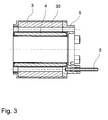
- media lines 5 project parallel to the longitudinal extent of the electric motor 1. These media lines 5 serve, for example, to conduct gases, air, water, liquids, electricity, light and so on.
- the return body 3, the media lines 5 receives.
- a (not shown) axis of rotation of the rotor shaft extending bore or passage formed as a tunnel 30 is provided in which / m, the media line 5 extends.
- media management is to be understood very comprehensively.
- a media line is understood to be a separate, closed system for conducting the medium, as provided for example in an electrical cable, which has a correspondingly insulating sheath.
- the term “media line” 5 can also be designed so that the trained as a tunnel bushing 30 or the bore or the channel or the grooves 31, 32 themselves are part of the media line 5, especially if this part of a pipe system for water , Liquids, gas and so on.
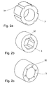
- Fig. 2a an alternative embodiment of the return body 3 is shown. It consists here of provided on the outside of the sleeve-like yoke body 3 grooves 31st
- Fig. 2b the media line 5 is provided in grooves 32 provided on the inside. It is clear that a multiplicity of media lines can be laid here, since a multiplicity of grooves are also arranged.
- FIG. 2c shown embodiment of the return body. 3 corresponds to the in Fig. 1 built-in return body 3.
- the inference body 3 shown in the embodiments are sleeve-like or cylinder-like, without wishing to limit the invention in any way. They may be made in one piece or consist of different sleeve segments or consist of a variety of assembled to a package backwash discs, which are similar or identical among themselves.
- the design of the return body 3 is not bound to a cylindrical configuration, in particular the outer contour of the return body can be formed oval or rectangular.
- a sleeve-like casing 10 is provided, which either has a protective function for the electric motor or may also be part of the motor housing.
Landscapes
- Engineering & Computer Science (AREA)
- Power Engineering (AREA)
- Connection Of Motors, Electrical Generators, Mechanical Devices, And The Like (AREA)
- Iron Core Of Rotating Electric Machines (AREA)
- Motor Or Generator Frames (AREA)
- Dental Tools And Instruments Or Auxiliary Dental Instruments (AREA)
Applications Claiming Priority (1)
| Application Number | Priority Date | Filing Date | Title |
|---|---|---|---|
| DE102007062541A DE102007062541A1 (de) | 2007-12-20 | 2007-12-20 | Elektromotor |
Publications (2)
| Publication Number | Publication Date |
|---|---|
| EP2073347A2 true EP2073347A2 (fr) | 2009-06-24 |
| EP2073347A3 EP2073347A3 (fr) | 2015-08-05 |
Family
ID=40409893
Family Applications (1)
| Application Number | Title | Priority Date | Filing Date |
|---|---|---|---|
| EP08022027.0A Withdrawn EP2073347A3 (fr) | 2007-12-20 | 2008-12-18 | Moteur électrique |
Country Status (4)
| Country | Link |
|---|---|
| US (1) | US8110960B2 (fr) |
| EP (1) | EP2073347A3 (fr) |
| JP (1) | JP2009153376A (fr) |
| DE (1) | DE102007062541A1 (fr) |
Families Citing this family (14)
| Publication number | Priority date | Publication date | Assignee | Title |
|---|---|---|---|---|
| US8643233B2 (en) * | 2008-07-28 | 2014-02-04 | Tm4 Inc. | Multi-path liquid cooling arrangement for electric machines |
| ES2391440T3 (es) | 2009-11-23 | 2012-11-26 | Abb Oy | Estator y método de ensamblaje |
| CN102244434B (zh) * | 2010-05-11 | 2016-04-06 | 德昌电机(深圳)有限公司 | 电机组件 |
| CN102068315B (zh) * | 2011-01-06 | 2014-04-30 | 中国航空工业集团公司西安飞行自动控制研究所 | 一种牙科治疗电动马达 |
| US20120318479A1 (en) * | 2011-06-14 | 2012-12-20 | Fukuta Electric & Machinery Co., Ltd. | Liquid cooled motor assembly and cover thereof |
| DE102011082353B4 (de) * | 2011-09-08 | 2021-04-01 | Siemens Aktiengesellschaft | Stator für einen Elektromotor |
| US8901790B2 (en) * | 2012-01-03 | 2014-12-02 | General Electric Company | Cooling of stator core flange |
| JP5527910B2 (ja) * | 2012-09-24 | 2014-06-25 | 株式会社ナカニシ | 歯科用ハンドピースの駆動モータおよび歯科治療システム |
| CN104918575B (zh) * | 2012-12-05 | 2018-10-23 | 麦克罗-Nx株式会社 | 具有直冷式轻型驱动部的手持件 |
| DE102013208746A1 (de) * | 2013-05-13 | 2014-11-13 | Robert Bosch Gmbh | Stator für eine elektrische Maschine, der sich konzentrisch um eine Mittelachse erstreckt und Verfahren zur Herstellung einer solchen |
| JP6244466B2 (ja) * | 2014-07-31 | 2017-12-06 | 株式会社ナカニシ | 電気モータおよび歯科装置 |
| WO2020060790A1 (fr) * | 2018-09-17 | 2020-03-26 | Covidien Lp | Systèmes robotisés chirurgicaux |
| DE102020119635A1 (de) | 2020-07-24 | 2022-01-27 | Sycotec Gmbh & Co. Kg | Elektromotor für dentale und medizinische Zwecke |
| CN114172307A (zh) * | 2020-09-11 | 2022-03-11 | 法雷奥动力总成(上海)有限公司 | 旋转电机、动力传动系统和电动车 |
Family Cites Families (14)
| Publication number | Priority date | Publication date | Assignee | Title |
|---|---|---|---|---|
| DE2613061C3 (de) * | 1976-03-26 | 1984-06-14 | Siemens AG, 1000 Berlin und 8000 München | Antriebsmotor für ein zahnärztliches Hand- und Winkelstück |
| DE3237650A1 (de) * | 1981-10-12 | 1983-05-11 | Kabushiki Kaisha Morita Seisakusho, Kyoto | Mikromotor mit eingebauten kuehlmittelleitungen |
| US5365132A (en) * | 1993-05-27 | 1994-11-15 | General Electric Company | Lamination for a dynamoelectric machine with improved cooling capacity |
| DE19604628A1 (de) * | 1996-02-08 | 1997-08-14 | Kaltenbach & Voigt | Gleichstrommotor zum Antrieb eines dentalen Instrumentes |
| DE19640020A1 (de) * | 1996-09-27 | 1998-04-02 | Heribert Schmid | Elektromotor |
| DE29717128U1 (de) * | 1997-09-25 | 1997-11-20 | System Antriebstechnik Dresden GmbH, 01257 Dresden | Gehäuselose Drehstrommaschine mit achsparallelen Kühlmittelrohren im Ständerblechpaket |
| DE19757605C2 (de) * | 1997-12-23 | 2003-03-13 | Siemens Ag | Elektromotor mit Kühlung |
| DE19843951C2 (de) * | 1998-05-26 | 2002-03-14 | Kaltenbach & Voigt | Antriebssystem für zahnärztliche Handstücke |
| US7211919B2 (en) * | 1999-08-16 | 2007-05-01 | American Superconductor Corporation | Thermally-conductive stator support structure |
| ITBO20010051A1 (it) * | 2001-01-31 | 2002-07-31 | Castellini Spa | Manipolo odontoiatrico, in particolare per riuniti dentali |
| US6819016B2 (en) * | 2002-07-18 | 2004-11-16 | Tm4 Inc. | Liquid cooling arrangement for electric machines |
| CN1833345B (zh) * | 2003-07-10 | 2010-11-03 | 磁应用股份有限公司 | 紧凑的大功率交流发电机 |
| US6960851B2 (en) * | 2003-12-02 | 2005-11-01 | Tm4 Inc. | Cooling device including a biasing element |
| DE102006005316B4 (de) * | 2006-02-06 | 2020-03-26 | Siemens Aktiengesellschaft | Kühleinrichtung für eine elektrische Maschine, elektrische Maschinen mit einer solchen Kühleinrichtung, Dynamoblech sowie Herstellungsverfahren für solche elektrischen Maschinen |
-
2007
- 2007-12-20 DE DE102007062541A patent/DE102007062541A1/de not_active Withdrawn
-
2008
- 2008-12-17 US US12/314,820 patent/US8110960B2/en not_active Expired - Fee Related
- 2008-12-18 EP EP08022027.0A patent/EP2073347A3/fr not_active Withdrawn
- 2008-12-22 JP JP2008326309A patent/JP2009153376A/ja active Pending
Also Published As
| Publication number | Publication date |
|---|---|
| US8110960B2 (en) | 2012-02-07 |
| DE102007062541A1 (de) | 2009-06-25 |
| EP2073347A3 (fr) | 2015-08-05 |
| JP2009153376A (ja) | 2009-07-09 |
| US20090160269A1 (en) | 2009-06-25 |
Similar Documents
| Publication | Publication Date | Title |
|---|---|---|
| DE102007062541A1 (de) | Elektromotor | |
| DE4238564C2 (de) | Elektrowerkzeug | |
| DE102009001173B4 (de) | Bürstenloser Motor | |
| DE2834099C2 (de) | Permanentmagnetisch erregter Gleichstrom-Kleinstmotor zum Antrieb eines ankuppelbaren zahnärztlichen Handinstrumentes | |
| WO1994006196A1 (fr) | Moteur electrique | |
| DE10033577A1 (de) | Bürstenloser Motor und einen derartigen Motors verwendendes medizinisches Handstück | |
| EP0660492B1 (fr) | Système de refroidissement d'un moteur | |
| DE3928985A1 (de) | Werkstueckspindel-anordnung fuer eine drehmaschine | |
| EP2073359A1 (fr) | Moteur tube | |
| DE2613061A1 (de) | Antriebsmotor fuer ein zahnaerztliches hand- und winkelstueck | |
| EP0888091B2 (fr) | Piece a main dentaire | |
| EP2073349B1 (fr) | Moteur électrique avec conduites de fluide traversant le stator | |
| DE2203586A1 (de) | Lagerung eines ein spinnorgan direkt antreibenden elektromotors | |
| DE3237650A1 (de) | Mikromotor mit eingebauten kuehlmittelleitungen | |
| WO2002035690A1 (fr) | Moteur lineaire | |
| EP1045505A2 (fr) | Moteur électrique, à rotor en forme de disque, refroidi | |
| DE19820464A1 (de) | Elektrischer Schwenkmotor, insbesondere für eine Textilmaschine | |
| EP0788779B1 (fr) | Moteur à courant continu pour l'entraínement d'un instrument dentaire | |
| EP2295621B1 (fr) | Broche à friction motorisée | |
| WO2009049807A1 (fr) | Moteur électrique à utiliser dans un outil à main en médecine dentaire, chirurgie dentaire ou technique dentaire | |
| DE20016420U1 (de) | Vorrichtung zum Aufwickeln von Stranggut | |
| EP1753113B1 (fr) | Enrobage de stator | |
| WO2008107402A2 (fr) | Machine électrique rotative | |
| DE10225221B4 (de) | Belüftung eines Ringmotors für eine Rohrmühle | |
| EP0431244A1 (fr) | Toronneuse pour le câblage continu de câbles et lignes électriques |
Legal Events
| Date | Code | Title | Description |
|---|---|---|---|
| PUAI | Public reference made under article 153(3) epc to a published international application that has entered the european phase |
Free format text: ORIGINAL CODE: 0009012 |
|
| AK | Designated contracting states |
Kind code of ref document: A2 Designated state(s): AT BE BG CH CY CZ DE DK EE ES FI FR GB GR HR HU IE IS IT LI LT LU LV MC MT NL NO PL PT RO SE SI SK TR |
|
| AX | Request for extension of the european patent |
Extension state: AL BA MK RS |
|
| PUAL | Search report despatched |
Free format text: ORIGINAL CODE: 0009013 |
|
| AK | Designated contracting states |
Kind code of ref document: A3 Designated state(s): AT BE BG CH CY CZ DE DK EE ES FI FR GB GR HR HU IE IS IT LI LT LU LV MC MT NL NO PL PT RO SE SI SK TR |
|
| AX | Request for extension of the european patent |
Extension state: AL BA MK RS |
|
| RIC1 | Information provided on ipc code assigned before grant |
Ipc: H02K 7/14 20060101ALI20150630BHEP Ipc: H02K 5/22 20060101ALN20150630BHEP Ipc: H02K 11/00 20060101ALN20150630BHEP Ipc: A61C 17/28 20060101ALI20150630BHEP Ipc: H02K 1/20 20060101AFI20150630BHEP Ipc: H02K 3/47 20060101ALI20150630BHEP Ipc: A61C 1/06 20060101ALI20150630BHEP |
|
| AKY | No designation fees paid | ||
| AXX | Extension fees paid |
Extension state: AL Extension state: BA Extension state: MK Extension state: RS |
|
| REG | Reference to a national code |
Ref country code: DE Ref legal event code: R108 |
|
| STAA | Information on the status of an ep patent application or granted ep patent |
Free format text: STATUS: THE APPLICATION IS DEEMED TO BE WITHDRAWN |
|
| 18D | Application deemed to be withdrawn |
Effective date: 20160206 |