EP2073350A1 - Moteur de compresseur et compresseur - Google Patents
Moteur de compresseur et compresseur Download PDFInfo
- Publication number
- EP2073350A1 EP2073350A1 EP07829432A EP07829432A EP2073350A1 EP 2073350 A1 EP2073350 A1 EP 2073350A1 EP 07829432 A EP07829432 A EP 07829432A EP 07829432 A EP07829432 A EP 07829432A EP 2073350 A1 EP2073350 A1 EP 2073350A1
- Authority
- EP
- European Patent Office
- Prior art keywords
- rotor
- compressor
- rotor core
- motor
- magnets
- Prior art date
- Legal status (The legal status is an assumption and is not a legal conclusion. Google has not performed a legal analysis and makes no representation as to the accuracy of the status listed.)
- Granted
Links
Images



Classifications
-
- F—MECHANICAL ENGINEERING; LIGHTING; HEATING; WEAPONS; BLASTING
- F04—POSITIVE - DISPLACEMENT MACHINES FOR LIQUIDS; PUMPS FOR LIQUIDS OR ELASTIC FLUIDS
- F04C—ROTARY-PISTON, OR OSCILLATING-PISTON, POSITIVE-DISPLACEMENT MACHINES FOR LIQUIDS; ROTARY-PISTON, OR OSCILLATING-PISTON, POSITIVE-DISPLACEMENT PUMPS
- F04C23/00—Combinations of two or more pumps, each being of rotary-piston or oscillating-piston type, specially adapted for elastic fluids; Pumping installations specially adapted for elastic fluids; Multi-stage pumps specially adapted for elastic fluids
- F04C23/008—Hermetic pumps
-
- F—MECHANICAL ENGINEERING; LIGHTING; HEATING; WEAPONS; BLASTING
- F04—POSITIVE - DISPLACEMENT MACHINES FOR LIQUIDS; PUMPS FOR LIQUIDS OR ELASTIC FLUIDS
- F04B—POSITIVE-DISPLACEMENT MACHINES FOR LIQUIDS; PUMPS
- F04B35/00—Piston pumps specially adapted for elastic fluids and characterised by the driving means to their working members, or by combination with, or adaptation to, specific driving engines or motors, not otherwise provided for
- F04B35/04—Piston pumps specially adapted for elastic fluids and characterised by the driving means to their working members, or by combination with, or adaptation to, specific driving engines or motors, not otherwise provided for the means being electric
-
- F—MECHANICAL ENGINEERING; LIGHTING; HEATING; WEAPONS; BLASTING
- F04—POSITIVE - DISPLACEMENT MACHINES FOR LIQUIDS; PUMPS FOR LIQUIDS OR ELASTIC FLUIDS
- F04C—ROTARY-PISTON, OR OSCILLATING-PISTON, POSITIVE-DISPLACEMENT MACHINES FOR LIQUIDS; ROTARY-PISTON, OR OSCILLATING-PISTON, POSITIVE-DISPLACEMENT PUMPS
- F04C18/00—Rotary-piston pumps specially adapted for elastic fluids
- F04C18/30—Rotary-piston pumps specially adapted for elastic fluids having the characteristics covered by two or more of groups F04C18/02, F04C18/08, F04C18/22, F04C18/24, F04C18/48, or having the characteristics covered by one of these groups together with some other type of movement between co-operating members
- F04C18/32—Rotary-piston pumps specially adapted for elastic fluids having the characteristics covered by two or more of groups F04C18/02, F04C18/08, F04C18/22, F04C18/24, F04C18/48, or having the characteristics covered by one of these groups together with some other type of movement between co-operating members having both the movement defined in group F04C18/02 and relative reciprocation between the co-operating members
- F04C18/322—Rotary-piston pumps specially adapted for elastic fluids having the characteristics covered by two or more of groups F04C18/02, F04C18/08, F04C18/22, F04C18/24, F04C18/48, or having the characteristics covered by one of these groups together with some other type of movement between co-operating members having both the movement defined in group F04C18/02 and relative reciprocation between the co-operating members with vanes hinged to the outer member and reciprocating with respect to the outer member
-
- F—MECHANICAL ENGINEERING; LIGHTING; HEATING; WEAPONS; BLASTING
- F04—POSITIVE - DISPLACEMENT MACHINES FOR LIQUIDS; PUMPS FOR LIQUIDS OR ELASTIC FLUIDS
- F04C—ROTARY-PISTON, OR OSCILLATING-PISTON, POSITIVE-DISPLACEMENT MACHINES FOR LIQUIDS; ROTARY-PISTON, OR OSCILLATING-PISTON, POSITIVE-DISPLACEMENT PUMPS
- F04C29/00—Component parts, details or accessories of pumps or pumping installations, not provided for in groups F04C18/00 - F04C28/00
- F04C29/0042—Driving elements, brakes, couplings, transmissions specially adapted for pumps
- F04C29/0085—Prime movers
-
- H—ELECTRICITY
- H02—GENERATION; CONVERSION OR DISTRIBUTION OF ELECTRIC POWER
- H02K—DYNAMO-ELECTRIC MACHINES
- H02K1/00—Details of the magnetic circuit
- H02K1/06—Details of the magnetic circuit characterised by the shape, form or construction
- H02K1/22—Rotating parts of the magnetic circuit
- H02K1/27—Rotor cores with permanent magnets
- H02K1/2706—Inner rotors
- H02K1/272—Inner rotors the magnetisation axis of the magnets being perpendicular to the rotor axis
- H02K1/274—Inner rotors the magnetisation axis of the magnets being perpendicular to the rotor axis the rotor consisting of two or more circumferentially positioned magnets
- H02K1/2753—Inner rotors the magnetisation axis of the magnets being perpendicular to the rotor axis the rotor consisting of two or more circumferentially positioned magnets the rotor consisting of magnets or groups of magnets arranged with alternating polarity
- H02K1/276—Magnets embedded in the magnetic core, e.g. interior permanent magnets [IPM]
Definitions
- the present invention relates to a compressor motor, as well as a compressor having the compressor motor, which is to be used in, for example, air conditioners, refrigerators and the like.
- a compressor includes a closed container, a compression element placed within the closed container, and a motor placed within the closed container and acting to drive the compression element via a shaft.
- the motor has a rotor, and a stator placed radially outside the rotor.
- the rotor has a rotor core, and a plurality of magnets arrayed on the rotor core in its circumferential direction at center angles of equal intervals.
- the stator has a stator core, and a coil wound around the stator core (see JP H9-191588 A ( JP 3017085 B )).
- Equation (1) is an empirically determined expression.
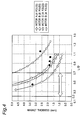
- a relationship between L/D and flux decreasing index is shown in Fig. 5 .
- the magnetic flux quantity derived from the rotor extremely decreases on condition that L/D ⁇ 0.7. That is, on the assumption that L/D ⁇ 0.7, an attempt to shorten the axial length L of the rotor core to shorten the axial length of the motor would cause the magnetic flux leakage from both axial end faces of the rotor to increase, so that the torque of the motor decreases.
- an object of the present invention is to provide a compressor motor, as well as a compressor, which is a small-sized, lightweight and low-priced compressor motor or compressor and in which torque decreases due to large layering-thickness reduction of the rotor is suppressed.
- a compressor motor comprising:
- the compressor motor of this invention given an axial length L of the rotor core, a radial length D of the rotor core and a thickness t of the magnets, it is satisfied that L/D ⁇ 0.7 and that t > (1 ⁇ K ⁇ N)/(L 1.5 ⁇ D ⁇ P). Therefore, even if the axial length of the rotor core is shortened, torque decreases due to magnetic flux leakage from both axial end faces of the rotor can be prevented, so that efficiency decreases can be suppressed.
- a compressor comprising:
- the compressor motor as described above since the compressor motor as described above is included, a small-sized, lightweight, low-priced and high-performance compressor can be achieved.
- the compressor motor of the invention given an axial length L of the rotor core, a radial length D of the rotor core and a thickness t of the magnets, it is satisfied that L/D ⁇ 0.7 and that t > (1 ⁇ K ⁇ N)/(L 1.5 ⁇ D ⁇ P). Therefore, there can be provided a small-sized, lightweight and low-priced motor in which torque decreases due to large reduction in layering thickness of the rotor are suppressed.
- the compressor motor as described above since the compressor motor as described above is included, a small-sized, lightweight, low-priced and high-performance compressor can be achieved.
- Fig. 1 shows a longitudinal sectional view according to an embodiment of the compressor of the invention.
- the compressor includes a closed container 1, a compression element 2 placed within the closed container 1, and a motor 3 placed within the closed container 1 and acting to drive the compression element 2 via a shaft 12.
- This compressor is a so-called vertical high-pressure dome type rotary compressor, in which the compression element 2 is placed below and the motor 3 is placed above within the closed container 1.
- the compression element 2 is driven by a rotor 6 of the motor 3 via the shaft 12.
- the compression element 2 sucks in a refrigerant gas from an accumulator 10 through a suction pipe 11.
- the refrigerant gas can be obtained by controlling unshown condenser, expansion mechanism and evaporator that constitute an air conditioner as an example of a refrigeration system together with the compressor.
- This refrigerant is, for example, carbon dioxide, R410A or R22.
- a compressed high-temperature, high-pressure refrigerant gas is discharged from the compression element 2 to fill the closed container 1 therewith internally, while the refrigerant gas is passed through a gap between a stator 5 and the rotor 6 of the motor 3 to cool the motor 3.
- the refrigerant gas is thereafter discharged outside from a discharge pipe 13 provided on the upper side of the motor 3.
- An oil reservoir 9 in which lubricating oil is accumulated is formed in lower portion of a high-pressure region within the closed container 1.
- This lubricating oil passes from the oil reservoir 9 via an oil passage (not shown) provided in the shaft 12 to move to sliding contact portions such as bearing of the compression element 2 and the motor 3, lubricating the sliding contact portions.
- This lubricating oil is, for example, polyalkylene glycol (polyethylene glycol or polypropylene glycol etc.) oil, ether oil, ester oil, or mineral oil.
- the oil passage is, for example, a spiral groove provided in the outer circumferential surface of the shaft 12 or a hole portion provided inside the shaft 12.
- the compression element 2 includes a cylinder 21 fitted to an inner surface of the closed container 1, and an upper-side end plate member 50 and a lower-side end plate member 60 fitted to upper and lower opening ends of the cylinder 21, respectively.
- a cylinder chamber 22 is defined by the cylinder 21, the upper-side end plate member 50 and the lower-side end plate member 60.
- the upper-side end plate member 50 has a disc-shaped body portion 51, and a boss portion 52 provided upwardly at a center of the body portion 51.
- the shaft 12 is inserted into the body portion 51 and the boss portion 52.
- a delivery valve 31 is mounted on the body portion 51 so as to be positioned on one side of the body portion 51 opposite to the side on which the cylinder 21 is provided.
- This delivery valve 31 is, for example, a reed valve which opens and closes the discharge hole 51a.
- a cup-type muffler cover 40 is mounted on the body portion 51 on its one side opposite to the cylinder 21 so as to cover the delivery valve 31.
- the muffler cover 40 is fixed to the body portion 51 by a fixing member 35 (e.g., bolt).
- the boss portion 52 is inserted into the muffler cover 40.
- the muffler cover 40 and the upper-side end plate member 50 define a muffler chamber 42.
- the muffler chamber 42 and the cylinder chamber 22 are communicated with each other via the discharge hole 51a.
- the muffler cover 40 has a hole portion 43. By the hole portion 43, the muffler chamber 42 and an outer side of the muffler cover 40 are communicated with each other.
- the lower-side end plate member 60 has a disc-shaped body portion 61, and a boss portion 62 provided downwardly at a center of the body portion 61.
- the shaft 12 is inserted into the body portion 61 and the boss portion 62.
- one end portion of the shaft 12 is supported by the upper-side end plate member 50 and the lower-side end plate member 60. That is, the shaft 12 is cantilevered. One end portion (on the support end side) of the shaft 12 intrudes into the cylinder chamber 22.
- an eccentric pin 26 is provided so as to be positioned within the cylinder chamber 22 of the compression element 2.
- the eccentric pin 26 is fitted to a roller 27.
- the roller 27 is placed revolvable in the cylinder chamber 22 so that compression action is exerted by revolving motion of the roller 27.
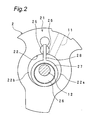
- the cylinder chamber 22 is internally partitioned by a blade 28 integrally provided with the roller 27. That is, in a chamber on the right side of the blade 28, the suction pipe 11 is opened in the inner surface of the cylinder chamber 22 to form a suction chamber (low-pressure chamber) 22a. In a chamber on the left side of the blade 28, the discharge hole 51a (shown in Fig. 1 ) is opened in the inner surface of the cylinder chamber 22 to form a discharge chamber (high-pressure chamber) 22b.
- Semicolumnar-shaped bushes 25, 25 are set in close contact with both surfaces of the blade 28 to provide a seal. Lubrication with the lubricating oil is implemented between the blade 28 and the bushes 25, 25.
- the blade 28 moves back and forth while both side faces of the blade 28 are held by the bushes 25, 25. Then, the low-pressure refrigerant gas is sucked from the suction pipe 11 into the suction chamber 22a and compressed into a high pressure in the discharge chamber 22b, so that a high-pressure refrigerant gas is discharged from the discharge hole 51a (shown in Fig. 1 ).
- the refrigerant gas discharged from the discharge hole 51a is discharged via the muffler chamber 42 outward of the muffler cover 40.
- the motor 3 has the rotor 6, and the stator 5 placed radially outside the rotor 6 with an air gap interposed therebetween.
- the rotor 6 has the rotor core 610, and four magnets 620 embedded in the rotor core 610.
- the rotor core 610 is cylindrical-shaped and formed of, for example, multilayered electromagnetic steel sheets.
- the shaft 12 is mounted at a central hole portion of the rotor core 610.
- the magnets 620 are flat-plate shaped permanent magnets.
- the four magnets 620 are arrayed at center angles of equal intervals in the circumferential direction of the rotor core 610.
- the stator 5 has a stator core 510, and a coil 520 wound around the stator core 510.
- the stator core 510 formed of a plurality of multilayered steel plates, is fitted into the closed container 1 by press fit, shrinkage fit or the like.
- the rotor 6 is rotated together with the shaft 12 by electromagnetic force which is generated in the stator 5 by making a current flow through the coil 520.
- N is a factor responsive to an output of the compressor.
- N is shown in Table 1, Table 2 and Table 3 as an example, and determined by cylinder capacity and refrigerant type.
- the cylinder capacity refers to an effective compression capacity of the compression element 2, i.e., to a capacity of the cylinder chamber 22 corresponding to a maximum-quantity suction of the refrigerant gas into the cylinder chamber 22.
- the relationships that L/D ⁇ 0.7 and that t > (1 ⁇ K ⁇ N)/(L 1.5 ⁇ D ⁇ P) are concurrently satisfied. Therefore, even if the axial length L of the rotor core 610 is shortened, torque decreases due to magnetic flux leakage from both axial end faces of the rotor 6 can be prevented, so that efficiency decreases can be suppressed. That is, the thickness t of the magnets 620 is made larger with shortening axial length L of the rotor core 610. More specifically, as can be seen from the present invention indicated by filled circles in Fig. 5 , under the condition that L/D ⁇ 0.7, flux decreases are prevented and torque decreases due to magnetic flux leakage from the rotor 6 are prevented.
- L/D > 0.2.
- the thickness t of the magnets 620 do not need to be extremely increased, so that efficiency decreases due to magnetic flux leakage from both axial end faces of the rotor 6 can be prevented.
- the magnet thicknesses determined by the calculation and the actual magnet thicknesses are roughly equivalent to each other. Then, the motor 3 of the invention falls within the range of L/D ⁇ 0.7 (preferably, 0.2 ⁇ L/D ⁇ 0.7).
- the compression element 2 may also be a rotary type one in which its roller and blade are provided independent of each other.
- the compression element 2 may further be a scroll type or reciprocating type one other than the rotary type.
- the compression element 2 may yet further be a two-cylinder type one having two cylinder chambers. It is also allowable that the compression element 2 is provided above and the motor 3 is provided below.
- the compressor may also be a so-called low-pressure dome type compressor in which the closed container is filled with a refrigerant that is not yet compressed by the compression element. Further, the number of the magnets 620 may be freely increased or decreased.
Landscapes
- Engineering & Computer Science (AREA)
- Mechanical Engineering (AREA)
- General Engineering & Computer Science (AREA)
- Power Engineering (AREA)
- Applications Or Details Of Rotary Compressors (AREA)
- Compressor (AREA)
- Permanent Field Magnets Of Synchronous Machinery (AREA)
- Permanent Magnet Type Synchronous Machine (AREA)
Applications Claiming Priority (2)
| Application Number | Priority Date | Filing Date | Title |
|---|---|---|---|
| JP2006276080A JP4172514B2 (ja) | 2006-10-10 | 2006-10-10 | 圧縮機 |
| PCT/JP2007/069694 WO2008044684A1 (fr) | 2006-10-10 | 2007-10-09 | Moteur de compresseur et compresseur |
Publications (3)
| Publication Number | Publication Date |
|---|---|
| EP2073350A1 true EP2073350A1 (fr) | 2009-06-24 |
| EP2073350A4 EP2073350A4 (fr) | 2014-01-15 |
| EP2073350B1 EP2073350B1 (fr) | 2017-12-27 |
Family
ID=39282877
Family Applications (1)
| Application Number | Title | Priority Date | Filing Date |
|---|---|---|---|
| EP07829432.9A Active EP2073350B1 (fr) | 2006-10-10 | 2007-10-09 | Moteur de compresseur et compresseur |
Country Status (8)
| Country | Link |
|---|---|
| US (1) | US8004139B2 (fr) |
| EP (1) | EP2073350B1 (fr) |
| JP (1) | JP4172514B2 (fr) |
| KR (1) | KR101001837B1 (fr) |
| CN (1) | CN101517864B (fr) |
| AU (1) | AU2007305528B2 (fr) |
| ES (1) | ES2654914T3 (fr) |
| WO (1) | WO2008044684A1 (fr) |
Cited By (1)
| Publication number | Priority date | Publication date | Assignee | Title |
|---|---|---|---|---|
| EP3309939A4 (fr) * | 2015-06-09 | 2019-01-16 | Mitsubishi Electric Corporation | Moteur électrique de compresseur, compresseur, et dispositif à cycle frigorifique |
Families Citing this family (4)
| Publication number | Priority date | Publication date | Assignee | Title |
|---|---|---|---|---|
| CN103362833B (zh) * | 2012-04-02 | 2016-06-08 | 珠海格力电器股份有限公司 | 直联离心压缩机用悬臂式电机转子及直联式离心压缩机 |
| DE102012213465A1 (de) * | 2012-07-31 | 2014-02-06 | Brose Fahrzeugteile GmbH & Co. Kommanditgesellschaft, Würzburg | Permanentmagnet-Synchronmotor und Servolenkungsanordnung |
| US20160049845A1 (en) * | 2014-08-12 | 2016-02-18 | Zilift Holdings, Limited | Magnetic rotor shaft module and a rotor assembly incorporating the same |
| WO2019123898A1 (fr) * | 2017-12-18 | 2019-06-27 | ダイキン工業株式会社 | Huile pour appareil de réfrigération pour fluide frigorigène ou composition de fluide frigorigène, procédé d'utilisation d'huile pour appareil de réfrigération, et utilisation de l'huile pour appareil de réfrigération |
Family Cites Families (11)
| Publication number | Priority date | Publication date | Assignee | Title |
|---|---|---|---|---|
| US5818139A (en) * | 1994-07-25 | 1998-10-06 | Daikin Industries, Ltd. | Brushless DC motor |
| JP3017085B2 (ja) | 1995-11-02 | 2000-03-06 | 三菱電機株式会社 | 回転電機及びその製造方法 |
| US5811904A (en) * | 1996-03-21 | 1998-09-22 | Hitachi, Ltd. | Permanent magnet dynamo electric machine |
| TW364234B (en) * | 1997-04-14 | 1999-07-11 | Sanyo Electric Co | Rotor for an electric motor |
| JP3301962B2 (ja) * | 1997-04-14 | 2002-07-15 | 三洋電機株式会社 | 電動機の回転子 |
| JP2001342954A (ja) * | 2000-05-31 | 2001-12-14 | Sanyo Electric Co Ltd | 電動圧縮機及びそれを用いた冷却装置 |
| US6987341B2 (en) * | 2002-01-07 | 2006-01-17 | Industrial Technology Research Institute | Motor of rotor with built-in permanent magnet |
| JP2004301038A (ja) * | 2003-03-31 | 2004-10-28 | Fujitsu General Ltd | 密閉型電動圧縮機 |
| US7042127B2 (en) * | 2003-04-02 | 2006-05-09 | Nidec Sankyo Corporation | Permanent magnet embedded motor |
| JP4010319B2 (ja) * | 2005-02-09 | 2007-11-21 | ダイキン工業株式会社 | コア及び回転子並びにモータ及び圧縮機 |
| JP2005229798A (ja) | 2005-02-24 | 2005-08-25 | Sanyo Electric Co Ltd | 冷凍装置 |
-
2006
- 2006-10-10 JP JP2006276080A patent/JP4172514B2/ja active Active
-
2007
- 2007-10-09 ES ES07829432.9T patent/ES2654914T3/es active Active
- 2007-10-09 KR KR1020097007262A patent/KR101001837B1/ko not_active Expired - Fee Related
- 2007-10-09 EP EP07829432.9A patent/EP2073350B1/fr active Active
- 2007-10-09 US US12/444,603 patent/US8004139B2/en not_active Expired - Fee Related
- 2007-10-09 AU AU2007305528A patent/AU2007305528B2/en not_active Ceased
- 2007-10-09 WO PCT/JP2007/069694 patent/WO2008044684A1/fr not_active Ceased
- 2007-10-09 CN CN2007800349608A patent/CN101517864B/zh active Active
Cited By (2)
| Publication number | Priority date | Publication date | Assignee | Title |
|---|---|---|---|---|
| EP3309939A4 (fr) * | 2015-06-09 | 2019-01-16 | Mitsubishi Electric Corporation | Moteur électrique de compresseur, compresseur, et dispositif à cycle frigorifique |
| US10900696B2 (en) | 2015-06-09 | 2021-01-26 | Mitsubishi Electric Corporation | Electric motor for compressor, compressor, and refrigeration cycle device |
Also Published As
| Publication number | Publication date |
|---|---|
| JP4172514B2 (ja) | 2008-10-29 |
| WO2008044684A1 (fr) | 2008-04-17 |
| AU2007305528A1 (en) | 2008-04-17 |
| CN101517864A (zh) | 2009-08-26 |
| ES2654914T3 (es) | 2018-02-15 |
| CN101517864B (zh) | 2011-05-18 |
| KR20090055027A (ko) | 2009-06-01 |
| EP2073350B1 (fr) | 2017-12-27 |
| AU2007305528B2 (en) | 2010-09-30 |
| EP2073350A4 (fr) | 2014-01-15 |
| JP2008099380A (ja) | 2008-04-24 |
| US8004139B2 (en) | 2011-08-23 |
| KR101001837B1 (ko) | 2010-12-15 |
| US20100096940A1 (en) | 2010-04-22 |
Similar Documents
| Publication | Publication Date | Title |
|---|---|---|
| EP2009285B1 (fr) | Compresseur | |
| JP4225353B2 (ja) | ステータ、モータおよび圧縮機 | |
| US10253774B2 (en) | Compressor | |
| EP2090780B1 (fr) | Compresseur | |
| KR20100112486A (ko) | 로터리식 2단 압축기 | |
| EP2073350B1 (fr) | Moteur de compresseur et compresseur | |
| EP1967737A1 (fr) | Compresseur rotatif | |
| KR101380987B1 (ko) | 로터리식 압축기 | |
| JP2009002352A (ja) | 圧縮機 | |
| JP5135779B2 (ja) | 圧縮機 | |
| JP5157148B2 (ja) | 圧縮機 | |
| JP2008141805A (ja) | 圧縮機 | |
| KR20100112488A (ko) | 로터리식 2단 압축기 | |
| JP2025112784A (ja) | 回転圧縮機 | |
| JP2024030863A (ja) | 電動機および圧縮機 | |
| JP4779937B2 (ja) | 圧縮機 | |
| KR20090012860A (ko) | 로터리식 2단 압축기 | |
| JP2021017885A (ja) | スクロール圧縮機 |
Legal Events
| Date | Code | Title | Description |
|---|---|---|---|
| PUAI | Public reference made under article 153(3) epc to a published international application that has entered the european phase |
Free format text: ORIGINAL CODE: 0009012 |
|
| 17P | Request for examination filed |
Effective date: 20090402 |
|
| AK | Designated contracting states |
Kind code of ref document: A1 Designated state(s): AT BE BG CH CY CZ DE DK EE ES FI FR GB GR HU IE IS IT LI LT LU LV MC MT NL PL PT RO SE SI SK TR |
|
| AX | Request for extension of the european patent |
Extension state: AL BA HR MK RS |
|
| DAX | Request for extension of the european patent (deleted) | ||
| A4 | Supplementary search report drawn up and despatched |
Effective date: 20131218 |
|
| RIC1 | Information provided on ipc code assigned before grant |
Ipc: F04B 39/00 20060101ALI20131212BHEP Ipc: H02K 1/27 20060101AFI20131212BHEP Ipc: H02K 21/14 20060101ALI20131212BHEP |
|
| GRAP | Despatch of communication of intention to grant a patent |
Free format text: ORIGINAL CODE: EPIDOSNIGR1 |
|
| STAA | Information on the status of an ep patent application or granted ep patent |
Free format text: STATUS: GRANT OF PATENT IS INTENDED |
|
| INTG | Intention to grant announced |
Effective date: 20170816 |
|
| GRAA | (expected) grant |
Free format text: ORIGINAL CODE: 0009210 |
|
| STAA | Information on the status of an ep patent application or granted ep patent |
Free format text: STATUS: THE PATENT HAS BEEN GRANTED |
|
| GRAS | Grant fee paid |
Free format text: ORIGINAL CODE: EPIDOSNIGR3 |
|
| AK | Designated contracting states |
Kind code of ref document: B1 Designated state(s): AT BE BG CH CY CZ DE DK EE ES FI FR GB GR HU IE IS IT LI LT LU LV MC MT NL PL PT RO SE SI SK TR |
|
| REG | Reference to a national code |
Ref country code: GB Ref legal event code: FG4D |
|
| REG | Reference to a national code |
Ref country code: CH Ref legal event code: EP |
|
| REG | Reference to a national code |
Ref country code: AT Ref legal event code: REF Ref document number: 959085 Country of ref document: AT Kind code of ref document: T Effective date: 20180115 |
|
| REG | Reference to a national code |
Ref country code: IE Ref legal event code: FG4D |
|
| REG | Reference to a national code |
Ref country code: DE Ref legal event code: R096 Ref document number: 602007053567 Country of ref document: DE |
|
| REG | Reference to a national code |
Ref country code: ES Ref legal event code: FG2A Ref document number: 2654914 Country of ref document: ES Kind code of ref document: T3 Effective date: 20180215 |
|
| PG25 | Lapsed in a contracting state [announced via postgrant information from national office to epo] |
Ref country code: FI Free format text: LAPSE BECAUSE OF FAILURE TO SUBMIT A TRANSLATION OF THE DESCRIPTION OR TO PAY THE FEE WITHIN THE PRESCRIBED TIME-LIMIT Effective date: 20171227 Ref country code: LT Free format text: LAPSE BECAUSE OF FAILURE TO SUBMIT A TRANSLATION OF THE DESCRIPTION OR TO PAY THE FEE WITHIN THE PRESCRIBED TIME-LIMIT Effective date: 20171227 |
|
| REG | Reference to a national code |
Ref country code: NL Ref legal event code: MP Effective date: 20171227 |
|
| REG | Reference to a national code |
Ref country code: LT Ref legal event code: MG4D |
|
| REG | Reference to a national code |
Ref country code: AT Ref legal event code: MK05 Ref document number: 959085 Country of ref document: AT Kind code of ref document: T Effective date: 20171227 |
|
| PG25 | Lapsed in a contracting state [announced via postgrant information from national office to epo] |
Ref country code: LV Free format text: LAPSE BECAUSE OF FAILURE TO SUBMIT A TRANSLATION OF THE DESCRIPTION OR TO PAY THE FEE WITHIN THE PRESCRIBED TIME-LIMIT Effective date: 20171227 Ref country code: GR Free format text: LAPSE BECAUSE OF FAILURE TO SUBMIT A TRANSLATION OF THE DESCRIPTION OR TO PAY THE FEE WITHIN THE PRESCRIBED TIME-LIMIT Effective date: 20180328 Ref country code: BG Free format text: LAPSE BECAUSE OF FAILURE TO SUBMIT A TRANSLATION OF THE DESCRIPTION OR TO PAY THE FEE WITHIN THE PRESCRIBED TIME-LIMIT Effective date: 20180327 |
|
| PG25 | Lapsed in a contracting state [announced via postgrant information from national office to epo] |
Ref country code: NL Free format text: LAPSE BECAUSE OF FAILURE TO SUBMIT A TRANSLATION OF THE DESCRIPTION OR TO PAY THE FEE WITHIN THE PRESCRIBED TIME-LIMIT Effective date: 20171227 |
|
| PG25 | Lapsed in a contracting state [announced via postgrant information from national office to epo] |
Ref country code: SK Free format text: LAPSE BECAUSE OF FAILURE TO SUBMIT A TRANSLATION OF THE DESCRIPTION OR TO PAY THE FEE WITHIN THE PRESCRIBED TIME-LIMIT Effective date: 20171227 Ref country code: CZ Free format text: LAPSE BECAUSE OF FAILURE TO SUBMIT A TRANSLATION OF THE DESCRIPTION OR TO PAY THE FEE WITHIN THE PRESCRIBED TIME-LIMIT Effective date: 20171227 Ref country code: CY Free format text: LAPSE BECAUSE OF FAILURE TO SUBMIT A TRANSLATION OF THE DESCRIPTION OR TO PAY THE FEE WITHIN THE PRESCRIBED TIME-LIMIT Effective date: 20171227 Ref country code: EE Free format text: LAPSE BECAUSE OF FAILURE TO SUBMIT A TRANSLATION OF THE DESCRIPTION OR TO PAY THE FEE WITHIN THE PRESCRIBED TIME-LIMIT Effective date: 20171227 |
|
| PG25 | Lapsed in a contracting state [announced via postgrant information from national office to epo] |
Ref country code: RO Free format text: LAPSE BECAUSE OF FAILURE TO SUBMIT A TRANSLATION OF THE DESCRIPTION OR TO PAY THE FEE WITHIN THE PRESCRIBED TIME-LIMIT Effective date: 20171227 Ref country code: IS Free format text: LAPSE BECAUSE OF FAILURE TO SUBMIT A TRANSLATION OF THE DESCRIPTION OR TO PAY THE FEE WITHIN THE PRESCRIBED TIME-LIMIT Effective date: 20180427 Ref country code: AT Free format text: LAPSE BECAUSE OF FAILURE TO SUBMIT A TRANSLATION OF THE DESCRIPTION OR TO PAY THE FEE WITHIN THE PRESCRIBED TIME-LIMIT Effective date: 20171227 Ref country code: PL Free format text: LAPSE BECAUSE OF FAILURE TO SUBMIT A TRANSLATION OF THE DESCRIPTION OR TO PAY THE FEE WITHIN THE PRESCRIBED TIME-LIMIT Effective date: 20171227 |
|
| REG | Reference to a national code |
Ref country code: FR Ref legal event code: PLFP Year of fee payment: 12 |
|
| REG | Reference to a national code |
Ref country code: DE Ref legal event code: R097 Ref document number: 602007053567 Country of ref document: DE |
|
| PLBE | No opposition filed within time limit |
Free format text: ORIGINAL CODE: 0009261 |
|
| STAA | Information on the status of an ep patent application or granted ep patent |
Free format text: STATUS: NO OPPOSITION FILED WITHIN TIME LIMIT |
|
| PG25 | Lapsed in a contracting state [announced via postgrant information from national office to epo] |
Ref country code: DK Free format text: LAPSE BECAUSE OF FAILURE TO SUBMIT A TRANSLATION OF THE DESCRIPTION OR TO PAY THE FEE WITHIN THE PRESCRIBED TIME-LIMIT Effective date: 20171227 |
|
| 26N | No opposition filed |
Effective date: 20180928 |
|
| PG25 | Lapsed in a contracting state [announced via postgrant information from national office to epo] |
Ref country code: SI Free format text: LAPSE BECAUSE OF FAILURE TO SUBMIT A TRANSLATION OF THE DESCRIPTION OR TO PAY THE FEE WITHIN THE PRESCRIBED TIME-LIMIT Effective date: 20171227 |
|
| REG | Reference to a national code |
Ref country code: CH Ref legal event code: PL |
|
| REG | Reference to a national code |
Ref country code: BE Ref legal event code: MM Effective date: 20181031 |
|
| PG25 | Lapsed in a contracting state [announced via postgrant information from national office to epo] |
Ref country code: LU Free format text: LAPSE BECAUSE OF NON-PAYMENT OF DUE FEES Effective date: 20181009 Ref country code: MC Free format text: LAPSE BECAUSE OF FAILURE TO SUBMIT A TRANSLATION OF THE DESCRIPTION OR TO PAY THE FEE WITHIN THE PRESCRIBED TIME-LIMIT Effective date: 20171227 |
|
| REG | Reference to a national code |
Ref country code: IE Ref legal event code: MM4A |
|
| PG25 | Lapsed in a contracting state [announced via postgrant information from national office to epo] |
Ref country code: LI Free format text: LAPSE BECAUSE OF NON-PAYMENT OF DUE FEES Effective date: 20181031 Ref country code: CH Free format text: LAPSE BECAUSE OF NON-PAYMENT OF DUE FEES Effective date: 20181031 Ref country code: BE Free format text: LAPSE BECAUSE OF NON-PAYMENT OF DUE FEES Effective date: 20181031 |
|
| PG25 | Lapsed in a contracting state [announced via postgrant information from national office to epo] |
Ref country code: IE Free format text: LAPSE BECAUSE OF NON-PAYMENT OF DUE FEES Effective date: 20181009 |
|
| PG25 | Lapsed in a contracting state [announced via postgrant information from national office to epo] |
Ref country code: MT Free format text: LAPSE BECAUSE OF NON-PAYMENT OF DUE FEES Effective date: 20181009 |
|
| PG25 | Lapsed in a contracting state [announced via postgrant information from national office to epo] |
Ref country code: TR Free format text: LAPSE BECAUSE OF FAILURE TO SUBMIT A TRANSLATION OF THE DESCRIPTION OR TO PAY THE FEE WITHIN THE PRESCRIBED TIME-LIMIT Effective date: 20171227 |
|
| PG25 | Lapsed in a contracting state [announced via postgrant information from national office to epo] |
Ref country code: PT Free format text: LAPSE BECAUSE OF FAILURE TO SUBMIT A TRANSLATION OF THE DESCRIPTION OR TO PAY THE FEE WITHIN THE PRESCRIBED TIME-LIMIT Effective date: 20171227 |
|
| PG25 | Lapsed in a contracting state [announced via postgrant information from national office to epo] |
Ref country code: HU Free format text: LAPSE BECAUSE OF FAILURE TO SUBMIT A TRANSLATION OF THE DESCRIPTION OR TO PAY THE FEE WITHIN THE PRESCRIBED TIME-LIMIT; INVALID AB INITIO Effective date: 20071009 Ref country code: SE Free format text: LAPSE BECAUSE OF FAILURE TO SUBMIT A TRANSLATION OF THE DESCRIPTION OR TO PAY THE FEE WITHIN THE PRESCRIBED TIME-LIMIT Effective date: 20171227 |
|
| P01 | Opt-out of the competence of the unified patent court (upc) registered |
Effective date: 20230525 |
|
| PGFP | Annual fee paid to national office [announced via postgrant information from national office to epo] |
Ref country code: GB Payment date: 20240829 Year of fee payment: 18 |
|
| PGFP | Annual fee paid to national office [announced via postgrant information from national office to epo] |
Ref country code: FR Payment date: 20240909 Year of fee payment: 18 |
|
| PGFP | Annual fee paid to national office [announced via postgrant information from national office to epo] |
Ref country code: IT Payment date: 20240910 Year of fee payment: 18 |
|
| PGFP | Annual fee paid to national office [announced via postgrant information from national office to epo] |
Ref country code: DE Payment date: 20240828 Year of fee payment: 18 |
|
| PGFP | Annual fee paid to national office [announced via postgrant information from national office to epo] |
Ref country code: ES Payment date: 20241101 Year of fee payment: 18 |