EP2073373A2 - Procédé pour contrôler le moteur d'un climatiseur - Google Patents
Procédé pour contrôler le moteur d'un climatiseur Download PDFInfo
- Publication number
- EP2073373A2 EP2073373A2 EP08254004A EP08254004A EP2073373A2 EP 2073373 A2 EP2073373 A2 EP 2073373A2 EP 08254004 A EP08254004 A EP 08254004A EP 08254004 A EP08254004 A EP 08254004A EP 2073373 A2 EP2073373 A2 EP 2073373A2
- Authority
- EP
- European Patent Office
- Prior art keywords
- motor
- switching elements
- arm switching
- lower arm
- air conditioner
- Prior art date
- Legal status (The legal status is an assumption and is not a legal conclusion. Google has not performed a legal analysis and makes no representation as to the accuracy of the status listed.)
- Withdrawn
Links
- 238000000034 method Methods 0.000 title claims abstract description 25
- 230000003313 weakening effect Effects 0.000 claims abstract description 19
- 230000004907 flux Effects 0.000 claims abstract description 6
- 230000003247 decreasing effect Effects 0.000 claims 1
- 238000001514 detection method Methods 0.000 description 10
- 239000003507 refrigerant Substances 0.000 description 10
- 238000010586 diagram Methods 0.000 description 8
- 238000001816 cooling Methods 0.000 description 7
- 230000017525 heat dissipation Effects 0.000 description 4
- 238000010438 heat treatment Methods 0.000 description 4
- 239000003990 capacitor Substances 0.000 description 3
- 238000009499 grossing Methods 0.000 description 3
- 238000009423 ventilation Methods 0.000 description 2
- 238000006243 chemical reaction Methods 0.000 description 1
- 238000004140 cleaning Methods 0.000 description 1
- 230000006835 compression Effects 0.000 description 1
- 238000007906 compression Methods 0.000 description 1
- 230000007246 mechanism Effects 0.000 description 1
- 238000012986 modification Methods 0.000 description 1
- 230000004048 modification Effects 0.000 description 1
- 239000000126 substance Substances 0.000 description 1
Images



Classifications
-
- H—ELECTRICITY
- H02—GENERATION; CONVERSION OR DISTRIBUTION OF ELECTRIC POWER
- H02P—CONTROL OR REGULATION OF ELECTRIC MOTORS, ELECTRIC GENERATORS OR DYNAMO-ELECTRIC CONVERTERS; CONTROLLING TRANSFORMERS, REACTORS OR CHOKE COILS
- H02P23/00—Arrangements or methods for the control of AC motors characterised by a control method other than vector control
- H02P23/0004—Control strategies in general, e.g. linear type, e.g. P, PI, PID, using robust control
-
- F—MECHANICAL ENGINEERING; LIGHTING; HEATING; WEAPONS; BLASTING
- F25—REFRIGERATION OR COOLING; COMBINED HEATING AND REFRIGERATION SYSTEMS; HEAT PUMP SYSTEMS; MANUFACTURE OR STORAGE OF ICE; LIQUEFACTION SOLIDIFICATION OF GASES
- F25B—REFRIGERATION MACHINES, PLANTS OR SYSTEMS; COMBINED HEATING AND REFRIGERATION SYSTEMS; HEAT PUMP SYSTEMS
- F25B13/00—Compression machines, plants or systems, with reversible cycle
-
- H—ELECTRICITY
- H02—GENERATION; CONVERSION OR DISTRIBUTION OF ELECTRIC POWER
- H02P—CONTROL OR REGULATION OF ELECTRIC MOTORS, ELECTRIC GENERATORS OR DYNAMO-ELECTRIC CONVERTERS; CONTROLLING TRANSFORMERS, REACTORS OR CHOKE COILS
- H02P21/00—Arrangements or methods for the control of electric machines by vector control, e.g. by control of field orientation
- H02P21/0085—Arrangements or methods for the control of electric machines by vector control, e.g. by control of field orientation specially adapted for high speeds, e.g. above nominal speed
- H02P21/0089—Arrangements or methods for the control of electric machines by vector control, e.g. by control of field orientation specially adapted for high speeds, e.g. above nominal speed using field weakening
-
- H—ELECTRICITY
- H02—GENERATION; CONVERSION OR DISTRIBUTION OF ELECTRIC POWER
- H02P—CONTROL OR REGULATION OF ELECTRIC MOTORS, ELECTRIC GENERATORS OR DYNAMO-ELECTRIC CONVERTERS; CONTROLLING TRANSFORMERS, REACTORS OR CHOKE COILS
- H02P25/00—Arrangements or methods for the control of AC motors characterised by the kind of AC motor or by structural details
- H02P25/02—Arrangements or methods for the control of AC motors characterised by the kind of AC motor or by structural details characterised by the kind of motor
- H02P25/022—Synchronous motors
- H02P25/03—Synchronous motors with brushless excitation
-
- H—ELECTRICITY
- H02—GENERATION; CONVERSION OR DISTRIBUTION OF ELECTRIC POWER
- H02P—CONTROL OR REGULATION OF ELECTRIC MOTORS, ELECTRIC GENERATORS OR DYNAMO-ELECTRIC CONVERTERS; CONTROLLING TRANSFORMERS, REACTORS OR CHOKE COILS
- H02P27/00—Arrangements or methods for the control of AC motors characterised by the kind of supply voltage
- H02P27/04—Arrangements or methods for the control of AC motors characterised by the kind of supply voltage using variable-frequency supply voltage, e.g. inverter or converter supply voltage
- H02P27/06—Arrangements or methods for the control of AC motors characterised by the kind of supply voltage using variable-frequency supply voltage, e.g. inverter or converter supply voltage using DC to AC converters or inverters
-
- F—MECHANICAL ENGINEERING; LIGHTING; HEATING; WEAPONS; BLASTING
- F24—HEATING; RANGES; VENTILATING
- F24F—AIR-CONDITIONING; AIR-HUMIDIFICATION; VENTILATION; USE OF AIR CURRENTS FOR SCREENING
- F24F11/00—Control or safety arrangements
- F24F11/70—Control systems characterised by their outputs; Constructional details thereof
- F24F11/72—Control systems characterised by their outputs; Constructional details thereof for controlling the supply of treated air, e.g. its pressure
- F24F11/74—Control systems characterised by their outputs; Constructional details thereof for controlling the supply of treated air, e.g. its pressure for controlling air flow rate or air velocity
- F24F11/77—Control systems characterised by their outputs; Constructional details thereof for controlling the supply of treated air, e.g. its pressure for controlling air flow rate or air velocity by controlling the speed of ventilators
-
- F—MECHANICAL ENGINEERING; LIGHTING; HEATING; WEAPONS; BLASTING
- F25—REFRIGERATION OR COOLING; COMBINED HEATING AND REFRIGERATION SYSTEMS; HEAT PUMP SYSTEMS; MANUFACTURE OR STORAGE OF ICE; LIQUEFACTION SOLIDIFICATION OF GASES
- F25B—REFRIGERATION MACHINES, PLANTS OR SYSTEMS; COMBINED HEATING AND REFRIGERATION SYSTEMS; HEAT PUMP SYSTEMS
- F25B2600/00—Control issues
- F25B2600/02—Compressor control
- F25B2600/021—Inverters therefor
-
- F—MECHANICAL ENGINEERING; LIGHTING; HEATING; WEAPONS; BLASTING
- F25—REFRIGERATION OR COOLING; COMBINED HEATING AND REFRIGERATION SYSTEMS; HEAT PUMP SYSTEMS; MANUFACTURE OR STORAGE OF ICE; LIQUEFACTION SOLIDIFICATION OF GASES
- F25B—REFRIGERATION MACHINES, PLANTS OR SYSTEMS; COMBINED HEATING AND REFRIGERATION SYSTEMS; HEAT PUMP SYSTEMS
- F25B2700/00—Sensing or detecting of parameters; Sensors therefor
- F25B2700/15—Power, e.g. by voltage or current
-
- Y—GENERAL TAGGING OF NEW TECHNOLOGICAL DEVELOPMENTS; GENERAL TAGGING OF CROSS-SECTIONAL TECHNOLOGIES SPANNING OVER SEVERAL SECTIONS OF THE IPC; TECHNICAL SUBJECTS COVERED BY FORMER USPC CROSS-REFERENCE ART COLLECTIONS [XRACs] AND DIGESTS
- Y02—TECHNOLOGIES OR APPLICATIONS FOR MITIGATION OR ADAPTATION AGAINST CLIMATE CHANGE
- Y02B—CLIMATE CHANGE MITIGATION TECHNOLOGIES RELATED TO BUILDINGS, e.g. HOUSING, HOUSE APPLIANCES OR RELATED END-USER APPLICATIONS
- Y02B30/00—Energy efficient heating, ventilation or air conditioning [HVAC]
- Y02B30/70—Efficient control or regulation technologies, e.g. for control of refrigerant flow, motor or heating
Definitions
- the present invention relates to a method of controlling a motor of an air conditioner, and more specifically to a method of controlling a motor of an air conditioner, which can ensure a minimum zero vector application time.
- An air conditioner is an apparatus disposed in space, such as rooms, dining rooms, office rooms, and shops, and adapted to control temperature, moisture, cleaning and air stream of the air in order to maintain pleasant indoor environments.
- An air conditioner is generally divided into a unit type and a separate type.
- the unit type and the separate type are identical in terms of their functions.
- the unit type includes an integrated cooling and heat-dissipation function and is installed in a wall of a house or hung on a wall.
- an indoor unit having the cooling/heating functions is installed indoors and an outdoor unit having the heat-dissipation and compression functions is installed outdoors and thereafter both the units are connected by refrigerant ducts.
- the air conditioner uses motors for compressors, fans, and so on and also employs a method of controlling the motors for driving them. That is, a motor control method of converting commercial AC power into DC power and converting the DC power into AC power of a specific frequency again is used.
- An object of the present invention is to provide a method of controlling a motor of an air conditioner, which can ensure a minimum zero vector application time.
- a method of controlling a motor of an air conditioner in accordance with an embodiment of the present invention can ensure an application time of a minimum zero vector.
- an output current can be detected stably. Consequently, at the time of control, accurate control is made possible.
- FIG. 1 is a schematic view of an air conditioner pertinent the present invention.
- an air conditioner 50 is largely divided into an indoor unit I and an outdoor unit O.
- the outdoor unit O includes a compressor 2 functioning to compress refrigerant, a motor 2b for the compressor for driving the compressor, an outdoor-side heat exchanger 4 functioning to dissipate heat of compressed refrigerant, an outdoor ventilation fan 5, including an outdoor fan 5a disposed on one side of the outdoor heat exchanger 5 and configured to accelerate heat dissipation of refrigerant and a motor 5b for rotating the outdoor fan 5a, an expansion mechanism 6 for expanding condensed refrigerant, a cooling/heating switching valve 10 for switching the flow passage of compressed refrigerant, an accumulator 3 for temporarily storing vaporized refrigerant, removing moisture and alien substance from the refrigerant and supplying refrigerant of a specific pressure to the compressor, and so on.
- the indoor unit I includes an indoor-side heat exchanger 8 disposed indoor and performing a cooling/heating function, an indoor ventilation fan 9 disposed on one side of the indoor-side heat exchanger 8 and including an indoor fan 9a for accelerating heat dissipation of refrigerant and a motor 9b for rotating the indoor fan 9a, and so on.
- At least one indoor-side heat exchanger 8 can be installed.
- the compressor 2 can employ at least one of an inverter compressor and a constant speed compressor.
- the air conditioner 50 can be constructed as a cooling device for cooling the indoor or a heat pump for cooling or heating the indoor.
- the motor in the motor controller of the air conditioner in accordance with an embodiment of the present invention can be each of motor 2b, 5b,and 9b for operating the compressor, the outdoor fan, and the indoor fan.
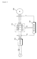
- FIG. 2 is a block diagram showing a motor controller of an air conditioner, which is related to a method of controlling a motor of the air conditioner in accordance with the present invention.
- FIG. 3 is a diagram showing field weakening control.
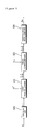
- FIG. 4 is a timing diagram showing SVPWM waveforms.
- FIG. 5 is an internal block diagram of the microcomputer of FIG. 2 .
- the motor controller 200 of the air conditioner in accordance with the present invention includes a converter 210, an inverter 220, and a microcomputer 230.
- the motor controller 200 of the air conditioner of FIG. 2 may further include a reactor L, a smoothing capacitor C, dc terminal voltage detection means, output current detection means E, and so on.
- the reactor L is disposed between commercial AC power and the converter 210 and performs power factor correction or a boosting operation.
- the reactor L can also function to limit the harmonic current through high-speed switching of the converter.
- the converter 210 converts the commercial AC power, passing through the reactor L, into DC power and outputs converted DC power.
- the commercial AC power has been illustrated as single-phase AC power, it may be three-phase AC power.
- An internal configuration of the converter 210 may vary depending on the type of commercial AC power. For example, in the case of single-phase AC power, a half-bridge type converter having two switching elements and four diodes connected may be used. In the case of three-phase AC power, six switching elements and six diodes may be used.
- the converter 210 includes a plurality of switching elements and performs a boosting operation, power factor improvements and DC power conversion through the switching operation.
- the smoothing capacitor C is connected to the output terminal of the converter 210 and functions to smooth converted DC power output from the converter 210.
- the output terminal of the converter 210 is hereinafter referred to as a 'dc terminal' or a 'dc link terminal'.
- the DC voltage smoothed at the dc terminal is applied to the inverter 220.
- the dc terminal voltage detection means D detects a dc terminal voltage Vdc across the smoothing capacitor C. To this end, the dc terminal voltage detection means D includes a resistor element, etc. The detected dc terminal voltage Vdc is input to the microcomputer 230 for purposes of generating a converter switching control signal Scc or field weakening control. Contents regarding field weakening control will be described later on with reference to FIG. 3 .
- the inverter 220 includes a plurality of inverter switching elements.
- the inverter 220 converts smoothed DC power into three-phase AC power of a specific frequency through the on/off operations of the switching elements and outputs the converted AC power. More specifically, an upper arm switching element and a lower arm switching element, which are connected in series, form one pair. A total of three pairs of the upper and lower arm switching elements Sa&Sa', Sb&Sb', and Sc&Sc' are connected in parallel.
- the three-phase AC power output from the inverter 220 is applied to respective phases u, v, and w of a three-phase motor 250.
- the three-phase motor 250 is equipped with a stator and a rotor. Each phase AC power having a specific frequency is applied to the stator coil of each phase, so that the rotor is rotated.
- Types of the three-phase motor 250 can be a BLDC motor.
- the output current detection means E detects an output current at the output terminal of the inverter 220, which flows through the motor 250.
- the output current detection means E may be located between the inverter 220 and the motor 250 and may employ a current sensor, a current transformer (CT), a shunt resistor or the like for current detection.
- CT current transformer
- the output current detection means E may be a shunt resistor having one terminal connected to the three lower arm switching elements of the inverter 220.
- a detected output current i o is input to the microcomputer 230, and an inverter switching control signal Sic is generated based on the detected output current i o .
- the microcomputer 230 controls the inverter 220. To this end, the microcomputer 230 outputs the inverter switching control signal Sic, that is, a PWM signal to the inverter 220 and therefore controls the on/off operations of the switching elements within the inverter 220.
- Sic the inverter switching control signal
- the microcomputer 230 includes an estimation unit 505, a current command generator 510, a voltage command generator 520, and a switching control signal output unit 530.
- the estimation unit 505 estimates the position and velocity v of the rotor of the motor based on the output current i o detected by the output current detection means E.
- the current command generator 510 generates d,q-axis current command values i * d , i * q based on the estimated velocity v and a velocity command value v * through a PI controller, etc.
- the voltage command generator 520 generates d,q-axis voltage command values v * d , v * q based on the d,q-axis current command values i * d , i * q and a detected output current i o through a PI controller, etc.
- the switching control signal output unit 530 outputs the switching control signal Sic, that is, a PWM signal based on the d,q-axis voltage command values v * d , v * q in order to drive the inverter switching elements.
- the output current i o input to the voltage command generator 520 can be a value that is transformed in the d,q axes.
- the microcomputer 230 performs field weakening control in order to drive the motor to a maximum velocity. If a permanent magnet of the motor 250 is rotated, counter electromotive force is generated. The amount of counter electromotive force increases as the velocity of the motor 250 increases. Thus, the velocity of the motor 250 is limited according to a limit value of DC power (dc terminal power).
- field weakening control for controlling the velocity of the motor by generating current, which offsets the amount of magnetic flux generated in the permanent magnet, is performed.
- an abscissa axis is a d-axis current i d of the rotating reference frames and a vertical axis is a q-axis current iq.
- a curve L denotes a current limit curve from the d-axis current i d and the q-axis current iq.
- a curve M denotes a voltage limit curve according to the limit value of the dc terminal voltage Vdc.
- a curve N denotes an optimal current command curve decided according to the velocity command value v * in the current command generator (510 of FIG. 5 ).
- a period (1) of FIG. 3 shows that the current command values i * d , i * q are decided according to the optimal current command curve N in such a way as to track the velocity command value v * as the velocity command value v * increases.
- the current command values i * d , i * q are decided according to the period (1) and the voltage limit curve M is reached, the current command values of the motor do no longer track the optimal current command curve N. That is, it becomes a state where a maximum value of the dc terminal voltage Vdc is used, so that the velocity of the motor 250 is no longer increased.
- the microcomputer 230 performs field weakening control for controlling the velocity of the motor by generating current, which offsets the amount of magnetic flux generated in the permanent magnet. That is, the d-axis current command value i * d is further lowered below the optimal current command curve N and the q-axis current command value i * q is increased that much. In other words, the microcomputer 230 tracks a period (2) in order to decide the current command values i * d , i * q according to the voltage limit curve M.
- the microcomputer 230 controls a first zero vector application time (T o1 /2), applied to the upper arm switching elements Sa, Sb, and Sc within the inverter, or a second zero vector application time (T o2 /2), applied to the lower arm switching elements Sa', Sb', and Sc' within the inverter, to become a specific value or more.
- the specific value can be decided based on the output current i o flowing through the motor 250. That is, the specific value is decided according to a minimum value of the output current i o at the time of field weakening control.
- the specific value is set based on a minimum duty ratio applied to the motor 250.
- the minimum duty ratio is 10%, a corresponding time can become the specific value.
- This minimum duty ratio can be a value set to detect the output current i o .
- the full duty of the inverter switching control signal Sic can be set to 90%. This value can be set to detect the output current i o .
- the first zero vector application time (T o1 /2) applied to the upper arm switching elements Sa, Sb, and Sc or the second zero vector application time (T o2 /2) applied to the lower arm switching elements Sa', Sb', and Sc' is preferably set to be a specific time or more in which the output current detection means E can detect the output current i o .
- the switching control signal can be generated based on the output current i o by detecting the output current i o . That is, stable and accurate control is made possible.
- FIG. 4 shows on/off timings of the respective switching elements Sa, Sb, and Sc.
- Ts denotes a unit switching control time.
- the method of controlling a motor of an air conditioner in accordance with the present invention can be employed to ensure a minimum zero vector application time so that an output current can be detected stably when detecting the output current.
Landscapes
- Engineering & Computer Science (AREA)
- Power Engineering (AREA)
- Physics & Mathematics (AREA)
- Mechanical Engineering (AREA)
- Thermal Sciences (AREA)
- General Engineering & Computer Science (AREA)
- Control Of Motors That Do Not Use Commutators (AREA)
- Control Of Ac Motors In General (AREA)
Applications Claiming Priority (1)
| Application Number | Priority Date | Filing Date | Title |
|---|---|---|---|
| KR1020070135490A KR101561922B1 (ko) | 2007-12-21 | 2007-12-21 | 공기조화기의 전동기 제어방법 |
Publications (2)
| Publication Number | Publication Date |
|---|---|
| EP2073373A2 true EP2073373A2 (fr) | 2009-06-24 |
| EP2073373A3 EP2073373A3 (fr) | 2016-12-28 |
Family
ID=40351818
Family Applications (1)
| Application Number | Title | Priority Date | Filing Date |
|---|---|---|---|
| EP08254004.8A Withdrawn EP2073373A3 (fr) | 2007-12-21 | 2008-12-15 | Procédé pour contrôler le moteur d'un climatiseur |
Country Status (4)
| Country | Link |
|---|---|
| US (1) | US20090164047A1 (fr) |
| EP (1) | EP2073373A3 (fr) |
| KR (1) | KR101561922B1 (fr) |
| WO (1) | WO2009082068A2 (fr) |
Cited By (1)
| Publication number | Priority date | Publication date | Assignee | Title |
|---|---|---|---|---|
| CN114738977A (zh) * | 2022-03-30 | 2022-07-12 | 北京小米移动软件有限公司 | 空调弱磁角度控制方法、装置及存储介质 |
Families Citing this family (7)
| Publication number | Priority date | Publication date | Assignee | Title |
|---|---|---|---|---|
| KR101691809B1 (ko) * | 2009-08-04 | 2017-01-09 | 엘지전자 주식회사 | 분산전원을 이용한 전동기 구동장치 및 분산전원 시스템 |
| CN102116516A (zh) * | 2010-12-21 | 2011-07-06 | 芜湖安得物流股份有限公司 | 物流仓库空调节电装置 |
| WO2012098875A1 (fr) * | 2011-01-18 | 2012-07-26 | ダイキン工業株式会社 | Appareil de conversion d'électricité |
| WO2012107987A1 (fr) * | 2011-02-07 | 2012-08-16 | 三菱電機株式会社 | Dispositif de pompe à chaleur, système de pompe à chaleur, et procédé de commande pour convertisseur triphasé |
| KR101698775B1 (ko) * | 2015-08-11 | 2017-01-23 | 엘지전자 주식회사 | 홈 어플라이언스 |
| US10581274B2 (en) | 2015-06-03 | 2020-03-03 | Lg Electronics Inc. | Home appliance |
| KR101663520B1 (ko) * | 2015-08-11 | 2016-10-07 | 엘지전자 주식회사 | 모터 구동장치 및 이를 구비하는 홈 어플라이언스 |
Citations (2)
| Publication number | Priority date | Publication date | Assignee | Title |
|---|---|---|---|---|
| US5729102A (en) * | 1995-06-30 | 1998-03-17 | Matsushita Electric Industrial Co., Ltd. | Brushless motor |
| WO2005074115A1 (fr) * | 2004-01-30 | 2005-08-11 | Matsushita Electric Industrial Co., Ltd. | Methode de controle sans capteur de position du moteur synchrone a aimant permanent avec shunt du module onduleur |
Family Cites Families (18)
| Publication number | Priority date | Publication date | Assignee | Title |
|---|---|---|---|---|
| JPH0755080B2 (ja) * | 1989-09-29 | 1995-06-07 | 譲 常広 | インバータの制御装置 |
| JP3371314B2 (ja) * | 1995-03-24 | 2003-01-27 | セイコーエプソン株式会社 | Dcブラシレスモータおよび制御装置 |
| JP4051833B2 (ja) | 1999-09-06 | 2008-02-27 | 株式会社明電舎 | 永久磁石式同期電動機のベクトル制御装置 |
| JP3454212B2 (ja) * | 1999-12-02 | 2003-10-06 | 株式会社日立製作所 | モータ制御装置 |
| JP3566163B2 (ja) * | 2000-01-07 | 2004-09-15 | 株式会社東芝 | モータ制御装置 |
| US6316904B1 (en) * | 2000-06-27 | 2001-11-13 | Ford Global Technologies, Inc. | Speed and rotor time constant estimation for torque control of an induction motor |
| JP3879414B2 (ja) * | 2001-02-28 | 2007-02-14 | 株式会社日立製作所 | 空気調和機 |
| EP1378990B1 (fr) * | 2001-03-02 | 2007-12-12 | Matsushita Electric Industrial Co., Ltd. | Contrôleur pour un moteur électrique |
| KR100451233B1 (ko) * | 2002-03-16 | 2004-10-02 | 엘지전자 주식회사 | 왕복동식 압축기의 운전제어방법 |
| JP3971979B2 (ja) * | 2002-09-13 | 2007-09-05 | 日立アプライアンス株式会社 | 空気調和装置 |
| US6876169B2 (en) * | 2003-01-14 | 2005-04-05 | Delphi Technologies, Inc. | Method and controller for field weakening operation of AC machines |
| KR100702913B1 (ko) * | 2003-03-17 | 2007-04-03 | 마쯔시다덴기산교 가부시키가이샤 | 브러시리스 dc 모터의 구동 방법 및 그 장치 |
| KR100645808B1 (ko) * | 2004-12-08 | 2006-11-23 | 엘지전자 주식회사 | 모터 제어방법 |
| US7141949B2 (en) * | 2005-03-07 | 2006-11-28 | Fisher & Paykel Appliances Limited | Low noise back EMF sensing brushless DC motor |
| US7652441B2 (en) * | 2005-07-01 | 2010-01-26 | International Rectifier Corporation | Method and system for starting a sensorless motor |
| JP4674516B2 (ja) * | 2005-09-27 | 2011-04-20 | 株式会社デンソー | 同期モータの磁極位置推定方法 |
| JP4895703B2 (ja) * | 2006-06-28 | 2012-03-14 | 三洋電機株式会社 | モータ制御装置 |
| US8138697B2 (en) * | 2007-04-27 | 2012-03-20 | International Rectifier Corporation | Sensorless speed detection during zero vector |
-
2007
- 2007-12-21 KR KR1020070135490A patent/KR101561922B1/ko not_active Expired - Fee Related
-
2008
- 2008-04-30 WO PCT/KR2008/002447 patent/WO2009082068A2/fr not_active Ceased
- 2008-12-15 EP EP08254004.8A patent/EP2073373A3/fr not_active Withdrawn
- 2008-12-19 US US12/318,058 patent/US20090164047A1/en not_active Abandoned
Patent Citations (2)
| Publication number | Priority date | Publication date | Assignee | Title |
|---|---|---|---|---|
| US5729102A (en) * | 1995-06-30 | 1998-03-17 | Matsushita Electric Industrial Co., Ltd. | Brushless motor |
| WO2005074115A1 (fr) * | 2004-01-30 | 2005-08-11 | Matsushita Electric Industrial Co., Ltd. | Methode de controle sans capteur de position du moteur synchrone a aimant permanent avec shunt du module onduleur |
Cited By (2)
| Publication number | Priority date | Publication date | Assignee | Title |
|---|---|---|---|---|
| CN114738977A (zh) * | 2022-03-30 | 2022-07-12 | 北京小米移动软件有限公司 | 空调弱磁角度控制方法、装置及存储介质 |
| CN114738977B (zh) * | 2022-03-30 | 2024-04-09 | 北京小米移动软件有限公司 | 空调弱磁角度控制方法、装置及存储介质 |
Also Published As
| Publication number | Publication date |
|---|---|
| KR20090067732A (ko) | 2009-06-25 |
| EP2073373A3 (fr) | 2016-12-28 |
| KR101561922B1 (ko) | 2015-10-20 |
| WO2009082068A3 (fr) | 2012-09-07 |
| WO2009082068A2 (fr) | 2009-07-02 |
| US20090164047A1 (en) | 2009-06-25 |
Similar Documents
| Publication | Publication Date | Title |
|---|---|---|
| US8120299B2 (en) | Motor controller of air conditioner | |
| EP2073373A2 (fr) | Procédé pour contrôler le moteur d'un climatiseur | |
| KR101461559B1 (ko) | 공기조화기의 전동기 제어장치 | |
| WO2005067131A1 (fr) | Procede d'entrainement et dispositif d'entrainement d'un moteur a courant continu sans balai | |
| JP4744505B2 (ja) | モータ駆動制御装置、モータ駆動制御方法及び座標変換方法、並びに換気扇、液体用ポンプ、送風機、冷媒圧縮機、空気調和機及び冷蔵庫 | |
| KR20190051331A (ko) | 전력변환장치 및 이를 구비하는 공기조화기 | |
| WO2009064050A2 (fr) | Commande moteur d'un climatiseur | |
| KR101054439B1 (ko) | 공기조화기의 전동기 구동장치 | |
| KR20210108251A (ko) | 모터 구동 장치 및 이를 구비하는 공기조화기 | |
| KR101591326B1 (ko) | 공기조화기의 전동기 구동장치 | |
| KR101054438B1 (ko) | 공기조화기의 전동기 구동장치 | |
| KR102010388B1 (ko) | 모터 구동장치 및 이를 구비하는 공기조화기 | |
| KR102010387B1 (ko) | 전력변환장치 및 이를 구비하는 공기조화기 | |
| KR20090081914A (ko) | 공기조화기의 전동기 제어장치 | |
| KR20090049849A (ko) | 공기조화기의 전동기 제어장치 | |
| KR20090042519A (ko) | 전동기 판별 방법 및 그 판별 장치 | |
| KR100925276B1 (ko) | 전동기 제어 장치 및 그 제어 방법 | |
| KR20200013501A (ko) | 모터 구동장치 및 이를 구비하는 공기조화기 | |
| KR20110080346A (ko) | 공기조화기의 전동기 구동장치 | |
| KR101989107B1 (ko) | 모터 구동장치 및 이를 구비하는 공기조화기 | |
| KR102080519B1 (ko) | 모터 구동장치 및 이를 구비하는 공기조화기 | |
| KR20090042522A (ko) | 공기조화기의 팬용 전동기 제어방법 및 그 제어 장치 | |
| KR102017150B1 (ko) | 압축기 구동장치 및 이를 구비하는 공기조화기 | |
| KR101990445B1 (ko) | 전력변환장치 및 이를 구비하는 공기조화기 | |
| KR20250092507A (ko) | 전력 변환 장치 및 이를 구비하는 홈 어플라이언스 |
Legal Events
| Date | Code | Title | Description |
|---|---|---|---|
| PUAI | Public reference made under article 153(3) epc to a published international application that has entered the european phase |
Free format text: ORIGINAL CODE: 0009012 |
|
| AK | Designated contracting states |
Kind code of ref document: A2 Designated state(s): AT BE BG CH CY CZ DE DK EE ES FI FR GB GR HR HU IE IS IT LI LT LU LV MC MT NL NO PL PT RO SE SI SK TR |
|
| AX | Request for extension of the european patent |
Extension state: AL BA MK RS |
|
| PUAL | Search report despatched |
Free format text: ORIGINAL CODE: 0009013 |
|
| AK | Designated contracting states |
Kind code of ref document: A3 Designated state(s): AT BE BG CH CY CZ DE DK EE ES FI FR GB GR HR HU IE IS IT LI LT LU LV MC MT NL NO PL PT RO SE SI SK TR |
|
| AX | Request for extension of the european patent |
Extension state: AL BA MK RS |
|
| RIC1 | Information provided on ipc code assigned before grant |
Ipc: F24F 11/00 20060101ALN20161122BHEP Ipc: H02P 21/00 20160101ALI20161122BHEP Ipc: H02P 23/00 20160101AFI20161122BHEP |
|
| 17P | Request for examination filed |
Effective date: 20170626 |
|
| RBV | Designated contracting states (corrected) |
Designated state(s): AT BE BG CH CY CZ DE DK EE ES FI FR GB GR HR HU IE IS IT LI LT LU LV MC MT NL NO PL PT RO SE SI SK TR |
|
| RBV | Designated contracting states (corrected) |
Designated state(s): AT BE BG CH CY CZ DE DK EE ES FI FR GB GR HR HU IE IS IT LI LT LU LV MC MT NL NO PL PT RO SE SI SK TR |
|
| RBV | Designated contracting states (corrected) |
Designated state(s): AT BE BG CH CY CZ DE DK EE ES FI FR GB GR HR HU IE IS IT LI LT LU LV MC MT NL NO PL PT RO SE SI SK TR |
|
| AKX | Designation fees paid |
Designated state(s): AT BE BG CH CY CZ DE DK EE ES FI FR GB GR HR HU IE IS IT LI LT LU LV MC MT NL NO PL PT RO SE SI SK TR |
|
| AXX | Extension fees paid |
Extension state: RS Extension state: MK Extension state: AL Extension state: BA |
|
| 17Q | First examination report despatched |
Effective date: 20181012 |
|
| STAA | Information on the status of an ep patent application or granted ep patent |
Free format text: STATUS: THE APPLICATION IS DEEMED TO BE WITHDRAWN |
|
| 18D | Application deemed to be withdrawn |
Effective date: 20190223 |