EP2073566B1 - Verfahren zur Herstellung einer Verbindung zur Rückgewinnung in einem optischen Netz - Google Patents
Verfahren zur Herstellung einer Verbindung zur Rückgewinnung in einem optischen Netz Download PDFInfo
- Publication number
- EP2073566B1 EP2073566B1 EP08170414.0A EP08170414A EP2073566B1 EP 2073566 B1 EP2073566 B1 EP 2073566B1 EP 08170414 A EP08170414 A EP 08170414A EP 2073566 B1 EP2073566 B1 EP 2073566B1
- Authority
- EP
- European Patent Office
- Prior art keywords
- optical
- power
- phase
- connection
- optical signal
- Prior art date
- Legal status (The legal status is an assumption and is not a legal conclusion. Google has not performed a legal analysis and makes no representation as to the accuracy of the status listed.)
- Not-in-force
Links
Images

Classifications
-
- H—ELECTRICITY
- H04—ELECTRIC COMMUNICATION TECHNIQUE
- H04Q—SELECTING
- H04Q11/00—Selecting arrangements for multiplex systems
- H04Q11/0001—Selecting arrangements for multiplex systems using optical switching
- H04Q11/0062—Network aspects
-
- H—ELECTRICITY
- H04—ELECTRIC COMMUNICATION TECHNIQUE
- H04J—MULTIPLEX COMMUNICATION
- H04J14/00—Optical multiplex systems
- H04J14/02—Wavelength-division multiplex systems
- H04J14/0201—Add-and-drop multiplexing
- H04J14/0202—Arrangements therefor
- H04J14/0204—Broadcast and select arrangements, e.g. with an optical splitter at the input before adding or dropping
-
- H—ELECTRICITY
- H04—ELECTRIC COMMUNICATION TECHNIQUE
- H04J—MULTIPLEX COMMUNICATION
- H04J14/00—Optical multiplex systems
- H04J14/02—Wavelength-division multiplex systems
- H04J14/0201—Add-and-drop multiplexing
- H04J14/0202—Arrangements therefor
- H04J14/021—Reconfigurable arrangements, e.g. reconfigurable optical add/drop multiplexers [ROADM] or tunable optical add/drop multiplexers [TOADM]
- H04J14/0212—Reconfigurable arrangements, e.g. reconfigurable optical add/drop multiplexers [ROADM] or tunable optical add/drop multiplexers [TOADM] using optical switches or wavelength selective switches [WSS]
-
- H—ELECTRICITY
- H04—ELECTRIC COMMUNICATION TECHNIQUE
- H04J—MULTIPLEX COMMUNICATION
- H04J14/00—Optical multiplex systems
- H04J14/02—Wavelength-division multiplex systems
- H04J14/0201—Add-and-drop multiplexing
- H04J14/0202—Arrangements therefor
- H04J14/0213—Groups of channels or wave bands arrangements
-
- H—ELECTRICITY
- H04—ELECTRIC COMMUNICATION TECHNIQUE
- H04J—MULTIPLEX COMMUNICATION
- H04J14/00—Optical multiplex systems
- H04J14/02—Wavelength-division multiplex systems
- H04J14/0221—Power control, e.g. to keep the total optical power constant
- H04J14/02216—Power control, e.g. to keep the total optical power constant by gain equalization
-
- H—ELECTRICITY
- H04—ELECTRIC COMMUNICATION TECHNIQUE
- H04J—MULTIPLEX COMMUNICATION
- H04J14/00—Optical multiplex systems
- H04J14/02—Wavelength-division multiplex systems
- H04J14/0227—Operation, administration, maintenance or provisioning [OAMP] of WDM networks, e.g. media access, routing or wavelength allocation
- H04J14/0241—Wavelength allocation for communications one-to-one, e.g. unicasting wavelengths
- H04J14/0242—Wavelength allocation for communications one-to-one, e.g. unicasting wavelengths in WDM-PON
- H04J14/0245—Wavelength allocation for communications one-to-one, e.g. unicasting wavelengths in WDM-PON for downstream transmission, e.g. optical line terminal [OLT] to ONU
- H04J14/0246—Wavelength allocation for communications one-to-one, e.g. unicasting wavelengths in WDM-PON for downstream transmission, e.g. optical line terminal [OLT] to ONU using one wavelength per ONU
-
- H—ELECTRICITY
- H04—ELECTRIC COMMUNICATION TECHNIQUE
- H04J—MULTIPLEX COMMUNICATION
- H04J14/00—Optical multiplex systems
- H04J14/02—Wavelength-division multiplex systems
- H04J14/0227—Operation, administration, maintenance or provisioning [OAMP] of WDM networks, e.g. media access, routing or wavelength allocation
- H04J14/0254—Optical medium access
- H04J14/0267—Optical signaling or routing
-
- H—ELECTRICITY
- H04—ELECTRIC COMMUNICATION TECHNIQUE
- H04J—MULTIPLEX COMMUNICATION
- H04J14/00—Optical multiplex systems
- H04J14/02—Wavelength-division multiplex systems
- H04J14/0227—Operation, administration, maintenance or provisioning [OAMP] of WDM networks, e.g. media access, routing or wavelength allocation
- H04J14/0254—Optical medium access
- H04J14/0272—Transmission of OAMP information
- H04J14/0273—Transmission of OAMP information using optical overhead, e.g. overhead processing
-
- H—ELECTRICITY
- H04—ELECTRIC COMMUNICATION TECHNIQUE
- H04J—MULTIPLEX COMMUNICATION
- H04J14/00—Optical multiplex systems
- H04J14/02—Wavelength-division multiplex systems
- H04J14/0287—Protection in WDM systems
-
- H—ELECTRICITY
- H04—ELECTRIC COMMUNICATION TECHNIQUE
- H04L—TRANSMISSION OF DIGITAL INFORMATION, e.g. TELEGRAPHIC COMMUNICATION
- H04L45/00—Routing or path finding of packets in data switching networks
-
- H—ELECTRICITY
- H04—ELECTRIC COMMUNICATION TECHNIQUE
- H04J—MULTIPLEX COMMUNICATION
- H04J14/00—Optical multiplex systems
- H04J14/02—Wavelength-division multiplex systems
- H04J14/0227—Operation, administration, maintenance or provisioning [OAMP] of WDM networks, e.g. media access, routing or wavelength allocation
- H04J14/0254—Optical medium access
- H04J14/0256—Optical medium access at the optical channel layer
- H04J14/0258—Wavelength identification or labelling
-
- H—ELECTRICITY
- H04—ELECTRIC COMMUNICATION TECHNIQUE
- H04J—MULTIPLEX COMMUNICATION
- H04J14/00—Optical multiplex systems
- H04J14/02—Wavelength-division multiplex systems
- H04J14/0227—Operation, administration, maintenance or provisioning [OAMP] of WDM networks, e.g. media access, routing or wavelength allocation
- H04J14/0254—Optical medium access
- H04J14/0267—Optical signaling or routing
- H04J14/0269—Optical signaling or routing using tables for routing
-
- H—ELECTRICITY
- H04—ELECTRIC COMMUNICATION TECHNIQUE
- H04J—MULTIPLEX COMMUNICATION
- H04J14/00—Optical multiplex systems
- H04J14/02—Wavelength-division multiplex systems
- H04J14/0278—WDM optical network architectures
- H04J14/0284—WDM mesh architectures
-
- H—ELECTRICITY
- H04—ELECTRIC COMMUNICATION TECHNIQUE
- H04J—MULTIPLEX COMMUNICATION
- H04J14/00—Optical multiplex systems
- H04J14/02—Wavelength-division multiplex systems
- H04J14/0287—Protection in WDM systems
- H04J14/0289—Optical multiplex section protection
- H04J14/029—Dedicated protection at the optical multiplex section (1+1)
-
- H—ELECTRICITY
- H04—ELECTRIC COMMUNICATION TECHNIQUE
- H04J—MULTIPLEX COMMUNICATION
- H04J14/00—Optical multiplex systems
- H04J14/02—Wavelength-division multiplex systems
- H04J14/0287—Protection in WDM systems
- H04J14/0293—Optical channel protection
- H04J14/0294—Dedicated protection at the optical channel (1+1)
-
- H—ELECTRICITY
- H04—ELECTRIC COMMUNICATION TECHNIQUE
- H04J—MULTIPLEX COMMUNICATION
- H04J14/00—Optical multiplex systems
- H04J14/02—Wavelength-division multiplex systems
- H04J14/0287—Protection in WDM systems
- H04J14/0293—Optical channel protection
- H04J14/0295—Shared protection at the optical channel (1:1, n:m)
-
- H—ELECTRICITY
- H04—ELECTRIC COMMUNICATION TECHNIQUE
- H04Q—SELECTING
- H04Q11/00—Selecting arrangements for multiplex systems
- H04Q11/0001—Selecting arrangements for multiplex systems using optical switching
- H04Q11/0062—Network aspects
- H04Q2011/0073—Provisions for forwarding or routing, e.g. lookup tables
-
- H—ELECTRICITY
- H04—ELECTRIC COMMUNICATION TECHNIQUE
- H04Q—SELECTING
- H04Q11/00—Selecting arrangements for multiplex systems
- H04Q11/0001—Selecting arrangements for multiplex systems using optical switching
- H04Q11/0062—Network aspects
- H04Q2011/0077—Labelling aspects, e.g. multiprotocol label switching [MPLS], G-MPLS, MPAS
-
- H—ELECTRICITY
- H04—ELECTRIC COMMUNICATION TECHNIQUE
- H04Q—SELECTING
- H04Q11/00—Selecting arrangements for multiplex systems
- H04Q11/0001—Selecting arrangements for multiplex systems using optical switching
- H04Q11/0062—Network aspects
- H04Q2011/0079—Operation or maintenance aspects
- H04Q2011/0081—Fault tolerance; Redundancy; Recovery; Reconfigurability
-
- H—ELECTRICITY
- H04—ELECTRIC COMMUNICATION TECHNIQUE
- H04Q—SELECTING
- H04Q11/00—Selecting arrangements for multiplex systems
- H04Q11/0001—Selecting arrangements for multiplex systems using optical switching
- H04Q11/0062—Network aspects
- H04Q2011/0088—Signalling aspects
Definitions
- the invention relates to the field of optical networks, in particular to the field of transparent optical gratings which are capable of switching signals in the photonic domain to establish photonic connections between remote network elements.
- a critical feature is the ability of the network to reconfigure itself in the event of a failure or disruption of a network element, such as a node or link, to avoid or limit a discontinuity of service. This characteristic is sought by means of various materials and processes generally referred to as recovery, protection or restoration.
- the document US2007189663 discloses a method for establishing a recovery connection in an optical network with a phase of confirmation of operation of the recovery resources.
- LSP Label-Swiched Paths
- IETF RFC 4427 and 4428 propose and analyze different recovery mechanisms for a GMPLS control plane network.
- a recovery LSP may be provided to protect an end-to-end LSP or a segment of the working LSP.
- several recovery mechanisms are distinguished according to the level of planning of the recovery LSP prior to any fault detection.
- the 1 + 1 protection type mechanism involves carrying a second copy of the traffic on a completely determined recovery recovery LSP in the control plane and completely established in the data plane, which ensures a minimum recovery time from detection of a fault.
- re-routing or restoration mechanisms may involve extended recovery time after fault detection, depending on the level of unplanned information and the magnitude of corresponding tasks remaining to be performed, for example route calculation, resource reservation, admission control, selection of resources, establishment of the LSP in the control plane, establishment of the LSP in the data plane (establishment of interconnections in the nodes).
- route calculation for example route calculation, resource reservation, admission control, selection of resources, establishment of the LSP in the control plane, establishment of the LSP in the data plane (establishment of interconnections in the nodes).
- the benefit from the lower level of recovery LSP planning is the greater flexibility in resource utilization.
- An object of the invention is to provide a data recovery mechanism for an optical network that offers a satisfactory compromise between resource consumption and data recovery time.
- the test phase and the activation phase can be triggered or controlled by different methods.
- the method may also include a step of notifying at least one switching node located on said connection path at least one event belonging to the group consisting of the beginning of the test phase, the end of the test phase and the start of the activation phase by means of management messages transmitted by a centralized network management apparatus.
- the method may also comprise a step of notifying at least one switching node located on said connection path at least one event belonging to the group consisting of the beginning of the test phase, the end the test phase and the start of the activation phase by means of signaling messages exchanged by the switching nodes located on the connection path.
- the method may also include a latency phase of the recovery connection between the test phase and the activation phase, during which the optical transport resources allocated to said connection of recovery are associated with a shared allocation state that allows the use of those resources by other connections.
- a latency phase of the recovery connection between the test phase and the activation phase, during which the optical transport resources allocated to said connection of recovery are associated with a shared allocation state that allows the use of those resources by other connections.
- the step of adjusting the optical signal power modification device is performed according to a predetermined desired power profile and a feedback signal responsive to the power of the optical signal actually transmitted downstream of the device. power modification.
- the method can be applied to any type of optical network, with or without traffic conversion in the electrical domain at the node level, with or without multiplexing.
- the optical signal is transported by wavelength division multiplexing (WDM), said predetermined desired power profile having a relationship between the respective powers of different multiplexed wavelength channels.
- WDM wavelength division multiplexing
- the recovery connection is established in the photonic domain.
- the method can be applied to many types of optical signal power modifying devices, including variable optical attenuators, narrow-band or wide-band optical amplifiers (eg SOA, EDFA, etc.), d-selection switches, and the like. waveform, wavelength blockers and spectrum equalizers.
- the settings of all the optical signal power modification devices located on the path of the connection, or at least the settings of the main devices capable of consuming a significant stabilization time, are prepared in this manner.
- the invention also provides an optical network element comprising: optical transport resources allocated to a recovery connection for carrying an optical signal of said recovery connection, a power modification device for modifying the power of said optical signal, and control means adapted to adjust said optical signal power modification device, to store in a data storage device an adjustment state of said power modification device obtained during a phase of testing said recovery connection, and resetting the setting of the power modification device in the stored adjustment state in an activation phase of the recovery connection.
- This data storage device may be for example a local memory of the network element or a remote device with which the network element is able to communicate, for example a network management device.
- the invention proceeds from the constant that, in an optical network, in particular in a photonic or transparent network, the power of the optical signals transporting the traffic must be precisely controlled to guarantee a satisfactory transmission quality, in particular when the transmission distances are large. It is possible to define a priori the power profiles desired at different points of the network, for example at the input of a link, taking into account the characteristics of the network and the known physical phenomena, in particular the spontaneous emission noise of the amplifiers. optical and nonlinear effects. To meet these desired power profiles, an optical network must include power control mechanisms, in particular based on feedback loops. Nevertheless, the setting of the power of a signal by such mechanisms takes a significant amount of time, which can be disadvantageous when it comes to recovering a connection affected by a failure.
- An idea underlying the invention is to schedule a recovery connection, so that it can be quickly activated when needed. For this, after preselecting resources to be allocated to the connection, the connection is temporarily established in the data plane, for a test phase, so as to pre-make the necessary power settings and save these settings. Thus, these settings can be restored immediately when the recovery connection needs to be enabled. However, after the test phase, the resources allocated to the recovery connection can be allocated to other uses, for example to transport non-priority traffic.
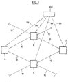
- the figure 1 very schematically represents a WDM optical network comprising four switching nodes A, B, C and D connected by optical links 10.
- a network management apparatus 100 is also provided, but this is not required .
- the number of nodes and the network topology of the figure 1 are chosen solely for the purposes of illustration and are not limiting in nature.
- the figure 2 schematically represents the architecture of a photonic node 1 that can be used to make the nodes A, B, C and D.
- the node1 has two input ports 2 and two output ports 3, intended to be connected to optical links 10.
- a broadcast-and-select transparent architecture based on wavelength selective switches (WSS) has been chosen for the illustration.
- WSS wavelength selective switches
- a wavelength selective switch designates a device that can be used as a reconfigurable multiplexer or as a reconfigurable demultiplexer.
- the selectable ports 4 serve as inputs and a common port 5 serves as the common output.
- the wavelength selective switch is capable of routing wavelength channels received at the respective inputs, selectively based on a control signal, to the common output of that equipment.
- This equipment thus performs a reconfigurable multiplexing function on wavelength channels whose optical frequencies are aligned on one or more predetermined grids. It can output a channel selected from the channels received on the inputs or an output multiplex consisting of a set of channels selected from the received channels. On each input port, you can send a channel, several channels or no channel.
- the switching of the channels within the wavelength selective switch is produced by spatial manipulation devices of the light, for example micromirrors actuated by MEMS microactuators or liquid crystal cells.
- these The devices are capable of adjusting the signal attenuation for each transmitted wavelength channel.
- the wavelength selection switches 20 of the node 1 serve both to select the wavelength channels to be transmitted to the ports 3 and to adjust their channel-to-channel output power.
- the attenuation level can be adjusted by altering the alignment of the reflected beam relative to an optimal alignment, so as to introduce losses corresponding to a misalignment or lack of alignment. focus chosen.
- the relationship between the microactuator control position or voltage and the resulting attenuation level can be calibrated and tabulated in a WSS memory for operation during operation.
- the incoming WDM signals are amplified by amplifiers 6 and diffused by type 1: 3 couplers 7 to the two WSSs 20 and an extraction device 30 respectively.
- Both WSS 20 also have an insertion port connected to an insertion device 40 via a coupler 8.
- the extraction device 30 serves to extract traffic at the node1. It comprises a wavelength selection switch 31 for selecting the channels to extract and adjust their output power, and a set of tunable optical receivers 32 connected to the output of the WSS 31 by a coupler 33. Other architectures are also possible.
- the insertion device 40 serves to insert traffic at the node1. It comprises a set of modulated tunable optical sources 41, a combiner 42 and an amplifier 43. Other architectures are also possible.
- the wavelength selection switches 20 and 31 are controlled by a control unit 11 of the node via control links 12.
- the control unit 11 performs several functions represented schematically by functional modules on the figure 2 .
- a control interface module 15 receives and transmits control messages on control channels 16, connected for example to a management apparatus network or other nodes in the network.
- the control channels can be transported in the same links as the data, for example on a dedicated wavelength, or on separate links of the data plane, for example on a control network superimposed on the data network.
- a connection management module 14 extracts control messages from the information concerning the connections already established or to establish or delete or modify and maintains a table of connections in a data storage 18 of the node 1.
- the connection table may contain various information relating to connections transmitted, received or passing through node 1, including origin, destination, traffic characteristics (throughput, quality of service) and allocated transport resources (ports, wavelengths, etc.).
- the connection management module 14 translates this information into switching instructions for a control module 19 which is responsible for producing the control signals of the WSSs on the links 12.
- An attenuation control module 17 exploits feedback signals 22 respectively representing the power spectrum of the signal WDM obtained at the output of each of the WSS 20.
- the attenuation control module 17 provides the control module 19 with instructions to attenuation control to adjust the power of each channel according to a predetermined desired power profile and power levels actually measured.
- a coupler 23 is placed at the output of each WSS 20 to pick up a small portion of the output signal and send it to a power measurement device of the channels 24.
- the power meter 24 measures a power spectrum of the wavelength channels it receives.
- the attenuation control module 17 compares this measured spectrum with a predetermined desired power profile, which is for example stored in a memory of the control unit 11.
- the desired power profile can have different shapes, for example a shape. substantially flat corresponding to equal powers for all channels, or a non-flat shape corresponding to a higher power in some parts of the spectrum and lower in other parts of the spectrum.
- a non-flat profile may in particular be chosen to compensate for a non-uniform gain curve of EDFA type optical amplifiers.
- a recovery connection here refers to a connection that is associated with a work connection and is scheduled to carry traffic from the work connection in the event of its failure.
- the recovery connection may be provided to recover the end-to-end work connection, in which case the source and destination nodes of the recovery connection are the source and destination nodes of the working connection.
- the recovery connection may be provided to recover a segment of the working connection, in which case the source node and / or the destination node of the recovery connection may be different from the source node and / or the destination of the working connection.
- a recovery connection is therefore not intended to carry traffic immediately upon establishment.
- the establishment of the recovery connection consists in fact of planning the recovery connection in the corresponding nodes, that is to say in the control plane of the nodes, so as to reserve transport resources, select these resources and prepare the activation of these resources.
- the recovery connection is kept in a latent state in which the allocated transport resources can be temporarily used to carry additional traffic.
- Activation of the recovery connection involves transmitting corresponding instructions to the nodes in a phase of activation of the connection. The transport resources can then be pre-empted to establish the recovery connection in the data plane and carry traffic instead of the working connection.
- control plane of the node is meant here all the elements, functionalities and protocols participating in the control of the network, in particular the functionalities provided by a GMPLS protocol stack, for example routing, signaling and traffic engineering.
- the data plane of the node designates all the elements, functions and protocols involved in the transfer and transport of the data.
- control plan and data plan is a logical distinction that does not necessarily correspond to separate physical elements.
- transport resource can cover different physical elements of the network depending on the transport technologies used.
- transport resources are the wavelengths, the input ports 2, the output ports 3, the optical sources 41 and the optical receivers 32.
- resources may also include memory space for queues, CPU time, time slots for TDM multiplexing, and so on.
- the recovery connection consists of a determined wavelength channel to be transmitted by node A, transparently transiting through node C and being received by node D.
- the manner of determining the route and the wavelength to use is not described here. Any known technique of routing and wavelength assignment can be used.
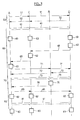
- a signaling phase 50 information concerning the recovery connection to be established is transmitted to the nodes A, C and D.
- the connection management module 14 thus updates the connection table to decide and memorize the connections. corresponding resource allocations.
- the nodes perform the necessary interconnections in the data plane, that is to say at the wavelength switches 20 and 31, to establish a photonic path between a source of the node A and a node. receiver node D.
- the node A begins to transmit a signal at the wavelength chosen to test the connection path, as represented by the arrows 61. This signal can be advantageously transmitted by the same optical source that is intended to serve in the working connection, or by another source.
- the attenuation control modules 17 of the nodes are then active to adjust the wavelength switches 20 and 31 to attenuation levels in accordance with the desired profiles (step 63). This setting which involves feedback may take some time to stabilize, for example one or a few seconds per node.
- the power settings of the length channel recovery connection wave can be sequentially performed node-to-node from the source node A to the destination node D. Alternatively these settings can be made in another order. Power settings can also be performed simultaneously at multiple points of the connection path. In addition to the attenuations produced by the wavelength-selective switches, these adjustments may also relate to other parameters of the components of the node, for example the power of the transponder 41 used in the source node A, the gain of the amplifier 43 , or the gain of a possible optical amplifier integrated in the receiver 32 used in the destination node D.
- the nodes memorize the settings of the WSS and other components thus obtained in association with an identifier of the recovery connection (step 62).
- the settings are stored in the connection table or in another data structure logically associated with the connection table, for example in the data storage 18 of the node or in a remote device.
- Such settings may be stored in various forms, for example as an attenuation or gain level or as a control signal level, eg electrical voltages applied to MEMS microactuators or amplification current applied to the optical source.
- the signal 61 is therefore interrupted and the corresponding transport resources are placed in a shared allocation state for a latency phase 70, ie until there is a need to use the recovery connection.
- the resources remain allocated to the recovery connection in the control plane, ie in the connection table of the node, but this allocation is not exclusive.
- the connection management module 14 can temporarily allocate these resources to carry other signals during the latency phase 70.
- the same resource can be simultaneously allocated to several recovery connections corresponding to different work connections. disjoint, in accordance with a shared-mesh restoration scheme.
- FIG. 3 there is shown a method of establishing the working connection during the latency phase 70.
- This establishment order allows the use during the test phase of the resources to be used subsequently for the working connection, for example the optical source of the work connection. nodeA and optical receiver of the nodeD. Alternatively, the establishment of the working connection could also be done earlier.
- an activation phase 80 the nodes A, C and D restore the recovery connection in the data plane to carry the traffic of the working connection, as represented by the arrows 81.
- the activation phase is for example triggered in response to detecting a failure of the working connection (step 75), a failure which is here represented at node B. If resources allocated to the recovery connection are carrying other connections, these resources are preempted at the time of the activation phase, so that these other connections must be interrupted or re-routed. However, this preemption mechanism can be regulated by connection priority rules.
- step 82 the control modules 19 restore the attenuation settings that were stored in step 62.
- the recovery connection is made operational very quickly, without the need to wait for stabilization of the feedback power control loops again. Since the memorized attenuation settings were obtained under actual transmission conditions during the test phase, they are very likely to correspond very substantially to the optimal settings. Thus, resetting the WSSs in this stored state makes it possible very quickly to receive the traffic 81 at the destination node D with good signal quality.
- the evolution of the traffic during the latency phase 70 slightly changes the optimal attenuation levels for the recovery connection, compared to the levels obtained. during the test phase.
- the stored adjustment states may become more out of date. Therefore, in one embodiment, it is intended to repeat the test phase at regular intervals to update the stored attenuation settings.
- the attenuation adjustment states obtained during the activity phase of the recovery connection are stored by the nodes, to serve as initial states during a next activation of the recovery connection.
- the stored control states can be kept up to date according to the evolution of the traffic in the network and the corresponding evolution of the optimal power levels.
- the execution of the method described above involves transmitting corresponding instructions to the nodes involved.
- these instructions are transmitted by signaling messages of the RSVP-TE protocol.
- the control interface module 15 of the nodes comprises an RSVP-TE signaling module.
- the source node A transmits an establishment request of LSP 51, ie a PATH message, containing an identifier of the LSP (LSP id) and various objects describing the connection to be established, explicit route, length (s) of available wave (s) (label set) and others.
- LSP id an identifier of the LSP
- various objects describing the connection to be established explicit route, length (s) of available wave (s) (label set) and others.
- the conventions outlined in the IETF guidelines can be used, including RFC 3473 and RFC 4872.
- the recovery LSP is set with the S (Secondary) bit enabled and the P (Protecting) bit enabled.
- a corresponding flag may be provided in the PATH message.
- this indicator may consist of one or more bits of the ADMIN STATUS object, in particular the T bit (Test) may be set to 1.
- the PATH message has passed from node to node along the connection path according to the known technique. If the connection of recovery can be established, the destination node D responds with a reservation message 52, ie a RESV message, which follows the reverse path according to the known technique.
- RSVP-TE messages can also be used.
- the destination node D triggers the end of the test phase when it determines that the optical signal of the test phase is received with a satisfactory and stable quality.
- a corresponding indicator can be provided in a RESV message 65 sent by the destination node D.
- this indicator can consist of one or more bits of the object ADMIN STATUS, in particular the bit T (Test ) This message is transmitted from node node to trigger each time step 62. At its reception, the source node A interrupts the optical signal 61.
- the RSVP-TE protocol can also be used to establish a working LSP using PATH and RESV messages.
- this step is schematically represented during phase 70 for a working LSP along the ABC route.
- the arrows 71 represent the PATH messages and the arrows 72 the RESV messages.
- the arrows 73 represent the traffic carried on the working LSP thus established.
- the arrow 76 represents a notification message of the RSVP-TE protocol used to warn the source node A of the existence of a failure of the working LSP, in order to trigger the activation of the recovery LSP. Other methods of fault reporting are also possible.
- the RSVP-TE protocol can also be used to activate the recovery LSP in response to the failure of the working LSP.
- the node A transmits for example a PATH message 85 containing the identifier of the recovery LSP (LSP id) and with the S bit (Secondary) disabled.
- the use of the RSVP-TE protocol is not the only way to coordinate the establishment of the recovery connection by the nodes.
- Other signaling or network management protocols may also be employed.
- the establishment of the recovery connection is entirely controlled by a network management apparatus 100 connected to the node by links 99, as visible on the figure 1 .
- the control interface module 15 of the nodes comprises a communication module adapted to the management apparatus 100.
- control unit 11 can comprise many other functions and modules, for example to control and configure optical transponders, optical receivers and other active elements of the node. In a particular embodiment, it comprises a whole GMPLS protocol stack. Moreover, although only one control unit has been shown, it is clear that the functions described can be distributed in several circuits, for example in the form of a high level controller for the node and several low level controllers. each dedicated to a WSS.
- the embodiments described above can easily be adapted to other node architectures, other types of signals, other switching techniques, especially in the electronic field, and other power modification devices.
- the document EP1161115 describes a node architecture in which the power adjustment is performed by variable optical attenuators or amplifiers.
- test phase of the recovery connection can be used to adjust other characteristics of the optical signal with the aid of corresponding devices, for example polarization, dispersion and others. It is also possible to process these settings in the same way as the power to speed up the activation of the recovery connection.
- control units can be made in different forms, unitarily or distributed, by means of hardware and / or software components.
- Useful hardware components are ASIC specific integrated circuits, FPGA programmable logic networks or microprocessors.
- Software components can be written in different programming languages, for example C, C ++, Java or VHDL. This list is not exhaustive.
- a network management apparatus may be hardware equipment, for example a microcomputer, a workstation, a device connected to the Internet or any other dedicated or general purpose communication device. Software programs run by this device perform network management functions to control network elements.
Landscapes
- Engineering & Computer Science (AREA)
- Computer Networks & Wireless Communication (AREA)
- Signal Processing (AREA)
- Optical Communication System (AREA)
Claims (16)
- Verfahren zum Aufbau einer Wiederherstellungsverbindung in einem optischen Netzwerk, die folgenden Schritte umfassend:das Zuteilen von optischen Transportressourcen für besagte Wiederherstellungsverbindung entlang eines Verbindungswegs,im Verlauf einer Testphase für besagte Wiederherstellungsverbindung (60) das Übermitteln eines optischen Signals (61) mittels besagter Transportressourcen entlang des Verbindungswegs und das Einstellen einer Modifizierungsvorrichtung für die Leistung des optischen Signals (20, 31),das Speichern (62) des Zustands der Einstellung besagter Leistungsmodifizierungsvorrichtung, die im Verlauf besagter Testphase für die Wiederherstellungsverbindung ermittelt wurde,das Unterbrechen der Übermittlung besagten optischen Signals am Ende der Testphase, im Verlauf einer Aktivierungsphase für die Wiederherstellungsverbindung (80) das Zurücksetzen (82) der Einstellung der Leistungsmodifizierungsvorrichtung des optischen Signals auf den gespeicherten Einstellungszustand und das neuerliche Übermitteln eines optischen Signals (81) mittels besagter optischer Transportressourcen entlang des Verbindungswegs.
- Verfahren nach Anspruch 1, den folgenden Schritt umfassend:das Mitteilen an mindestens einen auf besagtem Verbindungsweg situierten Kommunikationsknoten mindestens eines der Ereignisse aus der Gruppe, die gebildet wird vom Beginn der Testphase, dem Ende der Testphase und dem Beginn der Aktivierungsphase, was anhand einer Verwaltungsnachricht erfolgt, die von einer zentralen Netzverwaitungsvorrichtung (100) gesendet wird.
- Verfahren nach Anspruch 1 oder 2, den folgenden Schritt umfassend:das Mitteilen an mindestens einen auf besagtem Verbindungsweg situierten Kommunikationsknoten mindestens eines der Ereignisse aus der Gruppe, die gebildet wird vom Beginn der Testphase, dem Ende der Testphase und dem Beginn der Aktivierungsphase, was anhand von Signalisierungsnachrichten (51, 65, 85) erfolgt, die von den auf dem Verbindungsweg situierten Kommunikationsknoten ausgetauscht werden.
- Verfahren nach einem jeglichen der Ansprüche 1 bis 3, eine Latenzphase (70) der Wiederherstellungsverbindung zwischen der Testphase (60) und der Aktivierungsphase (80) umfassend, im Verlauf derer die der besagten Wiederherstellungsverbindung zugewiesenen, optischen Transportressourcen assoziiert sind mit einem geteilten Zuweisungszustand, welcher die Benutzung besagter Ressourcen für andere Verbindungen autorisiert.
- Verfahren nach einem jeglichen der Ansprüche 1 bis 4, wobei der Schritt des Regulierens der Leistungsmodifizierungsvorrichtung des optischen Signals in Funktion eines vordefinierten, erwünschten Leistungsprofils und eines Rückkopplungssignals (22) erfolgt, welches sensitiv für die tatsächlich übertragene, der Leistungsmodifizierungsvorrichtung nachgelagerte Leistung des optischen Signals ist.
- Verfahren nach Anspruch 5, wobei das optische Signal im Wellenlängenmultiplexverfahren übermittelt wird, wobei das besagte, vordefinierte erwünschte Leistungsprofil ein Verhältnis zwischen der jeweiligen Leistung der verschiedenen Wellenlängenmultiplexkanäle umfasst.
- Verfahren nach einem jeglichen der Ansprüche 1 bis 6, wobei die Leistungsmodifizierungsvorrichtung des optischen Signals zu der Gruppe gehört, die von den optischen variablen Abschwächern, den optischen Verstärkern, den Wellenlängenauswahlschaltern (20, 31), den Wellenlängenblockierern und den Spektralentzerrern gebildet wird.
- Verfahren nach einem jeglichen der Ansprüche 1 bis 7, wobei die Wiederherstellungsverbindung im photonischen Bereich erfolgt.
- Element eines optischen Netzwerks (1), umfassend:einer Wiederherstellungsverbindung zugewiesene, optische Transportressourcen für den Transport eines optischen Signals (61) besagter Wiederherstellungsverbindung, eine Leistungsmodifizierungsvorrichtung (20, 31) zum Modifizieren der Leistung besagten optischen Signals undSteuerungsmittel (11), ausgelegt für das Einstellen besagter Leistungsmodifizierungsvorrichtung für das optische Signal, für das Speichern von im Verlauf der Testphase besagter Wiederherstellungsverbindung gewonnener Zustandsdaten zur Einstellung besagter Leistungsmodifizierungsvorrichtung in einer Speichervorrichtung und für das Zurücksetzen der Einstellung der Leistungsmodifizierungsvorrichtung auf den Einstellungszustand, der in einer Aktivierungsphase für die Wiederherstellungsverbindung gespeichert wurde.
- Element eines optischen Netzwerks nach Anspruch 9, ein Kommunikationsmodul (15) für den Empfang von Verwaltungsnachrichten umfassend, die von einer zentralen Netzverwaltungsvorrichtung (100) gesendet werden, dergestalt, dass anhand besagter Verwaltungsnachrichten eine Benachrichtigung hinsichtlich mindestens eines Ereignisses aus der Gruppe empfangen wird, welche gebildet wird vom Beginn der Testphase, dem Ende der Testphase und dem Beginn der Aktivierungsphase.
- Element eines optischen Netzwerks nach Anspruch 9, ein Kommunikationsmodul (15) für den Empfang von Verwaltungsnachrichten umfassend, die von einer zentralen Netzverwaltungsvorrichtung (100) gesendet werden, dergestalt, dass anhand besagter Verwaltungsnachrichten eine Benachrichtigung hinsichtlich mindestens eines Ereignisses aus der Gruppe empfangen wird, welche gebildet wird vom Beginn der Testphase, dem Ende der Testphase und dem Beginn der Aktivierungsphase.
- Element eines optischen Netzwerks nach einem jeglichen der Ansprüche 9 bis 11, wobei besagte Steuerungsmittel ausgelegt sind für das Speichern von Zuweisungszuständen optischer Transportressourcen des Netzwerkelements, wobei besagte Zuweisungszustände die Bedingungen für die Benutzung besagter Ressourcen für Verbindungen definieren, wobei besagte Steuerungsmittel dafür ausgelegt sind, um den Zuweisungszustand optischer Transportressourcen zu ändern, die besagter Wiederherstellungsverbindung zu Beginn der Aktivierungsphase zugewiesen sind, um so vor der Aktivierungsphase eine Benutzung besagter Ressourcen durch andere Verbindungen zu autorisieren und besagte Benutzung während der Aktivierungsphase zu unterbinden.
- Element eines optischen Netzwerks nach einem jeglichen der Ansprüche 9 bis 12, eine Messvorrichtung (24) umfassend, welche sensitiv für die tatsächlich übertragene, der Leistungsmodifizierungsvorrichtung nachgelagerte Leistung des optischen Signals ist, uns wobei besagte Steuerungsmittel ausgelegt sind für das Einstellen der Leistungsmodifizierungsvorrichtung des optischen Signals in Funktion eines vordefinierten, erwünschten Leistungsprofils und eines Rückkopplungssignals (22), welches von besagter Messvorrichtung erzeugt wird.
- Element eines optischen Netzwerks nach Anspruch 13, wobei das optische Signal im Wellenlängenmultiplexverfahren übermittelt wird, wobei das besagte, vordefinierte erwünschte Leistungsprofil ein Verhältnis zwischen der jeweiligen Leistung der verschiedenen Wellenlängenmultiplexkanäle umfasst.
- Element eines optischen Netzwerks nach einem jeglichen der Ansprüche 9 bis 14, wobei die Leistungsmodifizierungsvorrichtung des optischen Signals zu der Gruppe gehört, die von den optischen variablen Abschwächern, den optischen Verstärkern, den Wellenlängenauswahlschaltern (20, 31) und den Wellenlängenblockierern gebildet wird.
- Element eines optischen Netzwerks nach einem jeglichen der Ansprüche 9 bis 14, wobei die Leistungsmodifizierungsvorrichtung des optischen Signals in eine optische Quelle oder einen optischen Empfänger integriert ist.
Applications Claiming Priority (1)
| Application Number | Priority Date | Filing Date | Title |
|---|---|---|---|
| FR0760073A FR2925821B1 (fr) | 2007-12-20 | 2007-12-20 | Procede pour etablir une connexion de recuperation dans un reseau optique |
Publications (3)
| Publication Number | Publication Date |
|---|---|
| EP2073566A2 EP2073566A2 (de) | 2009-06-24 |
| EP2073566A3 EP2073566A3 (de) | 2016-04-27 |
| EP2073566B1 true EP2073566B1 (de) | 2016-11-16 |
Family
ID=39760501
Family Applications (1)
| Application Number | Title | Priority Date | Filing Date |
|---|---|---|---|
| EP08170414.0A Not-in-force EP2073566B1 (de) | 2007-12-20 | 2008-12-02 | Verfahren zur Herstellung einer Verbindung zur Rückgewinnung in einem optischen Netz |
Country Status (2)
| Country | Link |
|---|---|
| EP (1) | EP2073566B1 (de) |
| FR (1) | FR2925821B1 (de) |
Families Citing this family (1)
| Publication number | Priority date | Publication date | Assignee | Title |
|---|---|---|---|---|
| CN114173224B (zh) * | 2021-11-03 | 2023-09-26 | 烽火通信科技股份有限公司 | 光线路调整方法、装置、设备及存储介质 |
Family Cites Families (3)
| Publication number | Priority date | Publication date | Assignee | Title |
|---|---|---|---|---|
| US7542675B1 (en) | 2000-05-30 | 2009-06-02 | Nortel Networks Limited | Optical switch with power equalization |
| US20030117950A1 (en) * | 2001-12-26 | 2003-06-26 | Huang Gail G | Link redial for mesh protection |
| JP4878479B2 (ja) * | 2006-02-01 | 2012-02-15 | 株式会社日立製作所 | 光クロスコネクト装置 |
-
2007
- 2007-12-20 FR FR0760073A patent/FR2925821B1/fr not_active Expired - Fee Related
-
2008
- 2008-12-02 EP EP08170414.0A patent/EP2073566B1/de not_active Not-in-force
Non-Patent Citations (1)
| Title |
|---|
| None * |
Also Published As
| Publication number | Publication date |
|---|---|
| FR2925821A1 (fr) | 2009-06-26 |
| EP2073566A2 (de) | 2009-06-24 |
| FR2925821B1 (fr) | 2009-12-11 |
| EP2073566A3 (de) | 2016-04-27 |
Similar Documents
| Publication | Publication Date | Title |
|---|---|---|
| EP2086248B1 (de) | Verfahren zur Kontrolle der Herstellung einer Verbindung in einem optischen Netz | |
| EP2279586B1 (de) | Schutzverfahren in einem kommunikationsnetzwerk im verbindungsmodus einer punkt-zu-mehrpunkt-primärhierarchie | |
| EP2070382B1 (de) | Verfahren zur verwaltung von verbindungen in einem optischen zugangsnetzwerk sowie plattform, vermittlungsstelle, netzwerk und computerprogrammprodukt dafür | |
| FR2759834A1 (fr) | Reseau de transmission en anneau reconfigurable avec multiplexage en longueur d'onde pour liaisons semi-permanentes | |
| EP2484122A1 (de) | Optische paketvermittlungsvorrichtung | |
| EP0933895A1 (de) | Verfahren zur Detektion eines or mehrerer freien Kanäle in einem optischen Multiplexsignal, eine Vorrichtung zur Ausführung und eine Anwendung der Vorrichtung | |
| EP2073566B1 (de) | Verfahren zur Herstellung einer Verbindung zur Rückgewinnung in einem optischen Netz | |
| EP1428333B1 (de) | Optisches ringnetzwerk mit doppeltem optischem bus | |
| EP2606655B1 (de) | Verfahren zur umschaltung eines optischen datenstroms, computerprogrammprodukt sowie zugehörige speichervorrichtung und knoten | |
| FR2958490A1 (fr) | Procede pour controler l'etablissement d'une connexion dans un reseau de transport | |
| EP1592159B1 (de) | Optisches Übertragungsnetz mit Baumstruktur | |
| WO2019158861A1 (fr) | Plan de commande pour un réseau optique de transmission de rafales multi-porteuses de données à adaptation dynamique de séquence d'apprentissage | |
| EP2200204B1 (de) | Signalisierung zur Herstellung einer Verbindung in einem optischen Netzwerk | |
| FR2996973A1 (de) | ||
| EP2549773B1 (de) | Vorrichtung und Verfahren zum Vermischen von mit einer Wellenlänge assoziierten optischen Komponenten zu einer gemischten optischen Komponente | |
| EP1193995A1 (de) | Koppelfeld für ein optischen WDM Netzwerk | |
| EP3545631B1 (de) | Bestimmung von regenerativen relaisknoten in einer übertragungsleitung eines optischen netzwerks | |
| EP4489328A1 (de) | Verfahren und vorrichtung zur verwaltung eines betriebsfehlers einer laserdiode | |
| EP2238718B1 (de) | Technik zum schutz eines pfads mit umschaltungen von tags im verbundenen modus während eines einen gegebenen knoten des pfades beeinträchtigenden fehlers | |
| Fei | Impacts of physical layer impairments on optical network performance | |
| EP1804407B1 (de) | Accessknoten für optisches Ringnetzwerk | |
| EP1901099B1 (de) | Schaltmodul für optische Wellenlängen | |
| EP1906574B1 (de) | Verfahren zur Steuerung eines gemeinsamen Schutzmoduls und Vorrichtung zur Verarbeitung von optischen Wellenlängen | |
| FR2988542A1 (fr) | Dispositif et procede de fusion de composantes optiques associees a une longueur d'onde en une composante optique fusionnee | |
| FR2978314A1 (fr) | Dispositif et procede de fusion de composantes optiques associees a une longueur d'onde en une composante optique fusionnee |
Legal Events
| Date | Code | Title | Description |
|---|---|---|---|
| PUAI | Public reference made under article 153(3) epc to a published international application that has entered the european phase |
Free format text: ORIGINAL CODE: 0009012 |
|
| AK | Designated contracting states |
Kind code of ref document: A2 Designated state(s): AT BE BG CH CY CZ DE DK EE ES FI FR GB GR HR HU IE IS IT LI LT LU LV MC MT NL NO PL PT RO SE SI SK TR |
|
| AX | Request for extension of the european patent |
Extension state: AL BA MK RS |
|
| RAP1 | Party data changed (applicant data changed or rights of an application transferred) |
Owner name: ALCATEL LUCENT |
|
| 111Z | Information provided on other rights and legal means of execution |
Free format text: AT BE BG CH CY CZ DE DK EE ES FI FR GB GR HR HU IE IS IT LI LT LU LV MC MT NL NO PL PT RO SE SI SK TR Effective date: 20130410 |
|
| RAP1 | Party data changed (applicant data changed or rights of an application transferred) |
Owner name: ALCATEL LUCENT |
|
| D11X | Information provided on other rights and legal means of execution (deleted) | ||
| PUAL | Search report despatched |
Free format text: ORIGINAL CODE: 0009013 |
|
| AK | Designated contracting states |
Kind code of ref document: A3 Designated state(s): AT BE BG CH CY CZ DE DK EE ES FI FR GB GR HR HU IE IS IT LI LT LU LV MC MT NL NO PL PT RO SE SI SK TR |
|
| AX | Request for extension of the european patent |
Extension state: AL BA MK RS |
|
| RIC1 | Information provided on ipc code assigned before grant |
Ipc: H04L 12/56 00000000ALI20160322BHEP Ipc: H04Q 11/00 20060101AFI20160322BHEP Ipc: H04J 14/02 20060101ALI20160322BHEP |
|
| 17P | Request for examination filed |
Effective date: 20160531 |
|
| RBV | Designated contracting states (corrected) |
Designated state(s): AT BE BG CH CY CZ DE DK EE ES FI FR GB GR HR HU IE IS IT LI LT LU LV MC MT NL NO PL PT RO SE SI SK TR |
|
| GRAP | Despatch of communication of intention to grant a patent |
Free format text: ORIGINAL CODE: EPIDOSNIGR1 |
|
| RIC1 | Information provided on ipc code assigned before grant |
Ipc: H04L 12/701 20130101ALI20160617BHEP Ipc: H04Q 11/00 20060101AFI20160617BHEP Ipc: H04J 14/02 20060101ALI20160617BHEP |
|
| INTG | Intention to grant announced |
Effective date: 20160715 |
|
| GRAS | Grant fee paid |
Free format text: ORIGINAL CODE: EPIDOSNIGR3 |
|
| GRAA | (expected) grant |
Free format text: ORIGINAL CODE: 0009210 |
|
| AK | Designated contracting states |
Kind code of ref document: B1 Designated state(s): AT BE BG CH CY CZ DE DK EE ES FI FR GB GR HR HU IE IS IT LI LT LU LV MC MT NL NO PL PT RO SE SI SK TR |
|
| REG | Reference to a national code |
Ref country code: GB Ref legal event code: FG4D Free format text: NOT ENGLISH |
|
| REG | Reference to a national code |
Ref country code: CH Ref legal event code: EP |
|
| REG | Reference to a national code |
Ref country code: IE Ref legal event code: FG4D Free format text: LANGUAGE OF EP DOCUMENT: FRENCH |
|
| REG | Reference to a national code |
Ref country code: AT Ref legal event code: REF Ref document number: 846894 Country of ref document: AT Kind code of ref document: T Effective date: 20161215 |
|
| REG | Reference to a national code |
Ref country code: FR Ref legal event code: PLFP Year of fee payment: 9 |
|
| REG | Reference to a national code |
Ref country code: DE Ref legal event code: R096 Ref document number: 602008047367 Country of ref document: DE |
|
| REG | Reference to a national code |
Ref country code: DE Ref legal event code: R096 Ref document number: 602008047367 Country of ref document: DE |
|
| AKX | Designation fees paid |
Designated state(s): AT BE BG CH CY CZ DE DK EE ES FI FR GB GR HR HU IE IS IT LI LT LU LV MC MT NL NO PL PT RO SE SI SK TR |
|
| PG25 | Lapsed in a contracting state [announced via postgrant information from national office to epo] |
Ref country code: LV Free format text: LAPSE BECAUSE OF FAILURE TO SUBMIT A TRANSLATION OF THE DESCRIPTION OR TO PAY THE FEE WITHIN THE PRESCRIBED TIME-LIMIT Effective date: 20161116 |
|
| PGFP | Annual fee paid to national office [announced via postgrant information from national office to epo] |
Ref country code: FR Payment date: 20161222 Year of fee payment: 9 |
|
| REG | Reference to a national code |
Ref country code: NL Ref legal event code: MP Effective date: 20161116 |
|
| REG | Reference to a national code |
Ref country code: LT Ref legal event code: MG4D |
|
| REG | Reference to a national code |
Ref country code: AT Ref legal event code: MK05 Ref document number: 846894 Country of ref document: AT Kind code of ref document: T Effective date: 20161116 |
|
| PG25 | Lapsed in a contracting state [announced via postgrant information from national office to epo] |
Ref country code: LT Free format text: LAPSE BECAUSE OF FAILURE TO SUBMIT A TRANSLATION OF THE DESCRIPTION OR TO PAY THE FEE WITHIN THE PRESCRIBED TIME-LIMIT Effective date: 20161116 Ref country code: GR Free format text: LAPSE BECAUSE OF FAILURE TO SUBMIT A TRANSLATION OF THE DESCRIPTION OR TO PAY THE FEE WITHIN THE PRESCRIBED TIME-LIMIT Effective date: 20170217 Ref country code: SE Free format text: LAPSE BECAUSE OF FAILURE TO SUBMIT A TRANSLATION OF THE DESCRIPTION OR TO PAY THE FEE WITHIN THE PRESCRIBED TIME-LIMIT Effective date: 20161116 Ref country code: NL Free format text: LAPSE BECAUSE OF FAILURE TO SUBMIT A TRANSLATION OF THE DESCRIPTION OR TO PAY THE FEE WITHIN THE PRESCRIBED TIME-LIMIT Effective date: 20161116 Ref country code: NO Free format text: LAPSE BECAUSE OF FAILURE TO SUBMIT A TRANSLATION OF THE DESCRIPTION OR TO PAY THE FEE WITHIN THE PRESCRIBED TIME-LIMIT Effective date: 20170216 |
|
| PG25 | Lapsed in a contracting state [announced via postgrant information from national office to epo] |
Ref country code: ES Free format text: LAPSE BECAUSE OF FAILURE TO SUBMIT A TRANSLATION OF THE DESCRIPTION OR TO PAY THE FEE WITHIN THE PRESCRIBED TIME-LIMIT Effective date: 20161116 Ref country code: BE Free format text: LAPSE BECAUSE OF NON-PAYMENT OF DUE FEES Effective date: 20161231 Ref country code: PT Free format text: LAPSE BECAUSE OF FAILURE TO SUBMIT A TRANSLATION OF THE DESCRIPTION OR TO PAY THE FEE WITHIN THE PRESCRIBED TIME-LIMIT Effective date: 20170316 Ref country code: AT Free format text: LAPSE BECAUSE OF FAILURE TO SUBMIT A TRANSLATION OF THE DESCRIPTION OR TO PAY THE FEE WITHIN THE PRESCRIBED TIME-LIMIT Effective date: 20161116 Ref country code: FI Free format text: LAPSE BECAUSE OF FAILURE TO SUBMIT A TRANSLATION OF THE DESCRIPTION OR TO PAY THE FEE WITHIN THE PRESCRIBED TIME-LIMIT Effective date: 20161116 Ref country code: PL Free format text: LAPSE BECAUSE OF FAILURE TO SUBMIT A TRANSLATION OF THE DESCRIPTION OR TO PAY THE FEE WITHIN THE PRESCRIBED TIME-LIMIT Effective date: 20161116 Ref country code: HR Free format text: LAPSE BECAUSE OF FAILURE TO SUBMIT A TRANSLATION OF THE DESCRIPTION OR TO PAY THE FEE WITHIN THE PRESCRIBED TIME-LIMIT Effective date: 20161116 |
|
| PG25 | Lapsed in a contracting state [announced via postgrant information from national office to epo] |
Ref country code: DK Free format text: LAPSE BECAUSE OF FAILURE TO SUBMIT A TRANSLATION OF THE DESCRIPTION OR TO PAY THE FEE WITHIN THE PRESCRIBED TIME-LIMIT Effective date: 20161116 Ref country code: RO Free format text: LAPSE BECAUSE OF FAILURE TO SUBMIT A TRANSLATION OF THE DESCRIPTION OR TO PAY THE FEE WITHIN THE PRESCRIBED TIME-LIMIT Effective date: 20161116 Ref country code: CZ Free format text: LAPSE BECAUSE OF FAILURE TO SUBMIT A TRANSLATION OF THE DESCRIPTION OR TO PAY THE FEE WITHIN THE PRESCRIBED TIME-LIMIT Effective date: 20161116 Ref country code: EE Free format text: LAPSE BECAUSE OF FAILURE TO SUBMIT A TRANSLATION OF THE DESCRIPTION OR TO PAY THE FEE WITHIN THE PRESCRIBED TIME-LIMIT Effective date: 20161116 Ref country code: SK Free format text: LAPSE BECAUSE OF FAILURE TO SUBMIT A TRANSLATION OF THE DESCRIPTION OR TO PAY THE FEE WITHIN THE PRESCRIBED TIME-LIMIT Effective date: 20161116 |
|
| REG | Reference to a national code |
Ref country code: CH Ref legal event code: PL |
|
| REG | Reference to a national code |
Ref country code: DE Ref legal event code: R097 Ref document number: 602008047367 Country of ref document: DE |
|
| PG25 | Lapsed in a contracting state [announced via postgrant information from national office to epo] |
Ref country code: IT Free format text: LAPSE BECAUSE OF FAILURE TO SUBMIT A TRANSLATION OF THE DESCRIPTION OR TO PAY THE FEE WITHIN THE PRESCRIBED TIME-LIMIT Effective date: 20161116 Ref country code: BG Free format text: LAPSE BECAUSE OF FAILURE TO SUBMIT A TRANSLATION OF THE DESCRIPTION OR TO PAY THE FEE WITHIN THE PRESCRIBED TIME-LIMIT Effective date: 20170216 |
|
| PLBE | No opposition filed within time limit |
Free format text: ORIGINAL CODE: 0009261 |
|
| STAA | Information on the status of an ep patent application or granted ep patent |
Free format text: STATUS: NO OPPOSITION FILED WITHIN TIME LIMIT |
|
| PG25 | Lapsed in a contracting state [announced via postgrant information from national office to epo] |
Ref country code: MC Free format text: LAPSE BECAUSE OF FAILURE TO SUBMIT A TRANSLATION OF THE DESCRIPTION OR TO PAY THE FEE WITHIN THE PRESCRIBED TIME-LIMIT Effective date: 20161116 |
|
| REG | Reference to a national code |
Ref country code: IE Ref legal event code: MM4A |
|
| 26N | No opposition filed |
Effective date: 20170817 |
|
| PG25 | Lapsed in a contracting state [announced via postgrant information from national office to epo] |
Ref country code: LU Free format text: LAPSE BECAUSE OF NON-PAYMENT OF DUE FEES Effective date: 20161202 Ref country code: LI Free format text: LAPSE BECAUSE OF NON-PAYMENT OF DUE FEES Effective date: 20161231 Ref country code: CH Free format text: LAPSE BECAUSE OF NON-PAYMENT OF DUE FEES Effective date: 20161231 |
|
| PG25 | Lapsed in a contracting state [announced via postgrant information from national office to epo] |
Ref country code: SI Free format text: LAPSE BECAUSE OF FAILURE TO SUBMIT A TRANSLATION OF THE DESCRIPTION OR TO PAY THE FEE WITHIN THE PRESCRIBED TIME-LIMIT Effective date: 20161116 Ref country code: IE Free format text: LAPSE BECAUSE OF NON-PAYMENT OF DUE FEES Effective date: 20161202 |
|
| PGFP | Annual fee paid to national office [announced via postgrant information from national office to epo] |
Ref country code: DE Payment date: 20171211 Year of fee payment: 10 |
|
| REG | Reference to a national code |
Ref country code: BE Ref legal event code: MM Effective date: 20161231 |
|
| PGFP | Annual fee paid to national office [announced via postgrant information from national office to epo] |
Ref country code: GB Payment date: 20171221 Year of fee payment: 10 |
|
| PG25 | Lapsed in a contracting state [announced via postgrant information from national office to epo] |
Ref country code: HU Free format text: LAPSE BECAUSE OF FAILURE TO SUBMIT A TRANSLATION OF THE DESCRIPTION OR TO PAY THE FEE WITHIN THE PRESCRIBED TIME-LIMIT; INVALID AB INITIO Effective date: 20081202 Ref country code: CY Free format text: LAPSE BECAUSE OF FAILURE TO SUBMIT A TRANSLATION OF THE DESCRIPTION OR TO PAY THE FEE WITHIN THE PRESCRIBED TIME-LIMIT Effective date: 20161116 |
|
| PG25 | Lapsed in a contracting state [announced via postgrant information from national office to epo] |
Ref country code: IS Free format text: LAPSE BECAUSE OF FAILURE TO SUBMIT A TRANSLATION OF THE DESCRIPTION OR TO PAY THE FEE WITHIN THE PRESCRIBED TIME-LIMIT Effective date: 20161116 Ref country code: TR Free format text: LAPSE BECAUSE OF FAILURE TO SUBMIT A TRANSLATION OF THE DESCRIPTION OR TO PAY THE FEE WITHIN THE PRESCRIBED TIME-LIMIT Effective date: 20161116 |
|
| PG25 | Lapsed in a contracting state [announced via postgrant information from national office to epo] |
Ref country code: MT Free format text: LAPSE BECAUSE OF FAILURE TO SUBMIT A TRANSLATION OF THE DESCRIPTION OR TO PAY THE FEE WITHIN THE PRESCRIBED TIME-LIMIT Effective date: 20161116 |
|
| REG | Reference to a national code |
Ref country code: FR Ref legal event code: ST Effective date: 20180831 |
|
| PG25 | Lapsed in a contracting state [announced via postgrant information from national office to epo] |
Ref country code: FR Free format text: LAPSE BECAUSE OF NON-PAYMENT OF DUE FEES Effective date: 20180102 |
|
| REG | Reference to a national code |
Ref country code: DE Ref legal event code: R082 Ref document number: 602008047367 Country of ref document: DE Representative=s name: MENZIETTI WETZEL, DE Ref country code: DE Ref legal event code: R081 Ref document number: 602008047367 Country of ref document: DE Owner name: PROVENANCE ASSET GROUP LLC, PITTSFORD, US Free format text: FORMER OWNER: ALCATEL LUCENT, BOULOGNE BILLANCOURT, FR |
|
| REG | Reference to a national code |
Ref country code: GB Ref legal event code: 732E Free format text: REGISTERED BETWEEN 20190418 AND 20190426 |
|
| REG | Reference to a national code |
Ref country code: DE Ref legal event code: R119 Ref document number: 602008047367 Country of ref document: DE |
|
| GBPC | Gb: european patent ceased through non-payment of renewal fee |
Effective date: 20181202 |
|
| PG25 | Lapsed in a contracting state [announced via postgrant information from national office to epo] |
Ref country code: DE Free format text: LAPSE BECAUSE OF NON-PAYMENT OF DUE FEES Effective date: 20190702 |
|
| PG25 | Lapsed in a contracting state [announced via postgrant information from national office to epo] |
Ref country code: GB Free format text: LAPSE BECAUSE OF NON-PAYMENT OF DUE FEES Effective date: 20181202 |