EP2073584A1 - Systèmes de communication - Google Patents
Systèmes de communication Download PDFInfo
- Publication number
- EP2073584A1 EP2073584A1 EP20080171673 EP08171673A EP2073584A1 EP 2073584 A1 EP2073584 A1 EP 2073584A1 EP 20080171673 EP20080171673 EP 20080171673 EP 08171673 A EP08171673 A EP 08171673A EP 2073584 A1 EP2073584 A1 EP 2073584A1
- Authority
- EP
- European Patent Office
- Prior art keywords
- exclusion zone
- wireless communications
- communications system
- interference
- size
- Prior art date
- Legal status (The legal status is an assumption and is not a legal conclusion. Google has not performed a legal analysis and makes no representation as to the accuracy of the status listed.)
- Withdrawn
Links
Images
















Classifications
-
- H—ELECTRICITY
- H04—ELECTRIC COMMUNICATION TECHNIQUE
- H04W—WIRELESS COMMUNICATION NETWORKS
- H04W16/00—Network planning, e.g. coverage or traffic planning tools; Network deployment, e.g. resource partitioning or cells structures
- H04W16/14—Spectrum sharing arrangements between different networks
-
- H—ELECTRICITY
- H04—ELECTRIC COMMUNICATION TECHNIQUE
- H04W—WIRELESS COMMUNICATION NETWORKS
- H04W48/00—Access restriction; Network selection; Access point selection
- H04W48/02—Access restriction performed under specific conditions
- H04W48/04—Access restriction performed under specific conditions based on user or terminal location or mobility data, e.g. moving direction, speed
Definitions
- the invention relates to a method of, and apparatus for, reducing interference in a first wireless communications system; to a method of operating a controller for use with a first wireless communications system, and to the controller itself; and to a method of, and apparatus for, interacting with a first wireless communications system.
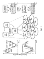
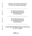
- Previously-considered methods for flexible use of spectrum include four different levels of spectrum management techniques in three different time scales: Spectrum Sharing and Coexistence (a couple of hours or days), Long Term (LT) Spectrum Assignment (a couple of minutes), Short Term (ST) Spectrum Assignment (one second) and fast dynamic Channel Allocation (10 ms time scale or even below).
- One of the entities included in this method is the concept of a gateway, which provides for long term spectrum assignment and some radio resource management (RRM) algorithms.
- RRM radio resource management
- LT Spectrum Assignment and ST Spectrum Assignment are responsible for defining the amount of spectrum available at common spectrum pool and shaping the boundaries of spectrum in a longer time scale
- dynamic Channel Allocation divides the final available spectrum determined by ST Spectrum Assignment (e.g. just borrowed from another cell) into radio sub-channels and decides which radio sub-channel would be allocated to which radio entity on a fast "ms" basis in response to radio channel and traffic variation.
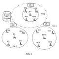
- an exclusion zone has been considered, as shown in Figure 3 .
- spectrum sharing or flexible use of spectrum is forbidden to avoid interference from one system to another.
- the exclusion zone may provide for protection of a satellite receiver as a primary system.
- a method of reducing interference in a first wireless communications system the first wireless communications system being operable in use to take part in a spectrum assignment process involving at least a second wireless communications system, the method comprising defining an exclusion zone in proximity to the first wireless communications system, the exclusion zone indicating that any mobile communications apparatus located within the exclusion zone is not permitted to communicate with the second wireless communications system using a portion of spectrum which was pre-assigned to the first wireless communications system and which is currently re-assigned to the second wireless communications system as part of the spectrum assignment process; and dynamically varying the size of the exclusion zone in dependence on a level of interference inflicted on the first wireless communications system.
- the spectrum assignment process may comprise the re-assignment of a portion of a spectrum band which has been pre-assigned to one of the first and second wireless communications systems from the one wireless communications system to the other of the first and second wireless communications systems.
- the spectrum assignment process may comprise (for example during negotiations between the first and second wireless communications systems) reassigning, from one of the first and second wireless communications systems to the other of the first and second wireless communications systems, some or all of the respective first or second pre-assigned spectrum band.
- pre-assigned it may be meant that the wireless communications system to which the spectrum band has been pre-assigned is licensed for operation within that spectrum band.
- any mobile communications apparatus in communication with one of the first and second wireless communications systems is permitted to operate only within the spectrum band which has been pre-assigned to the one wireless communications system, and is not permitted to operate within a portion of a spectrum band which has been re-assigned to the one wireless communications system from another wireless communications system as part of the spectrum assignment process.
- the mobile communications apparatus may operate within the spectrum band which has been pre-assigned to the wireless communications system with which the mobile communications apparatus is in communication, and/or within a portion of a spectrum band which has been re-assigned to that wireless communications system from another wireless communications system as part of the spectrum assignment process.
- flexible spectrum sharing may take place outside of the exclusion zone, but not within the exclusion zone.
- the first and second wireless communications systems may be radio access networks (RANs) operating within the radio frequency range of the electromagnetic spectrum.
- RANs radio access networks
- the wireless communications systems may operate within a microwave frequency range, for example.
- wireless communications system may relate to a wireless access network, for example a radio access network (RAN), including all of the elements of the network, for example base stations. Additionally or alternatively, it may relate to communications apparatus, for example a network element, e.g. a base station. In another arrangement, it may relate to an RFID tag reader, to a sink or wireless sensor network base station, or to a group of such readers forming a network, possibly including other equipment, e.g. control circuitry.
- RAN radio access network
- communications apparatus for example a network element, e.g. a base station.
- RFID tag reader to a sink or wireless sensor network base station, or to a group of such readers forming a network, possibly including other equipment, e.g. control circuitry.
- the term “mobile communications apparatus” may relate to wireless equipment which is capable of undertaking wireless communications with one or both of the wireless communications systems.
- the term may relate to user equipment (user-portable wireless equipment), for example a mobile telephone, personal digital assistant, laptop or PC, to an RFID tag/node or wireless sensor node.
- the exclusion zone is located in proximity to the first wireless communications system in order to protect that system from interference caused by the use of re-assigned portions of spectrum, as described above.
- the exclusion zone may fully or partially surround the first wireless communications system.
- it may surround a wireless access network as a whole, or it may surround a part of the first wireless communications system, e.g. a network element (for example a base station) of a wireless access network.
- a network element for example a base station
- the exclusion zone is located adjacent the first wireless communications system, or in any area from where wireless communication between the mobile communications apparatus and the second wireless communications system (using a portion of spectrum assigned from the first wireless communication system) is likely to inflict interference on the first wireless communications system.
- the method may provide for intelligent exclusion zone adjustments in a spectrum sharing scenario, providing means to assist spectrum sharing and co-existence among multiple systems, and providing interference protection to the first wireless communications system whilst allowing sharing of the same spectrum in surrounding geographical areas.
- the first wireless communications system may be arranged to communicate with an exclusion zone controller.
- the exclusion zone controller may form part of the first wireless communications system.
- a request for a change in the size of the exclusion zone may come from the first wireless communications system, the second wireless communications system, or the exclusion zone controller. For example, when the first wireless communications system is heavily loaded and in red (i.e. high interference), it may request the exclusion zone controller for an expansion of the exclusion zone in order to reduce interference, as an impact of the spectrum sharing process for the systems outside.
- the exclusion zone controller may get in touch with the second wireless communications system and may perform exclusion zone adjustments in response to a request from the second wireless communications system, leading to overall better traffic management in a system having multiple wireless communications systems.
- the shrinking exclusion zone may make it possible for the second wireless communications system to exploit higher transmission powers in the shared spectrum band leading to better QoS (Quality of Service) in the second wireless communications system.
- the invention may provide benefits for network operators. For example, the invention may improve the revenue for the borrowing party by making sure that the wireless resource is available when needed in peak times, and may provide an extra source of income for operators as the lending party by making sure that the redundant spectrum is not wasted and can be employed in an efficient way.
- the technical solution provided by the invention may improve the way spectrum is being managed in current legacy networks, and reduce the time required to tailor new services to network operators.
- the invention opens the way for a much better flexible exploitation of radio spectrum resources in a wireless network while significantly improving the spectrum efficiency and availability.
- the invention provides for more flexible use of spectrum, improved QoS, improved overall network coverage, reduced delivery delay, increased throughput, and reduced potential for call blockage, especially at cell edges. It may simultaneously improve overall radio sub-channel utilisation while improving the interference level, and provide effective means to improve interference protection to the first wireless communications system whilst allowing sharing of the same spectrum in surrounding geographical area. The invention may provide for further fine tuning to long-term and short-term spectrum assignment, and improve the traffic delivery rate in the wireless networks engaged in a spectrum sharing and coexistence process.
- the method may include using any suitable means of indicating the size of the exclusion zone to radio equipment within the zone.
- the method comprises transmitting from the first wireless communications system a beacon signal the strength of which indicates the size of the exclusion zone, and adjusting the strength of the beacon signal in order to vary the size of the exclusion zone.
- the method comprises indicating the size of the exclusion zone on a map which is accessible by mobile communications apparatus.
- the method comprises indicating the size of the exclusion zone by transmitting coordinates indicating a boundary of the exclusion zone.
- the mobile communications apparatus may determine its position relative to the exclusion zone using a positioning system, such as a satellite positioning system.
- the method may include using any suitable means of obtaining the level of interference.
- the method comprises calculating a difference between a measured level of interference and a maximum acceptable level of interference, and varying the size of the exclusion zone in dependence on the difference.
- the method includes varying the size of the exclusion zone in dependence only on a measured level of interference (i.e. without reference to a maximum acceptable level of interference).
- the method may include measuring the level of interference. This may comprise the base station which issuing a portion of spectrum measuring (or estimating) the signal-to-interference level (SIR) immediately before and immediately after the borrowing party (e.g. a RAN or BS) switches to the assigned portion of spectrum. The assigning base station may then compare the SIR values and calculate the difference.
- SIR signal-to-interference level
- the invention assumes that the capability to measure/estimate interference or SIR already exists in the base station.
- the maximum acceptable level of interference may be obtained in any suitable way.
- the method may include storing a predefined maximum acceptable level of interference.
- the predefined maximum acceptable level of interference may be obtained in a measurement campaign before operation of the first wireless communications system.
- the method includes calculating a current maximum acceptable level of interference.
- the current maximum tolerable or acceptable level of interference depends on the grade of service provided by the system operators (e.g. premium services).
- FSS Fixed Satellite Services
- the threshold of maximum tolerable interference may be set in accordance with a drop below an acceptable level of QoS for the current grade of system.
- the method may comprise transmitting from the first wireless communications system a request for a variation of the size of the exclusion zone to external circuitry.
- the external circuitry may be the exclusion controller.
- the first wireless communications system transmits a request for an increase in the size of the exclusion zone, in order to protect the first wireless communications system from interference from the second wireless communications system.
- the method may include requesting a decrease in the size of the exclusion zone, in order to generate revenue by sharing spectrum.
- the method may comprise transmitting from the first wireless communications system to external circuitry a signal which is indicative of the level of interference inflicted on the first wireless communications system.
- the external circuitry may be the exclusion zone controller or the second wireless communications system.
- the method may include transmitting the signal in response to a request, received for example from the external circuitry, for an indication of the level of interference.
- the method includes transmitting the signal periodically.
- the method includes transmitting the signal in response to a change in a measured level of interference.
- the method may include determining a desired size of the exclusion zone (particularly in the case that the exclusion zone controller forms part of the first wireless communications system) and/or, in the case that decisions as to the size of the exclusion zone can be made outside of the first wireless communications system, receiving a signal which is indicative of a desired size of the exclusion zone from external circuitry.
- the method may comprise receiving from external circuitry (e.g. the exclusion zone controller) a signal which is indicative of a desired size of the exclusion zone, and varying the size of the exclusion zone to match the desired size.
- the method includes receiving a signal which is indicative of a desired change in the size of the exclusion zone, and varying the size of the exclusion zone in accordance with the desired change.
- the method includes receiving a signal which is indicative of a desired strength of the beacon signal, and varying the strength of the beacon signal to match the desired strength. In still another arrangement, the method includes receiving a signal which is indicative of a desired change in the strength of the beacon signal, and varying the strength of the beacon signal in accordance with the desired change.
- the method may include appropriately adjusting the size of the exclusion zone in response to the level of interference.
- the method comprises increasing the size of the exclusion zone in response to an increase in the level of interference and decreasing the size of the exclusion zone in response to a decrease in the level of interference.
- the method may include any suitable means of determining an appropriate size of the exclusion zone based on the level of interference.
- the method comprises storing a predefined mapping table of the level of interference against the size of the exclusion zone, and using the mapping table to vary the size of the exclusion zone in dependence on the level of interference.
- the method comprises storing a predefined mapping table of the level of interference against the strength of a beacon signal, and using the mapping table to vary the strength of the beacon signal in accordance with the level of interference.
- the method may comprise defining the mapping table. One possibility is to adopt an experimental approach to define the mapping table.
- the method comprises calculating the size of the exclusion zone in dependence on the level of interference using an algorithm.
- the algorithm described above in relation to the definition of the mapping table
- the algorithm described above may adjust the size of exclusion zone in a dynamic and live manner in response to the interference level. So the mimic test interferer employed above would be replaced with the borrowing RAN (real live network).
- the method may include confirming or otherwise an estimated level of interference inflicted on the first wireless communications system by the second wireless communications system, in response to a request for such confirmation received from the second wireless communications system. This may be done after measuring the level of interference.
- the method may include triggering a long-term spectrum assignment when the size of the exclusion zone reaches a maximum exclusion expansion.
- the interference inflicted on the first wireless communications system will be inflicted by the second wireless communications system (i.e. by communication between a mobile communication apparatus and the second wireless communications system).
- the main source of interference is likely to come from communications between user equipment located near the perimeter of the exclusion zone and a radio access network which has borrowed spectrum from the network (or cell) protected by the exclusion zone, where the communications take place using the borrowed spectrum.
- a superposition of all the interference from radio entities in the granted band may be considered as the total increase in interference or loss of SIR in the base station or satellite ground station protected by the exclusion zone.
- FSS fixed satellite system
- a number of RANs may be assigned to an exclusion zone controller, which RANs may be sharing or non-sharing RANs. These may include any RAN or wireless network or device which may be affected by sharing spectrum. For example, if spectrum is shared within the Industrial, Scientific and Medical (ISM) band, there may be many small micro-networks operating within the neighbourhood of the granting network. In that case, only a few of them may be involved in the sharing process, although the rest would be affected by the sharing.
- the exclusion zone controller may communicate with any network which has been assigned to it. Any one of the networks involved may ask for a change in the size of the exclusion zone regardless of whether it is a borrower or lender or neither based on the signal-to-interference level (SIR) or interference profile it experiences. Different networks may have higher priority. For example, the FSS in the above example may have a higher priority than borrowing or non-sharing RANs.
- SIR signal-to-interference level
- the primary focus is on the borrowed spectrum.
- the rise or fall of interference or SIR in say an FSS may be exclusively monitored within parts of the satellite band currently being shared.
- a secondary concern is the surrounding band it may be of interest how much interference there is from the shared part of spectrum to the non-shared part.
- a method of operating a controller for use with a first wireless communications system the first wireless communications system being operable in use to take part in a spectrum assignment process involving at least a second wireless communications system, the first wireless communications system defining an exclusion zone in proximity to the first wireless communications system, the exclusion zone indicating that any mobile communications apparatus located within the exclusion zone is not permitted to communicate with the second wireless communications system using a portion of spectrum which was pre-assigned to the first wireless communications system and which is currently re-assigned to the second wireless communications system as part of the spectrum assignment process, the method comprising receiving a signal which is indicative of a level of interference inflicted on the first wireless communications system; determining, in dependence on the level of interference, a desired size of the exclusion zone; transmitting to the first wireless communications system a signal which is indicative of the desired size of the exclusion zone.
- Determining the desired size of the exclusion zone may comprise increasing the desired size of the exclusion zone in response to an increase in the level of interference and decreasing the desired size of the exclusion zone in response to a decrease in the level of interference.
- the method may comprise storing a predefined mapping table of the level of interference against the desired size of the exclusion zone, and using the mapping table to determine the desired size of the exclusion zone.
- determining the desired size of the exclusion zone comprises determining a desired strength of a beacon signal.
- transmitting to the first wireless communications system the signal which is indicative of the desired size of the exclusion zone may comprise transmitting a signal which is indicative of the desired strength of the beacon signal.
- transmitting the signal which is indicative of the desired size of the exclusion zone may include transmitting a signal, which is indicative of a location of a boundary of the exclusion zone on a map.
- transmitting the signal may include transmitting a signal which is indicative of coordinates of a boundary of the exclusion zone.
- receiving the signal which is indicative of the level of interference comprises receiving a signal which is indicative of a measured level of interference inflicted on the first wireless communications system.
- the method may further comprise calculating a difference between the measured level of interference and a maximum acceptable level of interference.
- receiving the signal which is indicative of the level of interference comprises receiving a signal which is indicative of a calculated difference between a measured level of interference and a maximum acceptable level of interference.
- determining the desired size of the exclusion zone may comprise making the determination independence on the calculated difference.
- determining the desired size of the exclusion zone may be done in dependence only on a measured level of interference (i.e. without reference to a maximum acceptable level of interference).
- the method comprises storing a predefined maximum acceptable level of interference obtained in a measurement campaign before operation of the first wireless communications system.
- Another arrangement includes calculating a current maximum acceptable level of interference.
- the method may include storing a predefined mapping table of the level of interference against the strength of a beacon signal, and using the mapping table to determine a desired strength of the beacon signal in dependence on the level of interference.
- the method includes defining the mapping table.
- the method may comprise requesting the signal which is indicative of the level of interference inflicted on the first wireless communications system to be transmitted to the controller.
- the signal may be received from one or both of the first and second wireless communications systems, or from another source.
- the method includes periodically sending the request.
- the signal may be requested in response to a request for a change in the size of the exclusion zone received from one or both of the first and second wireless communications systems.
- the method includes requesting the signal from the first wireless communications system. Additionally or alternatively, the method may include requesting the signal from the second wireless communications system.
- the method may include requesting the second wireless communications system to provide an estimation of the interference it is inflicting on the first wireless communications system.
- the estimation may be requested in response to a request for a change in the size of the exclusion zone from the second wireless communications system.
- the method includes receiving an estimated level of interference which the second wireless communications system is inflicting on the first wireless communications system, e.g. without the estimation having been requested.
- the desired size of the exclusion zone may be determined in dependence on the estimated level of interference.
- the second wireless communications system may request the first wireless communications system for confirmation of the estimation.
- the method may include receiving an estimation from the second wireless communications system of the level of interference inflicted on the first wireless communications system by the second wireless communications system, wherein the estimation has been confirmed by the first wireless communications system, and wherein determining the desired size of the exclusion zone comprises making the determination in dependence on the confirmed estimation of the level of interference.
- the method includes calculating a difference between the level of interference inflicted on the first wireless communications system by the second wireless communications system and a maximum acceptable level of interference on the first wireless communications system.
- the method may include storing the maximum acceptable level of interference and/or calculating the current maximum acceptable level of interference.
- the main concern is the interference which is inflicted as a result of sharing spectrum with other systems.
- the lending system is FSS
- the borrowing systems are two UMTS and GSM networks
- the interference from all of those systems may be taken into account.
- the method may include triggering a long-term spectrum assignment when the desired size of the exclusion zone reaches a maximum exclusion expansion.
- a method of interacting with a first wireless communications system the first wireless communications system being operable in use to take part in a spectrum assignment process involving at least a second wireless communications system, the first wireless communications system defining an exclusion zone in proximity to the first wireless communications system, the exclusion zone indicating that any mobile communications apparatus located within the exclusion zone is not permitted to communicate with the second wireless communications system using a portion of spectrum which was pre-assigned to the first wireless communications system and which is currently re-assigned to the second wireless communications system as part of the spectrum assignment process, the method comprising transmitting a request for a variation of the size of the exclusion zone.
- the request may be transmitted from the second wireless communication system or from a third wireless communications system, or both.
- the second/third wireless communications system is able to influence the determination of the size of the exclusion zone, which may be advantageous for example in the case that network traffic is high in the second wireless communications system.
- the second wireless communications system may request a reduction in the size of the exclusion zone, such that use can be made of a portion of the spectrum band which has been pre-assigned to the first wireless communications system, and re-assigned to the second wireless communications system in the spectrum assignment process, over a greater geographical area.
- the method may include transmitting the request to an exclusion zone controller, or to the first wireless communications system, or both.
- the method may include requesting a reduction in the size of the exclusion zone.
- the method may include estimating, in the second wireless communications system, the interference which the second wireless communications system is inflicting on the first wireless communications system.
- the estimation may be carried out in response to a request for the estimation from the exclusion zone controller.
- the method may include sending the estimation from the second wireless communications system to the first wireless communications system, and/or to the exclusion zone controller, optionally with a request for confirmation.
- the method may further include receiving the confirmation at the second wireless communications system from the first wireless communications system and sending the confirmation to the exclusion zone controller.
- the method may include sending an estimation from the second wireless communications system to the exclusion zone controller without confirmation.
- the confirmation may be taken into account to improve the precision and make the measurement more accurate and reliable. It may be the case that exclusion zone size calculations are based on only one of the estimation and the measured value, which may be more feasible, simple and practical. The problem is that the estimated interference might not be accurate enough in some circumstances, say for the operators of an FSS network.
- apparatus for reducing interference in a first wireless communications system the first wireless communications system being operable in use to take part in a spectrum assignment process involving at least a second wireless communications system
- the apparatus comprising exclusion zone circuitry configured to define an exclusion zone in proximity to the first wireless communications system, the exclusion zone indicating that any mobile communications apparatus located within the exclusion zone is not permitted to communicate with the second wireless communications system using a portion of spectrum which was pre-assigned to the first wireless communications system and which is currently re-assigned to the second wireless communications system as part of the spectrum assignment process; wherein the exclusion zone circuitry is configured dynamically to vary the size of the exclusion zone in dependence on a level of interference inflicted on the first wireless communications system.
- the apparatus may include using any suitable means of indicating the size of the exclusion zone to radio equipment within the zone.
- the apparatus comprises beacon circuitry configured to transmit a beacon signal the strength of which indicates the size of the exclusion zone, and wherein the exclusion zone circuitry is configured to adjust the strength of the beacon signal in order to vary the size of the exclusion zone.
- the apparatus comprises map circuitry configured to indicate the size of the exclusion zone on a map which is accessible by mobile communications apparatus.
- the apparatus comprises coordinate circuitry configured to indicate the size of the exclusion zone by transmitting coordinates indicating a boundary of the exclusion zone.
- the apparatus may include using any suitable means of obtaining the level of interference.
- the exclusion zone circuitry is configured to calculate a difference between a measured level of interference and a maximum acceptable level of interference, and to vary the size of the exclusion zone in dependence on the difference.
- the exclusion zone circuitry is configured to vary the size of the exclusion zone in dependence only on a measured level of interference (i.e. without reference to a maximum acceptable level of interference).
- the apparatus may include measurement circuitry configured to measure the level of interference.
- the maximum acceptable level of interference may be obtained in any suitable way.
- the apparatus may include memory circuitry configured to store a predefined maximum acceptable level of interference.
- the predefined maximum acceptable level of interference may be obtained in a measurement campaign before operation of the first wireless communications system.
- the apparatus includes calculation circuitry configured to calculate a current maximum acceptable level of interference.
- the apparatus may comprise communications circuitry configured to transmit a request for a variation of the size of the exclusion zone to external circuitry.
- the communications circuitry may be configured to transmit a request for an increase or a decrease in the size of the exclusion zone.
- the apparatus may comprise communications circuitry configured to transmit to external circuitry a signal which is indicative of the level of interference inflicted on the first wireless communications system.
- the external circuitry may be an exclusion zone controller or the second wireless communications system.
- the communications circuitry may be configured to transmit the signal in response to a request, received from the external circuitry, for an indication of the level of interference.
- the communications circuitry is configured to transmit the signal periodically.
- the communications circuitry is configured to transmit the signal in response to a change in a measured level of interference.
- the apparatus may be configured to determine a desired size of the exclusion zone (particularly in the case that the exclusion zone controller forms part of the apparatus) and/or to receive a signal which is indicative of a desired size of the exclusion zone from external circuitry.
- the apparatus may comprise communications circuitry configured to receive (e.g. from the exclusion zone controller) a signal which is indicative of a desired size of the exclusion zone, and wherein the exclusion zone circuitry is configured to vary the size of the exclusion zone to match the desired size.
- the communications circuitry is configured to receive a signal which is indicative of a desired change in the size of the exclusion zone
- the exclusion zone circuitry is configured to vary the size of the exclusion zone in accordance with the desired change.
- the communications circuitry is configured to receive a signal which is indicative of a desired strength of the beacon signal, and the exclusion zone circuitry is configured to vary the strength of the beacon signal to match the desired strength.
- the communications circuitry is configured to receive a signal which is indicative of a desired change in the strength of the beacon signal, and the exclusion zone circuitry is configured to vary the strength of the beacon signal in accordance with the desired change.
- the apparatus may be configured to adjust the size of the exclusion zone appropriately in response to the level of interference.
- the exclusion zone circuitry is configured to increase the size of the exclusion zone in response to an increase in the level of interference and to decrease the size of the exclusion zone in response to a decrease in the level of interference.
- the apparatus may include any suitable means of determining an appropriate size of the exclusion zone based on the level of interference.
- the apparatus comprises memory circuitry configured to store a predefined mapping table of the level of interference against the size of the exclusion zone, wherein the exclusion zone circuitry is configured to use the mapping table to vary the size of the exclusion zone in dependence on the level of interference.
- the memory circuitry is configured to store a predefined mapping table of the level of interference against the strength of a beacon signal, wherein the exclusion zone circuitry is configured to use the mapping table to vary the strength of the beacon signal in accordance with the level of interference.
- the exclusion zone circuitry is configured to calculate the size of the exclusion zone in dependence on the level of interference using an algorithm.
- the apparatus may include measurement circuitry configured to confirm or otherwise an estimated level of interference inflicted on the first wireless communications system by the second wireless communications system, in response to a request for such confirmation received from the second wireless communications system.
- the apparatus may comprise triggering circuitry configured to trigger a long-term spectrum assignment when the size of the exclusion zone reaches a maximum exclusion expansion.
- a controller for use with a first wireless communications system, the first wireless communications system being operable in use to take part in a spectrum assignment process involving at least a second wireless communications system, the first wireless communications system defining an exclusion zone in proximity to the first wireless communications system, the exclusion zone indicating that any mobile communications apparatus located within the exclusion zone is not permitted to communicate with the second wireless communications system using a portion of spectrum which was pre-assigned to the first wireless communications system and which is currently re-assigned to the second wireless communications system as part of the spectrum assignment process, the controller comprising communications circuitry configured to receive a signal which is indicative of a level of interference inflicted on the first wireless communications system; control circuitry configured to determine, in dependence on the level of interference, a desired size of the exclusion zone; wherein the communications circuitry is configured to transmit to the first wireless communications system a signal which is indicative of the desired size of the exclusion zone.
- the control circuitry may be configured to increase the desired size of the exclusion zone in response to an increase in the level of interference and to decrease the desired size of the exclusion zone in response to a decrease in the level of interference.
- the controller may comprise memory circuitry configured to store a predefined mapping table of the level of interference against the desired size of the exclusion zone, wherein the control circuitry is configured to use the mapping table to determine the desired size of the exclusion zone.
- control circuitry is configured to determine a desired strength of a beacon signal.
- the communications circuitry is configured to transmit a signal which is indicative of the desired strength of the beacon signal.
- the communications circuitry is configured to transmit a signal which is indicative of a location of a boundary of the exclusion zone on a map.
- the communications circuitry is configured to transmit a signal which is indicative of coordinates of a boundary of the exclusion zone.
- the communications circuitry is configured to receive a signal which is indicative of a measured level of interference inflicted on the first wireless communications system.
- the control circuitry may be configured to calculate a difference between the measured level of interference and a maximum acceptable level of interference.
- the communications circuitry is configured to receive a signal which is indicative of a calculated difference between a measured level of interference and a maximum acceptable level of interference.
- the control circuitry may be configured to determine the desired size of the exclusion zone in dependence on the calculated difference.
- the control circuitry is configured to determine the desired size of the exclusion zone in dependence only on a measured level of interference (i.e. without reference to a maximum acceptable level of interference).
- the apparatus comprises memory circuitry configured to store a predefined maximum acceptable level of interference obtained in a measurement campaign before operation of the first wireless communications system.
- the control circuitry is configured to calculate a current maximum acceptable level of interference.
- the apparatus may include memory circuitry configured to store a predefined mapping table of the level of interference against the strength of a beacon signal, wherein the control circuitry is configured to use the mapping table to determine a desired strength of the beacon signal in dependence on the level of interference.
- the control circuitry may be configured to request the signal which is indicative of the level of interference inflicted on the first wireless communications system to be transmitted to the controller.
- the signal which is indicative of the level of interference inflicted on the first wireless communications system may be received from one or both of the first and second wireless communications systems, or from another source.
- the control circuitry may be configured periodically to send the request.
- control circuitry is configured to request the signal from the first wireless communications system.
- the signal may be requested in response to a request for a change in the size of the exclusion zone from the first wireless communications system.
- control circuitry may be configured to request the signal from the second wireless communications system.
- control circuitry is configured to request the second wireless communications system to provide an estimation of the interference it is inflicting on the first wireless communications system.
- the estimation may be requested in response to a request for a change in the size of the exclusion zone received from the second wireless communications system.
- the communications circuitry is configured to receive an estimated level of interference which the second wireless communications system is inflicting on the first wireless communications system, e.g. without the estimation having been requested.
- the control circuitry may be configured to determine the desired size of the exclusion zone in dependence on the estimated level of interference.
- the communications circuitry may be configured to receive an estimation from the second wireless communications system of the level of interference inflicted on the first wireless communications system by the second wireless communications system, wherein the estimation has been confirmed by the first wireless communications system, and wherein the control circuitry is configured to determine the desired size of the exclusion zone in dependence on the confirmed estimation of the level of interference.
- control circuitry may be configured to calculate a difference between the level of interference inflicted on the first wireless communications system by the second wireless communications system and a maximum acceptable level of interference on the first wireless communications system.
- the apparatus may include memory circuitry configured to store the maximum acceptable level of interference.
- the control circuitry may be configured to calculate the current maximum acceptable level of interference.
- the control circuitry may be configured to trigger a long-term spectrum assignment when the desired size of the exclusion zone reaches a maximum exclusion expansion.
- apparatus for interacting with a first wireless communications system, the first wireless communications system being operable in use to take part in a spectrum assignment process involving at least a second wireless communications system, the first wireless communications system defining an exclusion zone in proximity to the first wireless communications system, the exclusion zone indicating that any mobile communications apparatus located within the exclusion zone is not permitted to communicate with the second wireless communications system using a portion of spectrum which was pre-assigned to the first wireless communications system and which is currently re-assigned to the second wireless communications system as part of the spectrum assignment process, the apparatus comprising communications circuitry configured to transmit a request for a variation of the size of the exclusion zone.
- the apparatus may form part of the second wireless communications system or a third wireless communications system.
- the communications circuitry may be configured to transmit the request to an exclusion zone controller, or to the first wireless communications system, or both.
- the communications circuitry may be configured to request a reduction in the size of the exclusion zone.
- the apparatus may include estimation circuitry configured to estimate, in the second wireless communications system, the interference which the second wireless communications system is inflicting on the first wireless communications system.
- the estimation may be carried out in response to a request for the estimation from the exclusion zone controller.
- the communications circuitry may be configured to send the estimation from the second wireless communications system to the first wireless communications system, optionally with a request for confirmation, and/or to the exclusion zone controller.
- the communications circuitry may be configured further to receive the confirmation from the first wireless communications system and to send the confirmation to the exclusion zone controller. Additionally or alternatively, the communications circuitry may be configured to send an estimation to the exclusion zone controller without confirmation.
- the variations in the size of the exclusion zone may be variations made to the overall size of the exclusion zone or they may be variations made locally to the size of the exclusion zone. In other words, the variations may be made uniformly to the size of the exclusion zone, or non-uniformly around the perimeter of the exclusion zone. Varying the exclusion zone may comprise varying a local size of a part of the exclusion zone. In another arrangement, varying the size of the exclusion zone may comprise effecting local variations in the size of the exclusion zone. Effecting local variations in the size of the exclusion zone may comprise varying the size of the exclusion zone non-uniformly around the perimeter of the exclusion zone. Additionally or alternatively, effecting local variations in the size of the exclusion zone may comprise moving one or more portions of the perimeter of the exclusion zone towards or away from a central region of the exclusion zone independently of other portions of the perimeter.
- the efficiency of local decisions made by a ST Spectrum Assignment entity highly depends on the interference experienced locally by network elements of a network protected by an exclusion zone and the local size of the exclusion zone. Overall changes, say for example expansion of the exclusion zone on all borders, might not always have positive impact on all the ongoing short term spectrum assignments. While one network element might require expansion of the exclusion zone, another might require shrinking on a temporary basis. Effecting local variations in the size of the exclusion zone may provide for fast and localised exclusion zone adjustments in coordination with short term spectrum assignment where the size of exclusion zone might be adapted locally in the short term and in coordination with the ST spectrum assignments. Intelligent exclusion zone adjustments on a fast and localised basis may provide means to assist Short Term and Long Term Spectrum Assignments and Spectrum Co-existence and Sharing among multiple systems.
- Local adjustments may avoid the need for further Long Term Spectrum Assignment by providing high efficiency for the Short Term Spectrum Assignment process reducing the cost required for signalling to a LT Spectrum Assignment process.
- the method may include performing a localised adjustment of the exclusion zone, which may lead to a fine tuning for an overall slower exclusion zone size control process. Reducing the local size of the exclusion zone may make it possible for secondary systems to exploit higher transmission powers in the shared spectrum band leading to better QoS in the secondary system.
- the local adjustments may provide for more flexible use of spectrums, fine tuning to ST and LT Spectrum Assignment, improved overall network coverage and throughput, and improved sub-channel use and interference levels.
- a local exclusion zone controller may be provided for the localised exclusion zone adjustments, in addition to the main exclusion zone controller.
- the local and fast exclusion zone controller may inform the main (i.e. central) exclusion zone controller about its decisions.
- the main exclusion zone controller may take into account the latest size adjustments in the calculation of a new effective and overall size (e.g. radius) of the exclusion zone before making a further decision.
- the method of the first aspect may comprise transmitting from the first wireless communications system a local beacon signal the strength of which indicates the local size of the part of the exclusion zone, and adjusting the strength of the local beacon signal in order to vary the local size of the point of the exclusion zone.
- the exclusion zone circuitry may be configured to vary the size of the exclusion zone by varying a local size of a part of the exclusion zone.
- the apparatus may comprise beacon circuitry configured to transmit from the first wireless communications system a local beacon signal the strength of which indicates the local size of the part of the exclusion zone, and wherein the exclusion zone circuitry is configured to adjust the strength of the local beacon signal in order to vary the local size of the part of the exclusion zone.
- determining a desired size of the exclusion zone may comprise determining a desired local size of a part of the exclusion zone.
- control circuitry may be configured to determine a desired size of the exclusion zone by determining a desired local size of a part of the exclusion zone.
- transmitting a request for a variation of the size of the exclusion zone may comprise transmitting a request for an adjustment in the local size of a part of the exclusion zone.
- the communications circuitry may be configured to transmit a request for a variation of the size of the exclusion zone by transmitting a request for an adjustment in the local size of a part of the exclusion zone.
- Any aspect relating to local variation in the size of the exclusion zone may include performing multiple and possibly simultaneous local variations. Communications between the exclusion zone controller and base stations may be fast and direct, avoiding the gateway.
- the exclusion zone controller may store a set of base stations in a particular network which are most likely to be affected by spectrum assignments involving other networks.
- the exclusion zone controller may signal the latest size of the exclusion zone to the gateways and all higher layer network entities including that in change of Spectrum Co-existence and Sharing.
- a computer program which, when run on a computer, causes the computer to perform the method of any of the first to third aspects.
- a ninth aspect there is provided a computer program of any of the seventh to eighth aspects, carried by a carrier medium.
- the carrier medium may be a recording medium, or a transmission medium.
- a computer program which, when run on a computer, causes the computer to perform a method of reducing interference in a first wireless communications system, the first wireless communications system being operable in use to take part in a spectrum assignment process involving at least a second wireless communications system, the method comprising defining an exclusion zone in proximity to the first wireless communications system, the exclusion zone indicating that any mobile communications apparatus located within the exclusion zone is not permitted to communicate with the second wireless communications system using a portion of spectrum which was pre-assigned to the first wireless communications system and which is currently re-assigned to the second wireless communications system as part of the spectrum assignment process; and dynamically varying the size of the exclusion zone in dependence on a level of interference inflicted on the first wireless communications system.
- a computer program which, when run on a computer, causes the computer to perform a method of operating a controller for use with a first wireless communications system, the first wireless communications system being operable in use to take part in a spectrum assignment process involving at least a second wireless communications system, the first wireless communications system defining an exclusion zone in proximity to the first wireless communications system, the exclusion zone indicating that any mobile communications apparatus located within the exclusion zone is not permitted to communicate with the second wireless communications system using a portion of spectrum which was pre-assigned to the first wireless communications system and which is currently re-assigned to the second wireless communications system as part of the spectrum assignment process, the method comprising receiving a signal which is indicative of a level of interference inflicted on the first wireless communications system; determining, in dependence on the level of interference, a desired size of the exclusion zone; transmitting to the first wireless communications system a signal which is indicative of the desired size of the exclusion zone.
- a computer program which, when run on a computer, causes the computer to perform a method of interacting with a first wireless communications system, the first wireless communications system being operable in use to take part in a spectrum assignment process involving at least a second wireless communications system, the first wireless communications system defining an exclusion zone in proximity to the first wireless communications system, the exclusion zone indicating that any mobile communications apparatus located within the exclusion zone is not permitted to communicate with the second wireless communications system using a portion of spectrum which was pre-assigned to the first wireless communications system and which is currently re-assigned to the second wireless communications system as part of the spectrum assignment process, the method comprising transmitting a request for a variation of the size of the exclusion zone.
- Any circuitry may include one or more processors, memories and bus lines. One or more of the circuitries described may share circuitry elements.
- the present invention includes one or more aspects, embodiments or features in isolation or in various combinations whether or not specifically stated (including claimed) in that combination or in isolation.
- Figures 4 to 18 relate to arrangements in which variations are made to the overall size of an exclusion zone.
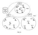
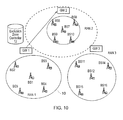
- Figure 4 illustrates a spectrum sharing scenario which includes first, second and third wireless communication systems, which in this case are radio access networks RAN1-3, and external circuitry, which in this case is an exclusion zone controller 12.
- the radio access networks RAN1-3 are operable in use to take part in a spectrum assignment process.
- the first radio access network RAN1 consists of first to fifth network elements, which in this case are base stations BS1-5, and a gateway GW1.
- the first radio access network RAN1 defines an exclusion zone 10 surrounding itself.
- the second radio access network RAN2 consists of sixth to tenth base stations BS6-10 and a gateway GW2.
- the third radio access network RAN3 consists of eleventh to sixteenth base stations BS11-16 and a gateway GW3.
- the exclusion zone controller 12 is located within communication range of the networks RAN1-3 and operates to determine the size of the exclusion zone 10, interacting with the networks RAN1-3 in a manner that will be described.
- the exclusion zone 10 indicates to any mobile communications apparatus located within the exclusion zone 10, for example user equipment, that is not permitted to communicate with either the second radio access network RAN2 or the third radio access network RAN3 using a portion of spectrum which was pre-assigned to the first radio access network RAN1 and which is currently, as part of the spectrum assignment process, re-assigned to either the second radio access network RAN2 or the third radio access network RAN3.
- the first radio access network RAN1 defines the exclusion zone 10 by transmitting a beacon signal from its gateway GW1.
- the strength of the beacon signal indicates the size of the exclusion zone 10.
- User equipment located within range of the gateway GW1 periodically listens to the beacon signal. If the beacon signal strength is above a specified threshold for that user equipment, the user equipment determines that it is within the exclusion zone 10 and stops any spectrum sharing or operation in the spectrum assigned to the gateway GW1.
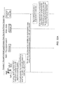
- the exclusion zone controller 12 is configured to send periodic requests to the first radio access network RAN1. In step S1 of Figure 16 , the exclusion zone controller 12 sends such a request.
- the gateway GW1 estimates the current maximum acceptable level of interference ⁇ inflicted on the base stations BS1-5 of the first radio access network RAN1 (i.e. interference on their corresponding cells).
- the maximum acceptable level of interference ⁇ is the sum of the safe interference levels that may be experienced by each cell and is recorded before operation of the first radio access network RAN1 as a result of a measurement campaign.
- each cell i.e. the cell of the respective base station BS1-5) sends its current maximum acceptable level of interference ⁇ n to the gateway GW1.
- the gateway GW1 then adds all the received values to determine the estimated ⁇ value.
- step S3 the gateway GW1 asks its assigned base stations BS1-5 to measure their own real interference measurements and reports of the total interference inflicted on their respective cells (or an indication of total interference in each cell) to the gateway GW1.
- step S4 the base stations BS1-5 provide this information to the gateway GW1.
- step S5 the gateway GW1 computes the difference between the maximum acceptable level of interference (as determined in step S2) and the sum of all the interferences measured and reported by the base stations BS1-5 (in step S3).
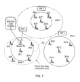
- the gateway GW1 signals this difference to the exclusion zone controller 12, as shown in Figure 5 .
- step S6 the exclusion zone controller 12 determines a desired size of the exclusion zone 10 in dependence on the difference as determined in step S5.
- the exclusion zone controller 12 stores a predefined mapping table of the difference (which is representative of the level of interference inflicted on the first radio access network RAN1) against the desired size of the exclusion zone 10, and uses the mapping table to look up a desired size of the exclusion zone 10 in accordance with the difference.
- the desired size of the exclusion zone 10 is represented by a desired power of the beacon signal, and it is the power of the beacon signal which is stored in the mapping table.
- the power of the beacon signal is proportional to the desired size of the exclusion zone 10 (the larger the desired size of the exclusion zone 10, the higher the power of the beacon signal).
- the exclusion zone controller 12 signals the desired power of the beacon signal to the gateway GW1 (see Figure 6 ) and, thus, the gateway GW1 is able to adjust the power of the beacon signal in order to vary the size of the exclusion zone 10 (i.e. such that the actual beacon signal power matches the desired beacon signal power).
- the exclusion zone controller 12 extends the exclusion zone 10 accordingly, as shown in Figure 6 . If the difference is high (i.e. the level of interference is low), in step S8, the exclusion zone controller 12 may shrink the exclusion zone 10, as shown in Figure 7 .
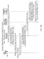
- Figure 14A illustrates the signalling which takes in the first arrangement.
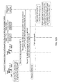
- a secondary system the second radio access network RAN2 requests a change in the size of the exclusion zone 10.
- Two or more other radio access networks RAN2 and RAN3 are sharing spectrum with the first radio access network RAN1. Due to higher traffic load, RAN2 is in urgent need for spectrum resources, and the need is detected and a request sent to the exclusion zone controller 12 in step S1. To have a better access to the spectrum which was pre-assigned to the first radio access network RAN1 and re-assigned to the second radio access network RAN2 in the spectrum assignment process, it needs to have the exclusion zone 10 reduced.
- step S2 the exclusion zone controller 12 asks the gateway GW2 assigned to the second radio access network RAN2 to provide an estimation of the interference it thinks it is inflicting on the first radio access network RAN1.
- step S3 the gateway GW2 estimates the current total level of interference inflicted on the cells of the first radio access network RAN1 based on its current transmission power level and link gains.
- step S4 the gateway GW2 asks the gateway GW1 to confirm the estimation, as shown in Figure 9 .
- step S5 the gateway GW1 confirms the estimated level of interference coming from the direction of the second radio access network RAN2 by signalling to the gateway GW2, as shown in Figure 10 . If the gateway GW1 does not confirm the estimation, the process will be stopped and the exclusion zone controller may decline the request for change.
- step S6 the gateway GW2 sends the confirmed value to the exclusion zone controller 12, as shown in Figure 11 .
- the exclusion zone controller 12 already has the knowledge of the maximum acceptable level of interference ⁇ which can be inflicted on the first radio access network RAN1 and determines the difference between the maximum acceptable level of interference ⁇ and the reported value from the gateway GW2.
- step S7 the exclusion zone controller 12 uses a predefined mapping table of the difference as determined in step S6 versus the size (e.g. area) of the exclusion zone 10 (i.e. the transmission power of the beacon signal) to determine the desired size of the exclusion zone 10.
- the exclusion zone controller 12 signals the desired power of the beacon signal to the gateway GW1 and, thus, the gateway GW1 is able to adjust the power of the beacon signal such that the actual beacon signal power matches the desired beacon signal power.
- step S8 the exclusion zone controller 12 extends the exclusion zone 10, as shown in Figure 12 , by increasing the beacon signal transmission power.
- step S9 if the difference is high, the exclusion zone controller 12 may shrink the exclusion zone 10, as shown in Figure 13 , by reducing the beacon signal transmission power.
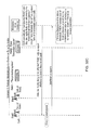
- Figure 14B illustrates the signalling which takes place in the second arrangement.
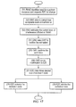
- step S1 of Figure 18 the exclusion zone controller 12 triggers a LT Spectrum Assignment, as shown in Figure 15 .
- Figure 14C illustrates the signalling which takes in the third arrangement.
- transceivers are fixed or they can move. They are distributed uniformly in a square region of dimension L ⁇ L . It is assumed that transceivers have the capability to listen to sub-channels and measure the interference received from other transceivers on each radio sub-band. It is assumed that the radio sub-channels are shared between the transceivers and that, if two transceivers choose the same radio sub-channel, it will have some impact on both depending on the radio channel between them. It is assumed that N transceivers form a cluster of transceivers. It is assumed that overall available spectrum has been divided into P sub channels and each transceiver might transmit at each time in M sub-channels so that M ⁇ P.
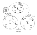
- Figures 19 to 36 relate to arrangements in which variations are made to the local size of an exclusion zone.
- a local beacon signal transmitter is assigned to each base station which has the potential to become involved in spectrum negotiations (in this case, local beacon signal transmitters LB3 and LB4 are assigned to base stations BS3 and BS4).
- Each local beacon signal is updated every time an update of the size of the exclusion zone 10 is necessary.
- the interference experienced by each base station BS3, BS4 is linked to the power strength of the beacon signal: the larger the level of interference, the larger the local size of the exclusion zone 10 and the stronger the beacon signal power.
- Any mobile communications apparatus in approach to the exclusion zone 10 periodically listens to the beacon signal. If the strength of the beacon signal is above a specified threshold for that mobile communications apparatus, the mobile communications apparatus determines that it is within the exclusion zone 10 and stops any spectrum sharing or operation in the spectrum assigned to the gateway GW1.
- a base station in the first radio access network RAN1 sends a request for a local variation in the size of the exclusion zone 10.
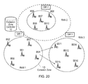
- step S1 base station BS4 in the first radio access network RAN1 gets involved in short term spectrum assignment negotiations with base stations BS11 and BS15 of the third radio access network RAN3, as shown in Figure 20 .
- step S2 after completing the short term assignment process, the base station BS4 realises that the interference level that the base stations BS1 and BS5 receive as a result of Short Term Spectrum Assignment is not significant. (As the base station BS2 is located far away from the negotiation area and from the base station BS4, it is unlikely that it will be affected by the interference coming from the third radio access network RAN3. In order to avoid unnecessary signalling, base stations that are located far away from the negotiation area or the negotiating base station may be ignored.)
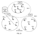
- step S3 the base station BS4 signals its interest for a smaller local size for exclusion zone directly to the exclusion zone controller 12, as shown in Figure 21 , in order to get even better and more short term assignment deals in future from the third radio access network RAN3.
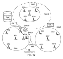
- step S4 the exclusion zone controller 12 maps the interference level to the size of a local variation in the exclusion zone 10 and, if it is less than the current local size, in step S5, it shrinks the exclusion zone 10 (for example by reducing the transmission power of the local beacon signal), as shown in Figure 22 . Otherwise, it increases the size of the local variation in step S6.
- a base station in the third radio access network RAN3 sends a request for a local variation in the size of the exclusion zone 10.
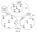
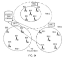
- Step S1 in this example, the base station BS4 from the first radio access network RAN1 gets involved in short term spectrum assignment negotiations with the base stations BS11 and BS15 of the third radio access network RAN3, as shown in Figure 23 .
- step S2 after completing the ST Spectrum Assignment process, the base stations BS11 and BS15 experience low SIR.
- step S3 the base stations BS11 and BS15 express their unhappiness with the SIR level by sending a request for a local reduction in the size of the exclusion zone 10 to the exclusion zone controller 12, as shown in Figure 24 .
- a local reduction in the size of the exclusion zone 10 would the base stations BS11 and BS15 to transmit with higher power and get potentially better short term spectrum assignment deals. (Any mobile communications apparatus in the area can perform more spectrum sharing closer to the centre of the first radio access network RAN1.)
- step S4 the exclusion zone controller 12 asks for the interference level from the base stations that are most likely to be affected by this specific spectrum assignment process (in this case, for example, the base stations BS1 and BS5).
- the exclusion zone controller 12 maps the current interference level to a local exclusion zone size. If the said size is below the current local size, in step S5, it shrinks the exclusion zone locally, as shown in Figure 25 (i.e. by reducing the transmission power of the local beacon signal). Otherwise, in step S6, the exclusion zone controller 12 increases the size of the exclusion zone locally.
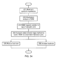
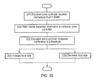
- step S1 the exclusion zone controller 12 periodically monitors the situation with the base stations that are most likely to be affected by the ongoing short term spectrum assignment negotiations. For example, in Figure 26 , the base stations BS1 and BS5 are most highly likely to be affected by the result of negotiations between the base station BS4 and the base stations BS15 or BS11. The exclusion zone controller 12 asks for the interference that the base stations BS1 and BS5 are currently experiencing in the band shared with the third radio access network RAN3, as shown in Figure 26 .
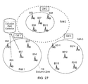
- step S2 the base stations BS1 and BS5 send back the requested information to the exclusion zone controller 12, as shown in Figure 27 .
- step S3 the exclusion zone controller 12 compares the interference to a threshold.
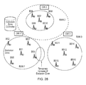
- step S4 the exclusion zone controller 12 may increase the local exclusion zone size, if the interference is above a threshold, as shown in Figure 28 . Otherwise, in step S5, it decreases the local size of the exclusion zone 10.
- the exclusion zone controller 12 may signal the latest updated local size of the exclusion zone 10 to the gateways GW1-3 and to all the higher layer network entities involved, including the entity in charge if spectrum co-existence and sharing.
- the exclusion zone controller 12 may still be made aware of the decision made locally. Avoiding reliance on the decision made by the exclusion zone controller 12 has the disadvantage of not being aware of what is going on with regard to RAN-wide with other local negotiations and local changes of exclusion zones, as the exclusion zone controller 12 has the information on this.
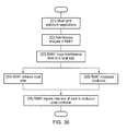
- step S1 the base station BS4 gets involved in short term spectrum assignment negotiations with base stations BS11 and BS15 of the third radio access network RAN3, as shown in Figure 29 .
- step S2 after completing the Short Term Spectrum Assignment process, the base station BS4 of the first radio access network RAN1 realises that the interference level that the base stations BS1 and BS5 receive as a result of Short Term Spectrum Assignment is not significant.
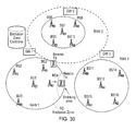
- step S3 the base station BS4 maps the interference level to a local size of the exclusion zone 10. If the said local size is less than the current local size, in step 4, the base station BS4 shrinks the exclusion zone 10, for example by reducing the transmission power of the local beacon signal, as shown in Figure 30 , by signalling the new beacon power level to its local beacon transmitter LB4. Otherwise, in step S5, the base station BS4 increases the local size of the exclusion zone.
- step S6 the base station BS4 then signals the new local size of the exclusion zone 10 to the exclusion zone controller 12, as shown in Figure 31 . This is to let the exclusion zone controller 12 have an accurate idea about the current size and formation of the exclusion zone 10. Otherwise this is going to be problematic when a slow exclusion zone change is performed in line with LT Spectrum Assignment.
- FIG 37 illustrates a spectrum sharing scenario which involves three wireless sensor networks (RFID networks): wireless sensor network 1, wireless sensor network 2 and wireless sensor network 3.
- Each wireless sensor network includes a number of sinks (wireless sensor node base stations), e.g. the sinks 1-5 shown in each network in Figure 37 , and each wireless sensor network is in communication with a number of wireless sensors (RFID sensors/tags), e.g. the RFID or wireless sensors 1-5 shown in each network in Figure 37 .
- An exclusion shown 10 is shown surrounding the first wireless sensor network 1. The size of the exclusion zone 10 may be adjusted in any of the ways described herein, and the above disclosure applied equally to situation including wireless sensor networks as shown in Figure 37 .
- circuitry may have other functions in addition to the mentioned functions, and that these functions may be performed by the same circuit.
Landscapes
- Engineering & Computer Science (AREA)
- Computer Networks & Wireless Communication (AREA)
- Signal Processing (AREA)
- Mobile Radio Communication Systems (AREA)
Applications Claiming Priority (1)
| Application Number | Priority Date | Filing Date | Title |
|---|---|---|---|
| GB0725051A GB0725051D0 (en) | 2007-12-21 | 2007-12-21 | Communications system |
Publications (1)
| Publication Number | Publication Date |
|---|---|
| EP2073584A1 true EP2073584A1 (fr) | 2009-06-24 |
Family
ID=39048612
Family Applications (1)
| Application Number | Title | Priority Date | Filing Date |
|---|---|---|---|
| EP20080171673 Withdrawn EP2073584A1 (fr) | 2007-12-21 | 2008-12-15 | Systèmes de communication |
Country Status (4)
| Country | Link |
|---|---|
| US (1) | US20090163215A1 (fr) |
| EP (1) | EP2073584A1 (fr) |
| JP (1) | JP5233653B2 (fr) |
| GB (1) | GB0725051D0 (fr) |
Cited By (2)
| Publication number | Priority date | Publication date | Assignee | Title |
|---|---|---|---|---|
| WO2015197537A1 (fr) * | 2014-06-23 | 2015-12-30 | Telefonaktiebolaget L M Ericsson (Publ) | Technique pour le partage de fréquences |
| EP3952384A4 (fr) * | 2019-03-29 | 2022-04-20 | Sony Group Corporation | Dispositif de commande de communication, dispositif de communication et procédé de commande de communication |
Families Citing this family (7)
| Publication number | Priority date | Publication date | Assignee | Title |
|---|---|---|---|---|
| FI20075859A0 (fi) * | 2007-11-30 | 2007-11-30 | Nokia Corp | Järjestelmien välinen häiriökontrolli |
| US8521636B2 (en) * | 2008-12-04 | 2013-08-27 | Spectrum Bridge, Inc. | Automated spectrum exchange system and method |
| US8725192B2 (en) * | 2009-07-24 | 2014-05-13 | Qualcomm Incorporated | Beacon transmit power schemes |
| US20140029529A1 (en) * | 2012-07-25 | 2014-01-30 | Qualcomm Incorporated | Asymmetric radio access network (ran) resource allocation in ran sharing arrangement |
| US10536858B2 (en) * | 2015-06-03 | 2020-01-14 | The Aerospace Corporation | Spectrum sharing based on signal-based shared access |
| EP3393163B1 (fr) * | 2016-01-11 | 2022-08-31 | Huawei Technologies Co., Ltd. | Procédés et appareil de communication sans fil |
| WO2025212788A1 (fr) * | 2024-04-05 | 2025-10-09 | Hughes Network Systems, Llc | Gestion d'interférence de co-canal leo basée sur un séjour dans un espace uv |
Citations (5)
| Publication number | Priority date | Publication date | Assignee | Title |
|---|---|---|---|---|
| US5412658A (en) | 1993-10-22 | 1995-05-02 | Bell Communications Research, Inc. | Beacon detection method and apparatus for sharing spectrum between wireless communications systems and fixed microwave systems |
| WO1995027381A1 (fr) | 1994-04-05 | 1995-10-12 | Celsat America, Inc. | Systeme et procede de communications mobiles coexistants avec des systemes de communications deja en place |
| US5497503A (en) * | 1993-05-28 | 1996-03-05 | Ameritech Corporation | Method for assigning frequency channels in a cellular communication system and for identifying critical existing fixed microwave receivers that restrict operation of such a system |
| WO2007122297A1 (fr) * | 2006-04-26 | 2007-11-01 | Nokia Corporation | Utilisation du spectre dans un systeme radio |
| WO2008035287A2 (fr) * | 2006-09-18 | 2008-03-27 | Nokia Corporation | Procédé et appareil pour la diminution de la bande de garde entre des systèmes de communication sans fil fonctionnant dans la même région géographique |
Family Cites Families (40)
| Publication number | Priority date | Publication date | Assignee | Title |
|---|---|---|---|---|
| JP3014149B2 (ja) * | 1991-02-28 | 2000-02-28 | 株式会社日立製作所 | 移動通信システムにおける干渉低減方法 |
| US5428815A (en) * | 1991-04-30 | 1995-06-27 | Motorola,Inc. | Communication system with geographic reuse dynamically sensitive to communication unit type |
| US5790587A (en) * | 1991-05-13 | 1998-08-04 | Omnipoint Corporation | Multi-band, multi-mode spread-spectrum communication system |
| GB2290195B (en) * | 1994-06-10 | 1998-08-05 | Northern Telecom Ltd | Automatic determination and tuning of pico-cell topology for low-power wireless systems |
| US6473623B1 (en) * | 1996-04-18 | 2002-10-29 | At&T Wireless Services, Inc. | Method for self-calibration of a wireless communication system |
| FI109514B (fi) * | 1997-04-25 | 2002-08-15 | Nokia Corp | Menetelmä kanavien allokoimiseksi |
| FI973837A7 (fi) * | 1997-09-29 | 1999-03-30 | Nokia Telecommunications Oy | Tiedonsiirtoresurssien allokointi |
| US7054635B1 (en) * | 1998-11-09 | 2006-05-30 | Telefonaktiebolaget Lm Ericsson (Publ) | Cellular communications network and method for dynamically changing the size of a cell due to speech quality |
| US6434390B2 (en) * | 1999-06-03 | 2002-08-13 | Lucent Technologies Inc. | Macrodiversity control system having macrodiversity mode based on operating category of wireless unit |
| US7146176B2 (en) * | 2000-06-13 | 2006-12-05 | Shared Spectrum Company | System and method for reuse of communications spectrum for fixed and mobile applications with efficient method to mitigate interference |
| US7995989B2 (en) * | 2000-12-29 | 2011-08-09 | Globalstar, Inc. | Method and apparatus providing suppression of system access by use of confidence polygons, volumes and surfaces in a mobile satellite system |
| US6795716B2 (en) * | 2001-05-14 | 2004-09-21 | Lucent Technologies Inc. | System and method of operating a wireless base station with quantized use of transmitter power |
| US7603117B2 (en) * | 2001-09-14 | 2009-10-13 | Atc Technologies, Llc | Systems and methods for terrestrial use of cellular satellite frequency spectrum |
| US7623859B2 (en) * | 2001-09-14 | 2009-11-24 | Atc Technologies, Llc | Additional aggregate radiated power control for multi-band/multi-mode satellite radiotelephone communications systems and methods |
| US7062267B2 (en) * | 2001-09-14 | 2006-06-13 | Atc Technologies, Llc | Methods and systems for modifying satellite antenna cell patterns in response to terrestrial reuse of satellite frequencies |
| JP2003143015A (ja) * | 2001-11-07 | 2003-05-16 | Sony Corp | 信号処理方法及び装置並びに符号列生成方法及び装置 |
| EP1479256B1 (fr) * | 2002-02-25 | 2006-11-29 | Telefonaktiebolaget LM Ericsson (publ) | Reattribution dynamique d'un spectre de frequence |
| US7046655B2 (en) * | 2002-08-15 | 2006-05-16 | Interdigital Technology Corporation | Wireless communication method and system for minimizing interference by determining mobile station zone locations and potential conflicts between cell zones |
| WO2004038549A2 (fr) * | 2002-10-24 | 2004-05-06 | Bbnt Solutions Llc | Mise en reseau adaptative du point de vue du spectre |
| CN1567869B (zh) * | 2003-06-30 | 2010-05-05 | 叶启祥 | 可避免干扰损坏并增加空间再用率的干扰控制方法 |
| US7573856B2 (en) * | 2003-11-25 | 2009-08-11 | Telefonaktiebolaget Lm Ericsson (Publ) | Power-based rate adaptation of wireless communication channels |
| US7853292B2 (en) * | 2004-05-06 | 2010-12-14 | Alcatel-Lucent Usa Inc. | Distributed resource management for enhanced dedicated channel |
| US7783259B2 (en) * | 2004-09-28 | 2010-08-24 | Microtune (Texas), L.P. | System and method of eliminating or minimizing LO-related interference from tuners |
| US9161231B2 (en) * | 2004-10-14 | 2015-10-13 | Alcatel Lucent | Method and system for wireless networking using coordinated dynamic spectrum access |
| US7519385B2 (en) * | 2004-10-29 | 2009-04-14 | Hien Nguyen | Wireless access point (AP) automatic channel selection and automatic power adjustment |
| US7415288B1 (en) * | 2005-01-07 | 2008-08-19 | Zte (Usa) Inc. | Techniques for providing efficient transmit diversity and bandwidth segmentation in a wireless communication system |
| KR20060097450A (ko) * | 2005-03-09 | 2006-09-14 | 삼성전자주식회사 | 다중 셀 통신 시스템에서 자원 할당 제어 시스템 및 방법 |
| JP4636241B2 (ja) * | 2005-03-31 | 2011-02-23 | 日本電気株式会社 | 通信規制システムおよび通信規制方法 |
| KR100943614B1 (ko) * | 2005-05-31 | 2010-02-24 | 삼성전자주식회사 | 다중 무선 접속 네트워크 환경에서 주파수 자원 관리시스템 및 그 방법 |
| US20070010237A1 (en) * | 2005-07-05 | 2007-01-11 | Airgo Networks, Inc. | Mac-level protection for networking extended-range and legacy devices in a wireless network |
| JP4668270B2 (ja) * | 2005-07-08 | 2011-04-13 | シャープ株式会社 | 通信装置、通信方法、通信プログラムおよびその記録媒体 |
| US7711028B2 (en) * | 2005-08-02 | 2010-05-04 | The Mitre Corporation | Spectrum shaping using code-hopping CDMA |
| KR101027480B1 (ko) * | 2006-01-04 | 2011-04-06 | 삼성전자주식회사 | 통신 시스템에서 데이터 송수신 방법 및 시스템 |
| EP1838116A1 (fr) * | 2006-03-22 | 2007-09-26 | Matsushita Electric Industrial Co., Ltd. | Gestion d'interférences entre cellules radio voisines dans un système de SC-FDMA |
| US9374714B2 (en) * | 2006-03-22 | 2016-06-21 | Alcatel Lucent | Methods of configuring cells in a network using neighborhoods and method of dynamically configuring cells in a network using neighborhoods |
| US8520606B2 (en) * | 2006-10-23 | 2013-08-27 | Samsung Electronics Co., Ltd | Synchronous spectrum sharing based on OFDM/OFDMA signaling |
| US8483038B2 (en) * | 2006-12-04 | 2013-07-09 | Ntt Docomo, Inc. | Radio communication apparatus and radio communication method |
| WO2008073007A1 (fr) * | 2006-12-11 | 2008-06-19 | Telefonaktiebolaget Lm Ericsson (Publ) | Procédé et dispositif pour générer une couverture dans un réseau cellulaire |
| US8064475B2 (en) * | 2007-03-21 | 2011-11-22 | At&T Intellectual Property I, L.P. | Systems and methods of wireless communication |
| US7813739B2 (en) * | 2007-09-27 | 2010-10-12 | Koon Hoo Teo | Method for reducing inter-cell interference in wireless OFDMA networks |
-
2007
- 2007-12-21 GB GB0725051A patent/GB0725051D0/en not_active Ceased
-
2008
- 2008-12-15 EP EP20080171673 patent/EP2073584A1/fr not_active Withdrawn
- 2008-12-15 US US12/335,515 patent/US20090163215A1/en not_active Abandoned
- 2008-12-19 JP JP2008323594A patent/JP5233653B2/ja not_active Expired - Fee Related
Patent Citations (5)
| Publication number | Priority date | Publication date | Assignee | Title |
|---|---|---|---|---|
| US5497503A (en) * | 1993-05-28 | 1996-03-05 | Ameritech Corporation | Method for assigning frequency channels in a cellular communication system and for identifying critical existing fixed microwave receivers that restrict operation of such a system |
| US5412658A (en) | 1993-10-22 | 1995-05-02 | Bell Communications Research, Inc. | Beacon detection method and apparatus for sharing spectrum between wireless communications systems and fixed microwave systems |
| WO1995027381A1 (fr) | 1994-04-05 | 1995-10-12 | Celsat America, Inc. | Systeme et procede de communications mobiles coexistants avec des systemes de communications deja en place |
| WO2007122297A1 (fr) * | 2006-04-26 | 2007-11-01 | Nokia Corporation | Utilisation du spectre dans un systeme radio |
| WO2008035287A2 (fr) * | 2006-09-18 | 2008-03-27 | Nokia Corporation | Procédé et appareil pour la diminution de la bande de garde entre des systèmes de communication sans fil fonctionnant dans la même région géographique |
Cited By (2)
| Publication number | Priority date | Publication date | Assignee | Title |
|---|---|---|---|---|
| WO2015197537A1 (fr) * | 2014-06-23 | 2015-12-30 | Telefonaktiebolaget L M Ericsson (Publ) | Technique pour le partage de fréquences |
| EP3952384A4 (fr) * | 2019-03-29 | 2022-04-20 | Sony Group Corporation | Dispositif de commande de communication, dispositif de communication et procédé de commande de communication |
Also Published As
| Publication number | Publication date |
|---|---|
| US20090163215A1 (en) | 2009-06-25 |
| GB0725051D0 (en) | 2008-01-30 |
| JP2009171568A (ja) | 2009-07-30 |
| JP5233653B2 (ja) | 2013-07-10 |
Similar Documents
| Publication | Publication Date | Title |
|---|---|---|
| EP2073584A1 (fr) | Systèmes de communication | |
| EP2073585B1 (fr) | Systèmes de communication | |
| US9313750B2 (en) | Frequency management apparatus and frequency management method in wireless system | |
| CN102624465B (zh) | 一种认知无线电的感知辅助的方法及系统 | |
| EP2612527B1 (fr) | Procédé et configuration permettant une allocation d'espace blanc | |
| EP2215753B1 (fr) | Contrôle d'interférences entre systèmes | |
| EP2770789B1 (fr) | Hiérarchisation prédictive et contextuelle d'un accès au spectre | |
| EP2083592B1 (fr) | Procédé et appareil pour contrôler l'utilisation du spectre dans un système de communications sans fils | |
| EP3664495B1 (fr) | Dispositif de commande, dispositif sans fil, procédé et support d'enregistrement | |
| EP2083591A1 (fr) | Systèmes de communication avec allocation de spectre basée sur des conditions de réseau | |
| JP5136443B2 (ja) | 通信システム | |
| EP2679055B1 (fr) | Procédé et système pour réguler le brouillage agrégé dans des réseaux radio cognitifs | |
| EP2073586A2 (fr) | Attribution de spectre dans des systèmes de communications sans fil | |
| JPWO2019230671A1 (ja) | 無線装置、端末、方法およびコンピュータプログラム | |
| WO2017009272A1 (fr) | Procédés et appareils permettant de déterminer une cellule équivalente dans un réseau de communication | |
| EP3161518B1 (fr) | Procédé et appareil de protection contre les interférences | |
| EP3148238B1 (fr) | Procédé et appareil de régulation du brouillage, et dispositif élément de réseau | |
| CN105393573B (zh) | 一种干扰控制方法、装置及网元设备 | |
| KR20110070761A (ko) | 인지 무선 시스템에서의 전송 전력 할당방법 | |
| US20230328533A1 (en) | Methods and apparatus for low complexity spectrum sharing | |
| KR101093220B1 (ko) | 셀의 경계 영역에 설치되는 셀간 간섭 조정장치 및 셀의 경계 영역에 위치하는 이동단말에 대한 셀간 간섭 조정방법 | |
| KR20110078298A (ko) | 캐리어 주파수 대역 또는 세그먼트를 할당 변경하는 방법 및 펨토형 기지국의 송신 전력을 관리하는 방법 |
Legal Events
| Date | Code | Title | Description |
|---|---|---|---|
| PUAI | Public reference made under article 153(3) epc to a published international application that has entered the european phase |
Free format text: ORIGINAL CODE: 0009012 |
|
| AK | Designated contracting states |
Kind code of ref document: A1 Designated state(s): AT BE BG CH CY CZ DE DK EE ES FI FR GB GR HR HU IE IS IT LI LT LU LV MC MT NL NO PL PT RO SE SI SK TR |
|
| AX | Request for extension of the european patent |
Extension state: AL BA MK RS |
|
| 17P | Request for examination filed |
Effective date: 20091221 |
|
| AKX | Designation fees paid |
Designated state(s): DE FR GB |
|
| 17Q | First examination report despatched |
Effective date: 20120504 |
|
| GRAP | Despatch of communication of intention to grant a patent |
Free format text: ORIGINAL CODE: EPIDOSNIGR1 |
|
| INTG | Intention to grant announced |
Effective date: 20150421 |
|
| RIN1 | Information on inventor provided before grant (corrected) |
Inventor name: ABEDI, SAIED |
|
| STAA | Information on the status of an ep patent application or granted ep patent |
Free format text: STATUS: THE APPLICATION IS DEEMED TO BE WITHDRAWN |
|
| 18D | Application deemed to be withdrawn |
Effective date: 20150902 |