EP2073602A2 - Dispositif de chauffage doté d'un moyen de protection multifonction - Google Patents
Dispositif de chauffage doté d'un moyen de protection multifonction Download PDFInfo
- Publication number
- EP2073602A2 EP2073602A2 EP08021639A EP08021639A EP2073602A2 EP 2073602 A2 EP2073602 A2 EP 2073602A2 EP 08021639 A EP08021639 A EP 08021639A EP 08021639 A EP08021639 A EP 08021639A EP 2073602 A2 EP2073602 A2 EP 2073602A2
- Authority
- EP
- European Patent Office
- Prior art keywords
- heating
- heating device
- heating element
- filling
- jacket
- Prior art date
- Legal status (The legal status is an assumption and is not a legal conclusion. Google has not performed a legal analysis and makes no representation as to the accuracy of the status listed.)
- Ceased
Links
Images
Classifications
-
- H—ELECTRICITY
- H05—ELECTRIC TECHNIQUES NOT OTHERWISE PROVIDED FOR
- H05B—ELECTRIC HEATING; ELECTRIC LIGHT SOURCES NOT OTHERWISE PROVIDED FOR; CIRCUIT ARRANGEMENTS FOR ELECTRIC LIGHT SOURCES, IN GENERAL
- H05B3/00—Ohmic-resistance heating
- H05B3/78—Heating arrangements specially adapted for immersion heating
-
- F—MECHANICAL ENGINEERING; LIGHTING; HEATING; WEAPONS; BLASTING
- F24—HEATING; RANGES; VENTILATING
- F24H—FLUID HEATERS, e.g. WATER OR AIR HEATERS, HAVING HEAT-GENERATING MEANS, e.g. HEAT PUMPS, IN GENERAL
- F24H1/00—Water heaters, e.g. boilers, continuous-flow heaters or water-storage heaters
- F24H1/10—Continuous-flow heaters, i.e. heaters in which heat is generated only while the water is flowing, e.g. with direct contact of the water with the heating medium
- F24H1/101—Continuous-flow heaters, i.e. heaters in which heat is generated only while the water is flowing, e.g. with direct contact of the water with the heating medium using electric energy supply
- F24H1/102—Continuous-flow heaters, i.e. heaters in which heat is generated only while the water is flowing, e.g. with direct contact of the water with the heating medium using electric energy supply with resistance
- F24H1/103—Continuous-flow heaters, i.e. heaters in which heat is generated only while the water is flowing, e.g. with direct contact of the water with the heating medium using electric energy supply with resistance with bare resistances in direct contact with the fluid
-
- F—MECHANICAL ENGINEERING; LIGHTING; HEATING; WEAPONS; BLASTING
- F24—HEATING; RANGES; VENTILATING
- F24H—FLUID HEATERS, e.g. WATER OR AIR HEATERS, HAVING HEAT-GENERATING MEANS, e.g. HEAT PUMPS, IN GENERAL
- F24H1/00—Water heaters, e.g. boilers, continuous-flow heaters or water-storage heaters
- F24H1/10—Continuous-flow heaters, i.e. heaters in which heat is generated only while the water is flowing, e.g. with direct contact of the water with the heating medium
- F24H1/12—Continuous-flow heaters, i.e. heaters in which heat is generated only while the water is flowing, e.g. with direct contact of the water with the heating medium in which the water is kept separate from the heating medium
- F24H1/14—Continuous-flow heaters, i.e. heaters in which heat is generated only while the water is flowing, e.g. with direct contact of the water with the heating medium in which the water is kept separate from the heating medium by tubes, e.g. bent in serpentine form
- F24H1/142—Continuous-flow heaters, i.e. heaters in which heat is generated only while the water is flowing, e.g. with direct contact of the water with the heating medium in which the water is kept separate from the heating medium by tubes, e.g. bent in serpentine form using electric energy supply
-
- F—MECHANICAL ENGINEERING; LIGHTING; HEATING; WEAPONS; BLASTING
- F24—HEATING; RANGES; VENTILATING
- F24H—FLUID HEATERS, e.g. WATER OR AIR HEATERS, HAVING HEAT-GENERATING MEANS, e.g. HEAT PUMPS, IN GENERAL
- F24H1/00—Water heaters, e.g. boilers, continuous-flow heaters or water-storage heaters
- F24H1/18—Water-storage heaters
- F24H1/20—Water-storage heaters with immersed heating elements, e.g. electric elements or furnace tubes
- F24H1/201—Water-storage heaters with immersed heating elements, e.g. electric elements or furnace tubes using electric energy supply
- F24H1/202—Water-storage heaters with immersed heating elements, e.g. electric elements or furnace tubes using electric energy supply with resistances
Definitions
- the invention relates to a heating device for heating liquid media, in particular a submersible heating device for heating drinking water and / or process water in domestic hot water tanks, dishwashers or washing machines, according to the preamble of claim 1.
- immersible heaters are known, for example, for DHW heating, such as immersion heaters or electric heating cartridges.
- Such heaters have a heating element comprising a thin current-carrying heating or resistance wire and an enveloping, for example metallic tube.
- the heating wire is galvanically separated from the metal tube by an insulating layer surrounding it.
- the metal tube may be bent in the form of a helix.
- heating wire, insulating layer and metal tube form a structural unit and are not mutually movable.
- the heat transfer from the heating element to the surrounding medium is adversely affected, which can then lead to overheating of the heating element and in consequence to a bursting of the metal tube.
- the insulating function of the insulating layer is impaired and, due to penetration of the surrounding liquid medium into the heating element, corrosion and finally failure of the heating device occur.
- the US 2002/0090209 A1 discloses a flexible spiral heating element whose flexibility dictates its temperature-dependent expansion and contraction, thereby breaking and blasting off deposits on the heating element. The effect is made possible by the shape of the heating element.
- the heating element is covered by a thin polymer layer.
- the DE 94 21 924 U1 shows an electric heating resistor with two-layer support, which is formed by a metal layer and an outer layer of gold. As a result, the adhesion of deposits on the heating resistor is much weaker than with the classic resistors.
- the invention has for its object to provide a heater which has an optimized protection. In addition, it is an object of the present invention to provide a heating device which has a longer life. In addition, it is an object of the present invention to provide a heating device which has an effective and optimized heat transfer to the environment.
- the heating device for heating liquid media in particular a submergible heating device for drinking water and / or service water, comprising a heating element for generating and emitting heat energy to a surrounding liquid medium, is characterized in that the heating device further in relation to the heating element geometrically variable multifunctional protection for preventing at least deposits and corrosion on the heating element.
- the heating device in this case has a multi-functional protection means, which seals the heating element against the surrounding medium, such as drinking or service water and the like.
- the multi-functional protection agent is preferably a mechanical protection agent, which forms a purely mechanical protection for the heating element and does not include sacrificial electrodes, electrochemical or chemical agents.
- the multi-functional protection means is designed as a multi-function protection means that can be changed in relation to the heating element.
- the multi-functional protection means is formed in its geometric shape changeable relative to the heating element, that is, it can at least partially move relative to the heating element, auslusn, expand, rotate, change its shape, etc., so as to ensure optimum protection by the change ,
- the multi-functional protection means is designed as an expansion element enclosing the heating element in order to expand or contract according to an applied temperature.
- the expansion element has a jacket surrounding the heating element and a filling arranged between the heating element and the jacket into which the heating element is at least partially embedded.
- the filling comprises a material which is of the same design as the material of the surrounding jacket, so that the expansion element is formed as a solid material.
- the filling comprises a material selected from the group of materials which undergo a phase change when heated within producible temperature ranges by the heating element, comprising paraffins and the like.
- the filling comprises a material selected from the group of materials that do not undergo phase change when heated within producible temperature ranges by the heating element, including liquids and the like.
- the expander further comprises heat conductivity enhancers comprising graphite and the like to enhance heat transfer from the heater to the environment.
- the heat conductivity-increasing substances are integrated as particles in the filling and / or the jacket.
- the heating element is designed as an electric immersion heater with a power supply part and a heating filiform part protruding therefrom.
- the jacket approximately cylindrical surrounds the protruding part.
- the variable multifunctional protection agent effectively prevents deposits.
- the adhering deposits break when the multifunctional protection agent changes accordingly.
- the heat generated can be used in addition to the heating in addition to changing the multi-functional protection.
- the multifunctional protection agent expands, any deposits that may be present being released and / or removed by the expansion. If no heat is generated, the expansion element contracts again.
- lime deposits effectively burst from the surrounding or enveloping expansion element.
- the expansion element may have a simple geometry, which does not have to follow a shape of the heating element, but only envelops or embeds it.
- thermal conductivity By means of a corresponding filling, a corresponding thermal conductivity can be achieved with efficient heat transfer to the surrounding liquid medium.
- thermally conductive particles may be integrated into the filling in order to realize an improved thermal conductivity.
- the filling may comprise different materials, for example materials which undergo a phase change with a temperature change, for example from a solid state to a liquid state and vice versa.
- the heater can be implemented in any form, for example as a heating cartridge, immersion heaters and the like.
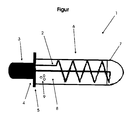
- the single FIGURE shows a heating device 1, which is designed in the form of an electric immersion heater.
- the heating device 1 comprises a heating element 2 for generating and emitting heat.
- the heating element 2 is formed as a coiled tube in the interior of which a current-carrying heating or resistance wire runs.
- the heating element 2 is connected at both ends to a power unit 3, which supplies and dissipates energy for heat generation.
- the power unit 3 may be formed as a battery, a power supply, or the like.
- a housing 4 is arranged to the power unit 3. This housing 4 surrounds the power unit 3 and has a shoulder 5, from which the heating element extends away from the power unit 3.
- the part of the heating element extending away from the energy unit 3 is surrounded by a multifunctional protection means 6, so that the part of the heating element 2 protruding from the energy unit 3 is not exposed to a surrounding liquid medium.
- the multifunctional protection means 6 is designed as a variable multifunctional protection means 6, that is, the multifunctional protection means 6 may vary in shape, length, diameter, strength and the like, in particular in relation to the other parts of the heating device 1, such as the heating element 2 or the stopper fifth move.
- the multifunctional protection means 6 is formed in the present figure as an expansion element and comprises a jacket 7, which surrounds the protruding part of the heating element and closes with the paragraph 5, so that the outstanding part of the heating element is completely surrounded by the jacket 7 and against the surrounding liquid Medium, such as water, drinking water or other liquids, is sealed. Further, the multi-functional protection means 6 designed as an expansion element comprises a filling 8, which is surrounded by the jacket 7 and the shoulder 5.
- the filling 8 comprises a material in which the heating element 2 is embedded, and which may correspond to the material of the jacket 7 or is designed differently.
- the material for the filling 8 may comprise a material which, when heat is generated by the heating element 2, changes its state of aggregation, that is, undergoes a phase change, such as from a solid state to a liquid state or vice versa.
- the filling 8 and / or the jacket 7 can have heat-conductivity-increasing substances 9, which are integrated, for example, in the filling 8 and / or in the jacket 7.
- These heat conductivity-increasing substances 9 may be, for example, graphite and serve to better deliver the heat energy provided to the heating element to the surrounding liquid medium.
- the jacket 7, which surrounds the filling 8, may have any shape, but is preferably substantially cylindrical, as an envelope, formed around the heating element.
Landscapes
- Resistance Heating (AREA)
- Heat-Pump Type And Storage Water Heaters (AREA)
Applications Claiming Priority (1)
| Application Number | Priority Date | Filing Date | Title |
|---|---|---|---|
| DE200710061837 DE102007061837B3 (de) | 2007-12-20 | 2007-12-20 | Heizvorrichtung mit Multifunktionsschutzmittel |
Publications (2)
| Publication Number | Publication Date |
|---|---|
| EP2073602A2 true EP2073602A2 (fr) | 2009-06-24 |
| EP2073602A3 EP2073602A3 (fr) | 2009-11-11 |
Family
ID=40157689
Family Applications (1)
| Application Number | Title | Priority Date | Filing Date |
|---|---|---|---|
| EP08021639A Ceased EP2073602A3 (fr) | 2007-12-20 | 2008-12-12 | Dispositif de chauffage doté d'un moyen de protection multifonction |
Country Status (2)
| Country | Link |
|---|---|
| EP (1) | EP2073602A3 (fr) |
| DE (1) | DE102007061837B3 (fr) |
Families Citing this family (4)
| Publication number | Priority date | Publication date | Assignee | Title |
|---|---|---|---|---|
| DE102012025098A1 (de) * | 2012-12-20 | 2014-06-26 | Rotorcomp Verdichter Gmbh | Heizungsanordnung |
| CN108050705A (zh) * | 2017-11-29 | 2018-05-18 | 贵州大学 | 一种防止结垢的加热装置 |
| CN108601122A (zh) * | 2018-07-04 | 2018-09-28 | 安徽永牧机械集团有限公司 | 一种浸没式加热器 |
| CN113108459A (zh) * | 2021-05-17 | 2021-07-13 | 界首市科漫电子科技有限公司 | 一种节能低垢即热热水器 |
Citations (2)
| Publication number | Priority date | Publication date | Assignee | Title |
|---|---|---|---|---|
| DE9421924U1 (de) | 1993-12-03 | 1997-05-07 | Seb S.A., Ecully | Elektrischer Heizwiderstand für einen Behälter für die Aufnahme von aufzuheizendem Wasser, insbesondere für einen Kessel |
| US20020090209A1 (en) | 2001-01-08 | 2002-07-11 | Watlow Polymer Technologies | Flexible spirally shaped heating element |
Family Cites Families (5)
| Publication number | Priority date | Publication date | Assignee | Title |
|---|---|---|---|---|
| FR2777410B1 (fr) * | 1998-04-09 | 2002-06-28 | Acova | Dispositif formant thermoplongeur pouvant etre utilise notamment dans un radiateur de chauffage a circulation d'eau |
| DE20004518U1 (de) * | 2000-03-10 | 2000-05-25 | Türk & Hillinger GmbH, 78532 Tuttlingen | Befestigung für Heizpatrone |
| FR2809276B1 (fr) * | 2000-05-17 | 2002-07-19 | Acova | Dispositif formant thermoplongeur pouvant etre utilise notamment dans un radiateur de chauffage a circulation d'eau |
| WO2002101303A1 (fr) * | 2001-06-08 | 2002-12-19 | Corona Lopez Romulo | Chauffe-eau equipe d'un dispositif thermoelectrique utilisant de l'huile de silicone |
| KR100479506B1 (ko) * | 2002-03-09 | 2005-03-31 | 김용옥 | 전기 히터장치 |
-
2007
- 2007-12-20 DE DE200710061837 patent/DE102007061837B3/de not_active Expired - Fee Related
-
2008
- 2008-12-12 EP EP08021639A patent/EP2073602A3/fr not_active Ceased
Patent Citations (2)
| Publication number | Priority date | Publication date | Assignee | Title |
|---|---|---|---|---|
| DE9421924U1 (de) | 1993-12-03 | 1997-05-07 | Seb S.A., Ecully | Elektrischer Heizwiderstand für einen Behälter für die Aufnahme von aufzuheizendem Wasser, insbesondere für einen Kessel |
| US20020090209A1 (en) | 2001-01-08 | 2002-07-11 | Watlow Polymer Technologies | Flexible spirally shaped heating element |
Also Published As
| Publication number | Publication date |
|---|---|
| EP2073602A3 (fr) | 2009-11-11 |
| DE102007061837B3 (de) | 2009-01-29 |
Similar Documents
| Publication | Publication Date | Title |
|---|---|---|
| DE102012107600B4 (de) | Elektrische Heizvorrichtung zum Beheizen von Fluiden | |
| DE102007061837B3 (de) | Heizvorrichtung mit Multifunktionsschutzmittel | |
| DE102015114886B4 (de) | Verfahren zur Herstellung einer Heizvorrichtung für Fluide | |
| EP1967712A3 (fr) | Corps en nid d'abeille pouvant être chauffé électriquement et son procédé de fonctionnement | |
| DE102009058159B4 (de) | Filtereinrichtung für Fluide mit einer elektrischen Heizung und Heizung für eine Filtereinrichtung | |
| EP1777452B1 (fr) | Connecteur chauffable | |
| KR100963052B1 (ko) | 코팅된 나선형 발열선을 이용한 전기 순간온수 발생기엘리먼트 | |
| EP2087224A1 (fr) | Dispositif de chauffage de carburant | |
| EP1529470B2 (fr) | Module de chauffage avec surface chauffante et chaudière instantanée et procédé pour sa fabrication | |
| EP2188575B1 (fr) | Appareil à eau chaude | |
| DE19846282B4 (de) | Elektrische Heizeinrichtung | |
| DE102008030541A1 (de) | Durchlauferhitzer zur Getränkebereitung | |
| DE102004060949A1 (de) | Dickschichtheizung für Fluide und Durchlauferhitzer | |
| DE102007027413B4 (de) | Reduktionsmittelversorgungssystem für einen Abgasreinigungskatalysator eines Verbrennungsmotors | |
| EP2471338B1 (fr) | Dispositif de connexion électrique d'un tuyau chauffé | |
| EP3424266B1 (fr) | Cartouche de chauffage avec un tube de protection | |
| DE202009011904U1 (de) | Heizelement | |
| EP1964496B1 (fr) | Chauffe-eau instantané | |
| DE10029244A1 (de) | Elektrische Heizvorrichtung | |
| DE202013101265U1 (de) | Medienleitung | |
| DE102019202045A1 (de) | Elektrische Heizvorrichtung | |
| DE19545155A1 (de) | Heizpatrone | |
| DE102011075125A1 (de) | Heizelement und Warmwasserspeicher | |
| DE3017148C2 (de) | Flüssigkeitsstands-Meßeinrichtung für Bremsflüssigkeit in Kraftfahrzeugen | |
| EP3350427B1 (fr) | Module de distribution avec element de chauffage pour l'extraction d'un liquide reducteur susceptible de geler |
Legal Events
| Date | Code | Title | Description |
|---|---|---|---|
| PUAI | Public reference made under article 153(3) epc to a published international application that has entered the european phase |
Free format text: ORIGINAL CODE: 0009012 |
|
| AK | Designated contracting states |
Kind code of ref document: A2 Designated state(s): AT BE BG CH CY CZ DE DK EE ES FI FR GB GR HR HU IE IS IT LI LT LU LV MC MT NL NO PL PT RO SE SI SK TR |
|
| AX | Request for extension of the european patent |
Extension state: AL BA MK RS |
|
| PUAL | Search report despatched |
Free format text: ORIGINAL CODE: 0009013 |
|
| AK | Designated contracting states |
Kind code of ref document: A3 Designated state(s): AT BE BG CH CY CZ DE DK EE ES FI FR GB GR HR HU IE IS IT LI LT LU LV MC MT NL NO PL PT RO SE SI SK TR |
|
| AX | Request for extension of the european patent |
Extension state: AL BA MK RS |
|
| RIC1 | Information provided on ipc code assigned before grant |
Ipc: F24H 1/20 20060101ALI20091007BHEP Ipc: F24H 1/10 20060101ALI20091007BHEP Ipc: H05B 3/78 20060101AFI20090422BHEP |
|
| 17P | Request for examination filed |
Effective date: 20100511 |
|
| AKX | Designation fees paid |
Designated state(s): AT BE BG CH CY CZ DE DK EE ES FI FR GB GR HR HU IE IS IT LI LT LU LV MC MT NL NO PL PT RO SE SI SK TR |
|
| 17Q | First examination report despatched |
Effective date: 20111227 |
|
| STAA | Information on the status of an ep patent application or granted ep patent |
Free format text: STATUS: THE APPLICATION HAS BEEN REFUSED |
|
| 18R | Application refused |
Effective date: 20120531 |