EP2073680B1 - Handstaubsauger - Google Patents
Handstaubsauger Download PDFInfo
- Publication number
- EP2073680B1 EP2073680B1 EP07835048.5A EP07835048A EP2073680B1 EP 2073680 B1 EP2073680 B1 EP 2073680B1 EP 07835048 A EP07835048 A EP 07835048A EP 2073680 B1 EP2073680 B1 EP 2073680B1
- Authority
- EP
- European Patent Office
- Prior art keywords
- frame element
- vacuum cleaner
- casing
- housing
- frame
- Prior art date
- Legal status (The legal status is an assumption and is not a legal conclusion. Google has not performed a legal analysis and makes no representation as to the accuracy of the status listed.)
- Not-in-force
Links
- 238000010276 construction Methods 0.000 description 5
- 238000004140 cleaning Methods 0.000 description 4
- 238000005452 bending Methods 0.000 description 3
- 239000002991 molded plastic Substances 0.000 description 2
- 239000004033 plastic Substances 0.000 description 2
- 238000010008 shearing Methods 0.000 description 2
- 238000010521 absorption reaction Methods 0.000 description 1
- 238000004026 adhesive bonding Methods 0.000 description 1
- 230000005484 gravity Effects 0.000 description 1
- 230000003993 interaction Effects 0.000 description 1
- 239000007787 solid Substances 0.000 description 1
- 238000010407 vacuum cleaning Methods 0.000 description 1
Images

Classifications
-
- A—HUMAN NECESSITIES
- A47—FURNITURE; DOMESTIC ARTICLES OR APPLIANCES; COFFEE MILLS; SPICE MILLS; SUCTION CLEANERS IN GENERAL
- A47L—DOMESTIC WASHING OR CLEANING; SUCTION CLEANERS IN GENERAL
- A47L9/00—Details or accessories of suction cleaners, e.g. mechanical means for controlling the suction or for effecting pulsating action; Storing devices specially adapted to suction cleaners or parts thereof; Carrying-vehicles specially adapted for suction cleaners
- A47L9/32—Handles
- A47L9/322—Handles for hand-supported suction cleaners
-
- A—HUMAN NECESSITIES
- A47—FURNITURE; DOMESTIC ARTICLES OR APPLIANCES; COFFEE MILLS; SPICE MILLS; SUCTION CLEANERS IN GENERAL
- A47L—DOMESTIC WASHING OR CLEANING; SUCTION CLEANERS IN GENERAL
- A47L5/00—Structural features of suction cleaners
- A47L5/12—Structural features of suction cleaners with power-driven air-pumps or air-compressors, e.g. driven by motor vehicle engine vacuum
- A47L5/22—Structural features of suction cleaners with power-driven air-pumps or air-compressors, e.g. driven by motor vehicle engine vacuum with rotary fans
- A47L5/24—Hand-supported suction cleaners
Definitions
- the present invention relates to a handheld vacuum cleaner comprising a handle part, which handle part is provided with a through hole for receiving one or several fingers of an operator.
- vacuum cleaners While a full sized upright or canister vacuum cleaner normally is used to do the bulk of the cleaning in the home, there are often voids which can be filled by a lightweight, handheld vacuum cleaner. These vacuum cleaners are available in many different embodiments. A common feature is that they are compact and lightweight such that they can be easily carried around for quick and easy cleaning of for example unexpected little spills, upholstered furniture or drapes. They are also advantageous in narrow or limited spaces such as closet floors or stair steps.
- a hand held vacuum cleaner is usually provided with a handle.
- One kind of known handle is a through hole extending from one side to another at a rear end of the vacuum cleaner housing. An operator can insert his fingers in the hole and grip around an upper portion of the housing for carrying the vacuum cleaner and moving the vacuum cleaner over a surface to be cleaned.
- housing of a handheld vacuum cleaner is normally spilt in two halves along a vertical centre plane, c.f. for example the handheld vacuum cleaner described in US 4 924 548 .
- the vacuum cleaner is lightweight, the weight of the vacuum unit, including a motor and a fan, is still not negligible. Since the handle, for convenience of operation, normally is placed at a rear end of the vacuum cleaner, the weight of the vacuum unit is offset from the handle. Thus, a problem with handheld vacuum cleaners is that the handle is exposed to high stress when the vacuum cleaner is carried and especially, when the direction of movement is swiftly changed, which is common in vacuum cleaning. This may cause the housing to become instable or there will even appear fractures at the handle.
- GB 2268875 Another type of vacuum cleaner is disclosed in GB 2268875 , wherein the vacuum cleaner comprises three pieces forming the housing, one forming a lower part and two forming an upper part.
- One of the upper parts is a handle insert forming a handle for the vacuum cleaner in shape of a through-hole.
- this object is achieved by a handheld vacuum cleaner according to claim 1.
- a handheld vacuum cleaner comprises a handle part, which handle part extends in a main handle direction; is provided with a through hole for receiving one or several fingers of an operator, which through hole extends sideways and substantially perpendicular to the main handle direction; and which handle part comprises a frame element, which frame element extends in the main handle direction and encircles the through hole.
- the handheld vacuum cleaner further comprises a top casing element and a bottom casing element, wherein the frame element, the top casing element and the bottom casing element are arranged to form a housing for accommodating at least a part of a vacuum means.
- the top casing element is connected to the frame element and covers at least a portion of the top side of the frame element
- the bottom casing element is connected to the frame element and covers at least a portion of the bottom side of the frame element.
- the shape of the frame element as an element forming a complete, closed turn round the though hole, provides a firm base for the handle portion and very good resistance to bending forces.
- the top casing element and the bottom casing element extend at least a portion over and under the frame element respectively, and are connected to the frame element at a top side and a bottom side thereof respectively. Together with the shape of the frame element, this provides for a very robust mounting of the handle and excellent resistance to shearing and bending forces.
- the housing of a handheld vacuum cleaner of the prior art is normally split in two halves along a vertical centre plane.
- the halves may be forced to displace and the vacuum cleaner housing will become instable and possibly break.
- the present invention relates to handheld vacuum cleaners, i.e. vacuum cleaners that are small in size and lightweight as compared to a full sized upright or canister vacuum cleaner, and which can easily be carried around for cleaning of smaller or hard to reach surfaces, for example for cleaning of little spills, upholstered furniture, drapes, closet floors or stair steps.
- handheld vacuum cleaners i.e. vacuum cleaners that are small in size and lightweight as compared to a full sized upright or canister vacuum cleaner, and which can easily be carried around for cleaning of smaller or hard to reach surfaces, for example for cleaning of little spills, upholstered furniture, drapes, closet floors or stair steps.
- the vacuum cleaner according to the invention can have any suitable vacuum means.
- the components of a vacuum means normally include a vacuum source comprising an electric motor and a fan; a debris collecting compartment and various filters.
- the vacuum means of the cleaner according to the invention can be powered in any suitable way.
- the vacuum cleaner can for example be a battery operated cleaner or a corded cleaner.
- At least a part of the vacuum means is accommodated in a housing formed of the top casing element, the bottom casing element and the frame element.
- the housing of the vacuum cleaner according to invention is comprised of casing elements assembled over mainly horizontal planes.
- the housing pieces can be assembled in a vertical direction and interlocked by screws inserted from the bottom of the housing. Consequently, the screws are not visible during normal use of the vacuum cleaner, as is the case with many prior art handheld vacuum cleaners.
- Other suitable ways of fastening the housing elements together are also possible, for example by gluing or by an interlocking form of the elements.
- the invention relates to handheld vacuum cleaners of the type having a handle part that is provided with a through hole.
- the handle part extends from the part of the housing accommodating the vacuum means in a main handle direction.
- the handle is located at a rear end of the vacuum cleaner and extends in the longitudinal direction of the vacuum cleaner, but other locations and directions are also possible.
- the through hole of the handle part extends sideways, i.e. from a left side to a right side of the vacuum cleaner, wherein "left” and “right” relates to the vacuum cleaner when oriented for normal operation.
- the through hole is lined with a frame element, which completely surrounds the hole when viewed in the sideway direction along the extension of the hole.
- the hole is dimensioned such that it can receive at least one finger of an operator.
- an operator can insert at least one finger into the hole and grip around an upper portion of the handle including the upper portion of the frame element.
- the through hole can have any suitable shape, for example substantially oval, circular, rectangular or quadratic.
- the frame element will have a corresponding shape as seen from the left or right side.
- the frame element can have any suitable cross section along a the hole encircling body thereof, for example a solid circular or rectangular cross section, or a U-shaped cross section.
- the cross section need not be constant.
- the frame element has a U-shaped cross section, wherein the legs of the U extend radially outwards from the centre of the through hole. Thereby the strength of the frame element is even further increased. Another advantage is that there will be no joints between the frame element and any housing parts at the part of the handle where the weight of the vacuum cleaner is transmitted to the hand of the operator.
- the frame element is a the through hole encircling, continuous, one-piece element.
- the frame element can for example be a moulded plastic component.
- the vacuum cleaner according to this embodiment of invention is more comfortable to carry than prior art vacuum cleaner comprised of two vertical housing halves.
- the top casing element and the bottom casing element are fixed to and cover a major portion of the top side and the bottom side of frame element respectively. It is also possible that the top casing element and the bottom casing element, from the top side and the bottom side respectively, completely embrace the frame element. Due to the weight of the vacuum cleaner thereby being distributed to a larger portion of the frame element, the strength of the handle part is even further improved in these embodiments. Furthermore, in these embodiments the resistance of the handle part against shearing forces is further increased. In other words, any forces acting to deform for example a rectangular frame element into a parallelogram, are absorbed by the top casing element and the bottom casing element. Of course, the top casing element and the bottom casing element also contribute to the absorption of bending and other forces.
- the top casing element and the bottom casing element can have a spoon-like shape, each including an elongated handle attachment part and a bowl-like housing forming part.
- the handle attachment parts are attached to the frame element and cover at least a portion thereof and the housing forming parts form the housing together with a portion of the frame element.
- the housing for accommodating at least a part of the vacuum means further include a first and a second side casing part.
- These side casing parts make up a respective portion between the top casing element and the bottom casing element at the left and right side of the housing respectively.
- the first and a second side casing parts are connected to or in one piece with the frame element.
- the frame element extends into the housing for accommodating the vacuum means, and the top and bottom casing elements extend over the frame element. Consequently, the frame element and the top and bottom casing parts interact at both the handle part and the housing part of the vacuum cleaner, which further contributes to the stability and strength of the construction.
- the top casing element and the bottom casing element each are an integral, one-piece element, for example moulded plastic components.
- the frame element, the top casing element and the bottom casing element are arranged to form a first housing for accommodating a motor and a fan of the vacuum means.
- the handheld vacuum cleaner further comprises a second housing for accommodating a debris collecting compartment of the vacuum means and a nozzle.
- the components of the vacuum means that together contribute with a major portion of the weight of the vacuum cleaner are housed in the first housing, which is constructed according to the invention, i.e. has a stable handle construction and mounting.
- the second housing is detachably connected to the first housing in the main handle direction, for, for example, enable emptying of the debris collecting compartment.
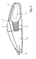
- a first housing 1 of a handheld vacuum cleaner according to one embodiment of the invention is shown.
- the first housing 1 includes a handle part located at a rear end of the vacuum cleaner and extending in a main handle direction being the longitudinal direction of the handheld vacuum cleaner.
- the handle part is provided with a through hole 3, which extends substantially perpendicular to main handle direction sideways between the left side and the right side of the vacuum cleaner.
- the through hole 3 is of oval shape and big enough to receive the fingers and a hand of an operator.
- the through hole 3 is lined with a frame element 4, which completely encircles the through hole 3.
- the frame element 4 is provided with one radially outward extending flange 5 respectively.
- the frame element 4 has a substantially U-shaped cross section along a top side, a rear side and a bottom side thereof.
- the frame element is provided with enforcement ribs 6.
- the first housing 1 further includes a top casing element 7 and a bottom casing element 8 of spoon-like shape.
- the top casing element 7 and the bottom casing element 8 each include a narrow handle attachment part 9 and a bowl-like housing part 10.
- the top casing element 7 and the bottom casing element 8, each are separate, integrated, one-piece plastic moulded elements.
- the bottom casing element is provided with two front end guiding tubes 13 and one rear end guiding tube 14.
- the first housing 1 includes a left casing part 11 and a right casing part 12.
- the left casing part 11 is located between the housing parts 9 of the top and bottom casing element 7, 8.
- the right casing part 12 is located between the housing parts 9 of the top and bottom casing element 7, 8.
- the right and left casing parts 11, 12 are connected to the frame element 4 at a front, the vacuum means facing end thereof.
- the left casing part 11 and the right casing part 12 are provided with through air holes for letting out exhaust air from the vacuum means.
- the frame element 4 including the hole encircling body, the flanges 5, the left casing part 11 and the right casing part 12, is an integrated, one-piece plastic moulded element.
- the frame element 4 When the first housing 1 of the vacuum cleaner is assembled, the frame element 4 is placed on the bottom casing element 8, and the top casing element 7 is placed on the frame element 4.
- the handle attachment part 9 of the top casing element 7 covers the top side and a top portion of the rear side of the hole encircling part of the frame element 4.
- the handle attachment part 9 of the bottom casing element 8 covers the bottom side and a bottom portion of the rear side of the hole encircling part of the frame element 4.
- the handle attachment parts 9 of the top and bottom casing element 7, 8 meet, such that the frame element 4 is embraced by the handle attachment parts 9.
- the vacuum cleaner comprises a second housing 17 accommodating a nozzle 16 and a debris collecting compartment.
- the second housing 17 is detachably connected to the first housing 1 for enabling emptying of the debris collecting compartment.
Landscapes
- Engineering & Computer Science (AREA)
- Mechanical Engineering (AREA)
- Electric Vacuum Cleaner (AREA)
- Filters For Electric Vacuum Cleaners (AREA)
Claims (10)
- Handstaubsauger, umfassend einen Griffteil, der sich in einer Hauptgriffrichtung erstreckt,
mit einem Durchgangsloch (3) zur Aufnahme eines oder mehrerer Finger eines Bedieners versehen ist, wobei sich das Durchgangsloch seitlich und im Wesentlichen senkrecht zur Hauptgriffrichtung erstreckt, und wobei der Griffteil
ein Rahmenelement (4) umfasst, das sich in der Hauptgriffrichtung erstreckt und das Durchgangsloch (3) umgibt,
wobei der Handstaubsauger ferner ein oberes Gehäuseelement (7) und ein unteres Gehäuseelement (8) umfasst,
wobei das Rahmenelement (4) ferner einen ersten Seitengehäuseteil (11) und einen zweiten Seitengehäuseteil (12) umfasst, die einen Seitenabschnitt an einer jeweiligen Seite des Staubsaugers zwischen dem oberen Gehäuseelement (7) und dem unteren Gehäuseelement (8) bilden und mit dem Rahmenelement (4) an einem dem Saugmittel zugewandten Ende davon verbunden sind,
wobei das Rahmenelement (4), das obere Gehäuseelement (7) und das untere Gehäuseelement (8) so angeordnet sind, dass sie ein Gehäuse zur Unterbringung mindestens eines Teils eines Saugmittels bilden,
wobei das obere Gehäuseelement (7) mit dem Rahmenelement (4) verbunden ist und mindestens einen Abschnitt der oberen Seite des Rahmenelements (4) abdeckt, und wobei
das untere Gehäuseelement (8) mit dem Rahmenelement (4) verbunden ist und mindestens einen Abschnitt der unteren Seite des Rahmenelements (4) abdeckt,
dadurch gekennzeichnet, dass
der erste Seitengehäuseteil (11) und der zweite Seitengehäuseteil (12) mit Durchgangsluftöffnungen für die Abluft des Saugmittels versehen sind. - Handstaubsauger nach Anspruch 1, wobei das Rahmenelement (4) ein durchgehendes, einteiliges Element ist, das das Durchgangsloch (3) umgibt.
- Handstaubsauger nach Anspruch 1 oder 2, wobei das Rahmenelement (4) entlang mindestens einem wesentlichen Abschnitt davon und an beiden Seiten des Lochs mit einem sich radial nach außen erstreckenden Flansch (5) versehen ist, so dass das Rahmenelement (4) einen im Wesentlichen U-förmigen Querschnitt entlang dem wesentlichen Abschnitt hat.
- Handstaubsauger nach einem der Ansprüche 1 - 3, wobei das Rahmenelement (4) ein im Wesentlichen ovales Durchgangsloch (3) umgibt.
- Handstaubsauger nach einem der Ansprüche 1 - 4, wobei das Rahmenelement (4), der erste Seitengehäuseteil (11) und der zweite Seitengehäuseteil (12) ein integrales, einteiliges Element sind.
- Handstaubsauger nach einem der Ansprüche 1 - 5, wobei das obere Gehäuseelement (7) mindestens einen Hauptabschnitt der oberen Seite des Rahmenelements (4) abdeckt und wobei das untere Gehäuseelement (8) mindestens einen Hauptabschnitt der unteren Seite des Rahmenelements (4) abdeckt.
- Handstaubsauger nach Anspruch 6, wobei das obere Gehäuseelement (7) und das untere Gehäuseelement (8) von einem dem Saugmittel zugewandten Ende des Rahmenelements (4) und im Wesentlichen in der Hauptgriffrichtung das Rahmenelement (4) umklammern und einander an einem dem Saugmittel gegenüberliegenden Ende des Rahmenelements (4) kontaktieren.
- Handstaubsauger nach einem der Ansprüche 1 - 7, wobei das obere Gehäuseelement (7) ein integrales, einteiliges Element ist und/oder das untere Gehäuseelement (8) ein integrales, einteiliges Element ist.
- Handstaubsauger nach einem der Ansprüche 1 - 8, wobei das Rahmenelement (4) mittels Schrauben (15) zwischen dem oberen Gehäuseelement (7) und dem unteren Gehäuseelement (8) eingeklemmt ist, wobei die Schrauben (15) in das untere Gehäuseelement eingeführt sind und in ein entsprechendes Gewinde im oberen Gehäuseelement eingeschraubt sind.
- Handstaubsauger nach einem der Ansprüche 1 - 9, wobei das Rahmenelement (4), das obere Gehäuseelement (7) und das untere Gehäuseelement (8) so angeordnet sind, dass sie ein erstes Gehäuse (1) zur Unterbringung eines Motors und eines Gebläses des Saugmittels bilden, wobei der Handstaubsauger ferner ein zweites Gehäuse (17) zur Unterbringung eines Abfallsammelfachs des Saugmittels und eine Düse umfasst und wobei das zweite Gehäuse an einem dem Saugmittel zugewandten Ende des ersten Gehäuses lösbar mit dem ersten Gehäuse verbunden ist.
Applications Claiming Priority (2)
| Application Number | Priority Date | Filing Date | Title |
|---|---|---|---|
| SE0601990 | 2006-09-25 | ||
| PCT/SE2007/000826 WO2008039127A1 (en) | 2006-09-25 | 2007-09-21 | Handheld vacuum cleaner |
Publications (3)
| Publication Number | Publication Date |
|---|---|
| EP2073680A1 EP2073680A1 (de) | 2009-07-01 |
| EP2073680A4 EP2073680A4 (de) | 2011-06-15 |
| EP2073680B1 true EP2073680B1 (de) | 2015-11-11 |
Family
ID=39230446
Family Applications (1)
| Application Number | Title | Priority Date | Filing Date |
|---|---|---|---|
| EP07835048.5A Not-in-force EP2073680B1 (de) | 2006-09-25 | 2007-09-21 | Handstaubsauger |
Country Status (4)
| Country | Link |
|---|---|
| US (1) | US8091168B2 (de) |
| EP (1) | EP2073680B1 (de) |
| CN (1) | CN101516246B (de) |
| WO (1) | WO2008039127A1 (de) |
Families Citing this family (12)
| Publication number | Priority date | Publication date | Assignee | Title |
|---|---|---|---|---|
| US20100192314A1 (en) * | 2009-02-03 | 2010-08-05 | Makita Corporation | Handy cleaners |
| DE102012100049B4 (de) * | 2012-01-04 | 2015-07-02 | Miele & Cie. Kg | Hand- oder Tischstaubsauger |
| CN103479293A (zh) * | 2013-09-30 | 2014-01-01 | 樊书印 | 一种微型吸尘器 |
| CN104274123B (zh) * | 2014-07-24 | 2017-03-15 | 莱克电气绿能科技(苏州)有限公司 | 一种床用吸尘器的装配定位机构 |
| CA2971070A1 (en) * | 2016-01-20 | 2017-07-20 | Jiangsu Midea Cleaning Appliances Co., Ltd. | Hand-held vacuum cleaner |
| EP3406172B1 (de) * | 2016-01-20 | 2023-05-03 | Jiangsu Midea Cleaning Appliances Co., Ltd. | Staubsauger |
| WO2017124631A1 (zh) * | 2016-01-20 | 2017-07-27 | 江苏美的清洁电器股份有限公司 | 吸尘器 |
| GB2563696B (en) * | 2017-06-19 | 2022-07-20 | Techtronic Floor Care Tech Ltd | Cyclonic separator device |
| JP7190628B2 (ja) | 2018-10-30 | 2022-12-16 | パナソニックIpマネジメント株式会社 | 電気掃除機 |
| US11690488B2 (en) | 2020-01-03 | 2023-07-04 | Techtronic Floor Care Technology Limited | Vacuum cleaner assembly |
| EP4559367B1 (de) | 2022-07-07 | 2026-04-22 | BISSELL Inc. | Modulares kopfsystem für handstaubsauger, trockenstaubsaugerzubehör für handstaubsauger und handstaubsauger |
| USD1047322S1 (en) * | 2023-03-17 | 2024-10-15 | Shenzhen Fanttik Technology | Handheld vacuum cleaner |
Family Cites Families (9)
| Publication number | Priority date | Publication date | Assignee | Title |
|---|---|---|---|---|
| US3513500A (en) * | 1967-03-01 | 1970-05-26 | Matsushita Electric Industrial Co Ltd | Compact hand vacuum cleaner |
| US4421964A (en) * | 1982-04-02 | 1983-12-20 | The Hoover Company | Remote switch actuation |
| KR890004768Y1 (ko) * | 1986-08-08 | 1989-07-20 | 산요덴끼 가부시기가이샤 | 전기 소제기 |
| US5065473A (en) * | 1989-01-09 | 1991-11-19 | Black & Decker Inc. | Filter assembly for a vacuum cleaner |
| US5379483A (en) * | 1992-07-21 | 1995-01-10 | Bissell, Inc. | Vacuum cleaner having a tool attached to the nozzle |
| US5638575A (en) * | 1995-05-24 | 1997-06-17 | Techtronic Industries Co., Ltd. | Vacuum cleaners |
| CN2495250Y (zh) * | 2001-07-19 | 2002-06-19 | 马美珍 | 外置式吸尘器电动滚动毛刷 |
| GB2377880A (en) * | 2001-07-25 | 2003-01-29 | Black & Decker Inc | Multi-operational battery powered vacuum cleaner |
| US20060090290A1 (en) * | 2004-11-01 | 2006-05-04 | Lau Ying W | Handheld vacuum with accelerated cyclonic flow and air freshener |
-
2007
- 2007-09-21 WO PCT/SE2007/000826 patent/WO2008039127A1/en not_active Ceased
- 2007-09-21 EP EP07835048.5A patent/EP2073680B1/de not_active Not-in-force
- 2007-09-21 US US12/442,854 patent/US8091168B2/en not_active Expired - Fee Related
- 2007-09-21 CN CN200780035664XA patent/CN101516246B/zh not_active Expired - Fee Related
Also Published As
| Publication number | Publication date |
|---|---|
| CN101516246B (zh) | 2012-05-30 |
| WO2008039127A1 (en) | 2008-04-03 |
| CN101516246A (zh) | 2009-08-26 |
| US20100088841A1 (en) | 2010-04-15 |
| US8091168B2 (en) | 2012-01-10 |
| EP2073680A1 (de) | 2009-07-01 |
| EP2073680A4 (de) | 2011-06-15 |
Similar Documents
| Publication | Publication Date | Title |
|---|---|---|
| EP2073680B1 (de) | Handstaubsauger | |
| JP7588648B2 (ja) | 別個の第1及び第2のハウジング部分を含む主ハウジングを有する手持ち式真空掃除機 | |
| RU2704561C2 (ru) | Пылесос | |
| RU2721763C2 (ru) | Пылесос | |
| US10561286B2 (en) | Configuration of a surface cleaning apparatus | |
| AU2016321998B2 (en) | Vacuum cleaner | |
| AU2016321999B2 (en) | Vacuum cleaner | |
| RU2488342C2 (ru) | Узел рукоятки для всасывающего узла | |
| JP5717464B2 (ja) | ブロワ | |
| JP2010512195A (ja) | 切り替え可能な表面清掃装置 | |
| US20160367093A1 (en) | Vacuum cleaner | |
| EP3525645B1 (de) | Saugwerkzeug für ein flächenreinigungsgerät | |
| EP2499952A1 (de) | Staubsaugerdüse | |
| CA2658497A1 (en) | Surface cleaning apparatus | |
| CA2658005A1 (en) | Configuration of a surface cleaning apparatus | |
| KR20190018532A (ko) | 배터리-작동식 진공 청소기 | |
| AU777603B2 (en) | Accessary tool mounting device for vacuum cleaner | |
| CA2578199C (en) | Ergonomic appliance handle | |
| US20060042046A1 (en) | Ergonomic appliance handle | |
| US6564423B2 (en) | Two piece upright handle assembly for a vacuum cleaner system | |
| EP3525648B1 (de) | Handgehaltenes oberflächenreinigungsgerät | |
| EP3525650B1 (de) | Oberflächenreinigungsgerät | |
| EP2928351B1 (de) | Staubsaugerhandgriff mit einem schlauchkupplungssystem | |
| EP3829405B1 (de) | Batteriebetriebener staubsauger | |
| JP7376460B2 (ja) | 電気掃除機 |
Legal Events
| Date | Code | Title | Description |
|---|---|---|---|
| PUAI | Public reference made under article 153(3) epc to a published international application that has entered the european phase |
Free format text: ORIGINAL CODE: 0009012 |
|
| 17P | Request for examination filed |
Effective date: 20090427 |
|
| AK | Designated contracting states |
Kind code of ref document: A1 Designated state(s): AT BE BG CH CY CZ DE DK EE ES FI FR GB GR HU IE IS IT LI LT LU LV MC MT NL PL PT RO SE SI SK TR |
|
| AX | Request for extension of the european patent |
Extension state: AL BA HR MK RS |
|
| A4 | Supplementary search report drawn up and despatched |
Effective date: 20110518 |
|
| DAX | Request for extension of the european patent (deleted) | ||
| 17Q | First examination report despatched |
Effective date: 20130104 |
|
| GRAP | Despatch of communication of intention to grant a patent |
Free format text: ORIGINAL CODE: EPIDOSNIGR1 |
|
| INTG | Intention to grant announced |
Effective date: 20150603 |
|
| GRAS | Grant fee paid |
Free format text: ORIGINAL CODE: EPIDOSNIGR3 |
|
| GRAA | (expected) grant |
Free format text: ORIGINAL CODE: 0009210 |
|
| AK | Designated contracting states |
Kind code of ref document: B1 Designated state(s): AT BE BG CH CY CZ DE DK EE ES FI FR GB GR HU IE IS IT LI LT LU LV MC MT NL PL PT RO SE SI SK TR |
|
| REG | Reference to a national code |
Ref country code: GB Ref legal event code: FG4D |
|
| REG | Reference to a national code |
Ref country code: CH Ref legal event code: EP |
|
| REG | Reference to a national code |
Ref country code: IE Ref legal event code: FG4D |
|
| REG | Reference to a national code |
Ref country code: AT Ref legal event code: REF Ref document number: 760005 Country of ref document: AT Kind code of ref document: T Effective date: 20151215 |
|
| REG | Reference to a national code |
Ref country code: DE Ref legal event code: R096 Ref document number: 602007043907 Country of ref document: DE |
|
| REG | Reference to a national code |
Ref country code: LT Ref legal event code: MG4D |
|
| REG | Reference to a national code |
Ref country code: NL Ref legal event code: MP Effective date: 20160211 |
|
| REG | Reference to a national code |
Ref country code: AT Ref legal event code: MK05 Ref document number: 760005 Country of ref document: AT Kind code of ref document: T Effective date: 20151111 |
|
| PG25 | Lapsed in a contracting state [announced via postgrant information from national office to epo] |
Ref country code: LT Free format text: LAPSE BECAUSE OF FAILURE TO SUBMIT A TRANSLATION OF THE DESCRIPTION OR TO PAY THE FEE WITHIN THE PRESCRIBED TIME-LIMIT Effective date: 20151111 Ref country code: ES Free format text: LAPSE BECAUSE OF FAILURE TO SUBMIT A TRANSLATION OF THE DESCRIPTION OR TO PAY THE FEE WITHIN THE PRESCRIBED TIME-LIMIT Effective date: 20151111 Ref country code: IT Free format text: LAPSE BECAUSE OF FAILURE TO SUBMIT A TRANSLATION OF THE DESCRIPTION OR TO PAY THE FEE WITHIN THE PRESCRIBED TIME-LIMIT Effective date: 20151111 Ref country code: NL Free format text: LAPSE BECAUSE OF FAILURE TO SUBMIT A TRANSLATION OF THE DESCRIPTION OR TO PAY THE FEE WITHIN THE PRESCRIBED TIME-LIMIT Effective date: 20151111 Ref country code: IS Free format text: LAPSE BECAUSE OF FAILURE TO SUBMIT A TRANSLATION OF THE DESCRIPTION OR TO PAY THE FEE WITHIN THE PRESCRIBED TIME-LIMIT Effective date: 20160311 |
|
| PG25 | Lapsed in a contracting state [announced via postgrant information from national office to epo] |
Ref country code: GR Free format text: LAPSE BECAUSE OF FAILURE TO SUBMIT A TRANSLATION OF THE DESCRIPTION OR TO PAY THE FEE WITHIN THE PRESCRIBED TIME-LIMIT Effective date: 20160212 Ref country code: LV Free format text: LAPSE BECAUSE OF FAILURE TO SUBMIT A TRANSLATION OF THE DESCRIPTION OR TO PAY THE FEE WITHIN THE PRESCRIBED TIME-LIMIT Effective date: 20151111 Ref country code: FI Free format text: LAPSE BECAUSE OF FAILURE TO SUBMIT A TRANSLATION OF THE DESCRIPTION OR TO PAY THE FEE WITHIN THE PRESCRIBED TIME-LIMIT Effective date: 20151111 Ref country code: PL Free format text: LAPSE BECAUSE OF FAILURE TO SUBMIT A TRANSLATION OF THE DESCRIPTION OR TO PAY THE FEE WITHIN THE PRESCRIBED TIME-LIMIT Effective date: 20151111 Ref country code: PT Free format text: LAPSE BECAUSE OF FAILURE TO SUBMIT A TRANSLATION OF THE DESCRIPTION OR TO PAY THE FEE WITHIN THE PRESCRIBED TIME-LIMIT Effective date: 20160311 Ref country code: AT Free format text: LAPSE BECAUSE OF FAILURE TO SUBMIT A TRANSLATION OF THE DESCRIPTION OR TO PAY THE FEE WITHIN THE PRESCRIBED TIME-LIMIT Effective date: 20151111 Ref country code: SE Free format text: LAPSE BECAUSE OF FAILURE TO SUBMIT A TRANSLATION OF THE DESCRIPTION OR TO PAY THE FEE WITHIN THE PRESCRIBED TIME-LIMIT Effective date: 20151111 |
|
| PG25 | Lapsed in a contracting state [announced via postgrant information from national office to epo] |
Ref country code: CZ Free format text: LAPSE BECAUSE OF FAILURE TO SUBMIT A TRANSLATION OF THE DESCRIPTION OR TO PAY THE FEE WITHIN THE PRESCRIBED TIME-LIMIT Effective date: 20151111 |
|
| REG | Reference to a national code |
Ref country code: DE Ref legal event code: R097 Ref document number: 602007043907 Country of ref document: DE |
|
| PG25 | Lapsed in a contracting state [announced via postgrant information from national office to epo] |
Ref country code: SK Free format text: LAPSE BECAUSE OF FAILURE TO SUBMIT A TRANSLATION OF THE DESCRIPTION OR TO PAY THE FEE WITHIN THE PRESCRIBED TIME-LIMIT Effective date: 20151111 Ref country code: DK Free format text: LAPSE BECAUSE OF FAILURE TO SUBMIT A TRANSLATION OF THE DESCRIPTION OR TO PAY THE FEE WITHIN THE PRESCRIBED TIME-LIMIT Effective date: 20151111 Ref country code: RO Free format text: LAPSE BECAUSE OF FAILURE TO SUBMIT A TRANSLATION OF THE DESCRIPTION OR TO PAY THE FEE WITHIN THE PRESCRIBED TIME-LIMIT Effective date: 20151111 Ref country code: EE Free format text: LAPSE BECAUSE OF FAILURE TO SUBMIT A TRANSLATION OF THE DESCRIPTION OR TO PAY THE FEE WITHIN THE PRESCRIBED TIME-LIMIT Effective date: 20151111 |
|
| PLBE | No opposition filed within time limit |
Free format text: ORIGINAL CODE: 0009261 |
|
| STAA | Information on the status of an ep patent application or granted ep patent |
Free format text: STATUS: NO OPPOSITION FILED WITHIN TIME LIMIT |
|
| REG | Reference to a national code |
Ref country code: FR Ref legal event code: PLFP Year of fee payment: 10 |
|
| 26N | No opposition filed |
Effective date: 20160812 |
|
| PG25 | Lapsed in a contracting state [announced via postgrant information from national office to epo] |
Ref country code: SI Free format text: LAPSE BECAUSE OF FAILURE TO SUBMIT A TRANSLATION OF THE DESCRIPTION OR TO PAY THE FEE WITHIN THE PRESCRIBED TIME-LIMIT Effective date: 20151111 |
|
| PG25 | Lapsed in a contracting state [announced via postgrant information from national office to epo] |
Ref country code: BE Free format text: LAPSE BECAUSE OF FAILURE TO SUBMIT A TRANSLATION OF THE DESCRIPTION OR TO PAY THE FEE WITHIN THE PRESCRIBED TIME-LIMIT Effective date: 20151111 |
|
| PG25 | Lapsed in a contracting state [announced via postgrant information from national office to epo] |
Ref country code: MC Free format text: LAPSE BECAUSE OF FAILURE TO SUBMIT A TRANSLATION OF THE DESCRIPTION OR TO PAY THE FEE WITHIN THE PRESCRIBED TIME-LIMIT Effective date: 20151111 |
|
| REG | Reference to a national code |
Ref country code: CH Ref legal event code: PL |
|
| REG | Reference to a national code |
Ref country code: IE Ref legal event code: MM4A |
|
| PG25 | Lapsed in a contracting state [announced via postgrant information from national office to epo] |
Ref country code: CH Free format text: LAPSE BECAUSE OF NON-PAYMENT OF DUE FEES Effective date: 20160930 Ref country code: LI Free format text: LAPSE BECAUSE OF NON-PAYMENT OF DUE FEES Effective date: 20160930 Ref country code: IE Free format text: LAPSE BECAUSE OF NON-PAYMENT OF DUE FEES Effective date: 20160921 |
|
| PG25 | Lapsed in a contracting state [announced via postgrant information from national office to epo] |
Ref country code: LU Free format text: LAPSE BECAUSE OF NON-PAYMENT OF DUE FEES Effective date: 20160921 |
|
| REG | Reference to a national code |
Ref country code: FR Ref legal event code: PLFP Year of fee payment: 11 |
|
| PG25 | Lapsed in a contracting state [announced via postgrant information from national office to epo] |
Ref country code: HU Free format text: LAPSE BECAUSE OF FAILURE TO SUBMIT A TRANSLATION OF THE DESCRIPTION OR TO PAY THE FEE WITHIN THE PRESCRIBED TIME-LIMIT; INVALID AB INITIO Effective date: 20070921 Ref country code: CY Free format text: LAPSE BECAUSE OF FAILURE TO SUBMIT A TRANSLATION OF THE DESCRIPTION OR TO PAY THE FEE WITHIN THE PRESCRIBED TIME-LIMIT Effective date: 20151111 |
|
| PG25 | Lapsed in a contracting state [announced via postgrant information from national office to epo] |
Ref country code: MT Free format text: LAPSE BECAUSE OF NON-PAYMENT OF DUE FEES Effective date: 20160930 Ref country code: TR Free format text: LAPSE BECAUSE OF FAILURE TO SUBMIT A TRANSLATION OF THE DESCRIPTION OR TO PAY THE FEE WITHIN THE PRESCRIBED TIME-LIMIT Effective date: 20151111 |
|
| PG25 | Lapsed in a contracting state [announced via postgrant information from national office to epo] |
Ref country code: BG Free format text: LAPSE BECAUSE OF FAILURE TO SUBMIT A TRANSLATION OF THE DESCRIPTION OR TO PAY THE FEE WITHIN THE PRESCRIBED TIME-LIMIT Effective date: 20151111 |
|
| REG | Reference to a national code |
Ref country code: FR Ref legal event code: PLFP Year of fee payment: 12 |
|
| PGFP | Annual fee paid to national office [announced via postgrant information from national office to epo] |
Ref country code: GB Payment date: 20220920 Year of fee payment: 16 Ref country code: DE Payment date: 20220920 Year of fee payment: 16 |
|
| PGFP | Annual fee paid to national office [announced via postgrant information from national office to epo] |
Ref country code: FR Payment date: 20220922 Year of fee payment: 16 |
|
| REG | Reference to a national code |
Ref country code: DE Ref legal event code: R119 Ref document number: 602007043907 Country of ref document: DE |
|
| GBPC | Gb: european patent ceased through non-payment of renewal fee |
Effective date: 20230921 |
|
| PG25 | Lapsed in a contracting state [announced via postgrant information from national office to epo] |
Ref country code: GB Free format text: LAPSE BECAUSE OF NON-PAYMENT OF DUE FEES Effective date: 20230921 |
|
| PG25 | Lapsed in a contracting state [announced via postgrant information from national office to epo] |
Ref country code: GB Free format text: LAPSE BECAUSE OF NON-PAYMENT OF DUE FEES Effective date: 20230921 Ref country code: FR Free format text: LAPSE BECAUSE OF NON-PAYMENT OF DUE FEES Effective date: 20230930 Ref country code: DE Free format text: LAPSE BECAUSE OF NON-PAYMENT OF DUE FEES Effective date: 20240403 |