EP2073971B1 - Maschine zur herstellung von papier-polstern - Google Patents
Maschine zur herstellung von papier-polstern Download PDFInfo
- Publication number
- EP2073971B1 EP2073971B1 EP07818509.7A EP07818509A EP2073971B1 EP 2073971 B1 EP2073971 B1 EP 2073971B1 EP 07818509 A EP07818509 A EP 07818509A EP 2073971 B1 EP2073971 B1 EP 2073971B1
- Authority
- EP
- European Patent Office
- Prior art keywords
- machine
- paper
- paper web
- hoop
- accordance
- Prior art date
- Legal status (The legal status is an assumption and is not a legal conclusion. Google has not performed a legal analysis and makes no representation as to the accuracy of the status listed.)
- Active
Links
Images

Classifications
-
- B—PERFORMING OPERATIONS; TRANSPORTING
- B31—MAKING ARTICLES OF PAPER, CARDBOARD OR MATERIAL WORKED IN A MANNER ANALOGOUS TO PAPER; WORKING PAPER, CARDBOARD OR MATERIAL WORKED IN A MANNER ANALOGOUS TO PAPER
- B31D—MAKING ARTICLES OF PAPER, CARDBOARD OR MATERIAL WORKED IN A MANNER ANALOGOUS TO PAPER, NOT PROVIDED FOR IN SUBCLASSES B31B OR B31C
- B31D5/00—Multiple-step processes for making three-dimensional [3D] articles
- B31D5/0039—Multiple-step processes for making three-dimensional [3D] articles for making dunnage or cushion pads
- B31D5/0043—Multiple-step processes for making three-dimensional [3D] articles for making dunnage or cushion pads including crumpling flat material
-
- B—PERFORMING OPERATIONS; TRANSPORTING
- B31—MAKING ARTICLES OF PAPER, CARDBOARD OR MATERIAL WORKED IN A MANNER ANALOGOUS TO PAPER; WORKING PAPER, CARDBOARD OR MATERIAL WORKED IN A MANNER ANALOGOUS TO PAPER
- B31D—MAKING ARTICLES OF PAPER, CARDBOARD OR MATERIAL WORKED IN A MANNER ANALOGOUS TO PAPER, NOT PROVIDED FOR IN SUBCLASSES B31B OR B31C
- B31D2205/00—Multiple-step processes for making three-dimensional articles
- B31D2205/0005—Multiple-step processes for making three-dimensional articles for making dunnage or cushion pads
- B31D2205/0011—Multiple-step processes for making three-dimensional articles for making dunnage or cushion pads including particular additional operations
- B31D2205/0017—Providing stock material in a particular form
- B31D2205/0023—Providing stock material in a particular form as web from a roll
-
- Y—GENERAL TAGGING OF NEW TECHNOLOGICAL DEVELOPMENTS; GENERAL TAGGING OF CROSS-SECTIONAL TECHNOLOGIES SPANNING OVER SEVERAL SECTIONS OF THE IPC; TECHNICAL SUBJECTS COVERED BY FORMER USPC CROSS-REFERENCE ART COLLECTIONS [XRACs] AND DIGESTS
- Y10—TECHNICAL SUBJECTS COVERED BY FORMER USPC
- Y10S—TECHNICAL SUBJECTS COVERED BY FORMER USPC CROSS-REFERENCE ART COLLECTIONS [XRACs] AND DIGESTS
- Y10S493/00—Manufacturing container or tube from paper; or other manufacturing from a sheet or web
- Y10S493/967—Dunnage, wadding, stuffing, or filling excelsior
Definitions
- the present invention relates to a machine for producing paper pads from a rolled up to a supply roll paper web, wherein the machine has a forming device for forming the paper web.
- a machine is out of the WO A-00/07808 and from the EP-A-1645406 known.
- the device produces from the roll of paper unwound from the supply roll a paper cushion with good cushioning properties and a low density, which can be used in particular for packaging shock-sensitive objects.
- the bracket contributes to the streamlining of the paper web and ensures a constant tension of the paper web, even if the supply roll only has a comparatively small diameter.
- the paper web runs down due to the inertia of the supply roll, and in this case, too, the yoke provides for an optimal running direction and a constant tension so that it does not tear when the machine is restarted the paper web is coming.
- the paper web is raised up to a certain extent by the weight of the bracket lying on it, that is, its angle of inclination with respect to the forming device is reduced, so that the entry into the forming device is improved.
- the forming device comprises a paper guide which can be adjusted in the conveying direction and on which the bow is pivotably mounted.
- the adjustability of the paper guide allows regulation of the width of the paper pad to be produced.
- a holder for holding the bracket is provided in its release position.
- Such a support prevents the bracket moves by gravity automatically from the release position to the pressure position, which would hinder the insertion of a supply roll in the machine.
- the forming device comprises an adjustable in the conveying direction Umformbügel.
- Umformbügel can support the curling of the paper web.
- the adjustability also provides a way to regulate the width of the paper pads to be made.
- the bracket is adjustably mounted in the conveying direction.
- the bracket is mounted on an adjustable in the conveying direction element of the forming device.
- the bracket can also be mounted independently of the forming device adjustable on a frame of the machine. In both cases, the adjustability of the strap makes it possible to influence the width of the paper pad to be produced.
- the machine for guiding the paper web has at least one deflection roller whose width is smaller than the width of the paper web.
- At least one deflection roller is provided, whose shaft is movably mounted in oblong holes, in particular against the force of a spring.
- a bearing of the pulleys in slots is indeed from the WO 00/07808 already known, however, burden in this prior art, the pulleys, which may also have a guiding function, the paper web exclusively due to its own weight.
- a spring is additionally provided, which biases the deflection roller in the oblong holes. In this way, the machine can also smoothly and quietly start when a very heavy supply roll is provided.
- the shaping device comprises a funnel-shaped shaft which tapers in the conveying direction, the size of the outlet opening of the shaft being adjustable.
- the size of the outlet opening can For example, serve pivotable wall portions of the shaft. When these are swung inward, the exit opening of the chute is reduced to produce narrower paper pads.
- the present invention is universally applicable and allows operation at both low and high processing speeds and with different types of paper.
- both very hard and stiff as well as soft papers can be processed with the machine according to the invention.
- the machine is particularly suitable for heavy stock rolls, high processing speeds and papers with low tear resistance.
- the pad to be produced with the machine according to the invention can be a single pad or even an endless pad.
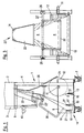
- Fig. 1 shows a machine for producing upholstery material or paper pads, the machine in a frame 1 and a Housing 2 is divided.
- the housing 2 provided with a control panel 3 there is a drive provided with a motor to pull a paper web 8 through a forming device 22, 22 'and 22 "and to form a pad from the paper web.
- the frame 1 consists essentially of a frame 4, two side plates 5 formed as end shields, which are mounted free-standing on the frame, and a carrier 6. To the frame 1 a plurality of wheels 7 are provided to move the machine.
- an arrangement for feeding the paper web 8 is mounted.
- the arrangement comprises a shaft 11 for a supply roll 12 with a paper web consisting of two paper layers. Further, mutually parallel guide rollers 13, 17 and 18 are provided, wherein the guide rollers 17 and 18 form a separator 14 to separate the paper layers.
- the shaft 11 of the supply roll 12 is mounted on the side parts 5 of the frame.
- the deflection rollers 13, 17 and 18 are each mounted with their shafts in a slot 16 which is arranged vertically in each side member 5 substantially.
- the separating device 14 comprises the deflection roller 17, which is in contact with the paper web 8 and serves to lift and deflect a paper layer, and the second deflection roller 18, which is intended to deflect the second paper layer.
- a further roller 19 is mounted in bores, which are formed in the side parts 5.
- the first deflection roller 17 rests on the roller 19 with the paper web 8 interposed therebetween.
- the deflection rollers 17, 18 of the separating device 14 have a smaller width than the paper web 8 Fig. 1 illustrated embodiment, the paper web 8 has a width of 74.0 cm, while the guide rollers 17, 18 only have a width of 71.5 cm. This will tear the paper web 8 prevents, especially when starting the machine after an interruption of production.
- Fig. 1 also shows, the waves of the pulleys 13, 17 and 18 within the slots against the force of springs 27 are movable.
- the forming device 22, 22 ', 22 “comprises a paper guide 22", which causes a rolling of the paper web at its outer edge regions.
- This paper guide 22 " is how Fig. 3 shows, mounted in slots 26 height adjustable on the frame 4. This height adjustment allows adaptation to the desired width of the paper pad. The higher the paper guide 22 "is pushed up in the slots 26, the wider the paper pad produced becomes.
- the paper guide 22 " is a Umformbügel 22 'is provided, which is also part of the forming device 22, 22', 22" and supports the curling of the paper web 8.
- the forming bracket 22 ' is height-adjustable mounted on the carrier 6, but can also be designed to be stationary.
- a funnel-shaped shaft 22 is provided which has a converging section with curved wall sections 24 on the narrow side.
- the curved wall portions 24 are pivotable to adjust the width of the paper tray 22 leaving the paper tray. With inwardly pivoted wall portions 24 narrower paper pads are made, while obtained by pivoting the wall sections 24 to the outside wider paper pad.
- Paper guide 22 "and the Umformbügels 22 ' allow the adjustable wall sections 24 a continuous adjustment of the width of the paper pad to be produced over a large area.
- bracket 30 On the paper guide 22 "is pivotally mounted a bracket 30, which is shown in the figures in a pressing position Fig. 2 detects, the bracket 30 is in this Andschreibposition over its entire width on the paper web 8.
- the bracket 30 thus supports the achieved by the spring-mounted pulley 18 tension of the outer paper layer of the paper web 8, as described in more detail below.
- a holder 40 is provided on the carrier 6, which has a recess for receiving the bracket 30.
- the bracket 30 can be pivoted from its pressure position shown in the figures in a release position, in which it is then held by the holder 40.
- the bracket 30 is first pivoted into its release position and latched into the holder 40.
- the bearing plates 5 are free-standing attached to the frame 1, so that the guide rollers 13, 17 and 18 and the roller 19 are freely accessible when the bracket 30 is in its release position, and a supply roll 12 inserted into the frame 1 can be.
- the provided with the shaft 11 supply roll 12 is as in Fig. 1 shown rolled on a provided for the storage of the shaft 11 recess. In this position, the supply roll 12 comes into contact with the brake band 20, so that unintentional unwinding of the paper web is prevented.
- the paper web 8 is subsequently introduced via the deflection roller 13 between the deflection roller 17 and the roller 19.
- the two paper layers of the paper web 8 are separated at the deflection rollers 17 and 18. Subsequently, the ends of the paper layers are introduced into the shaft 22. To reshape the Paper web serve not only the shaft 22, but also the forming bracket 22 'and the paper guide 22 ", which effect a lateral curling of the paper web in common cooperation with the shaft 22. Before the machine is put into operation, the bracket 30 is pivoted into its pressing position, then that the outer, over the guide roller 18 running paper layer of the paper web 8 is pressed by the weight of the bracket 30 in the direction of the inner, on the guide roller 17 running paper layer and additionally tightened.
- the guide roller 13 lies with its own weight on the paper web 8 in order to keep the paper web under tension.
- the pulleys 17 and 18 are also with their own weight on the paper web, on the one hand to stretch the individual paper layers and on the other hand to ensure a uniform supply of paper layers.
- the bracket 30 rests with its own weight on the outer paper layer and presses it in the direction of the inner paper layer. As a result, the angle of inclination of the outer paper layer is reduced, so that the introduction of the paper web 8 into the funnel-shaped shaft 22 is improved.
- the outer layer of the paper web 8 is additionally tightened, so that even with an already greatly reduced diameter of the supply roll or after stopping the machine is always ensured optimum tension of the paper web.
- the guide rollers 13, 17 and 18 are raised in the slots against the force of the springs 27, so that even with a heavy supply roll 12 a trouble-free starting is possible.
- the trouble-free starting is also supported by the fact that, as mentioned above, the width of the guide rollers 17, 18 of the separator 14 is selected to be lower than that Width of the paper web, so that it does not come to a tearing of the paper web 8, even if the paper web 8 breaks on the guide roller 18.
- Such a breaking of the paper web 8 can occur in particular when the supply roll 12 has only a comparatively small diameter, or when the machine is stopped in operation, and the paper web travels through the inertia of the supply roll 12, without the paper in the forming device 22, 22 ', 22 "is pulled in. In these cases, however, is prevented by the smaller width of the guide rollers 17, 18 and by the overlying bracket 30 that forms a paper bead on the outer guide roller 18, the re-starting the machine could cause a tearing of the paper web 8.
- the Fig. 2 shows another embodiment of the machine according to the invention, which is designed as a table model, but not in the functioning of the in Fig. 1 and machine described above differs.
- the machine also has a frame 1 with a frame 4 and side parts 5 for supporting the shaft 11 of the supply roll 12 and the guide rollers 13, 17, 18.
- the frame 1 is provided as in the embodiment described above with wheels 7, which here, however Brackets 31, 32 are mounted, so that the frame 1 is arranged inclined with respect to the horizontal.
- the guide roller 13 is mounted in the side parts 5 in a slot 33 which is formed parallel to the lower edge of the frame 1.
- the slot 33 can be formed so that it is arranged vertically to the support surface of the frame 1.
- the deflection rollers 17, 18 of the separator 14 are mounted in slots 34 which are arranged inclined with respect to the frame 4.
- the roller 19 is mounted in bores.
- the location of the Long hole 34 for supporting the guide roller 17 with respect to the bore of the bearing of the roller 19 is selected so that the guide roller 17 bears tangentially on the roller 19.
- a bracket 30 is also pivotally mounted in this embodiment on the paper guide 22 ", which in a in the Fig.
- a bracket for the bracket 30 is in Fig. 2 not shown, since the bracket can be placed in a release position on the support 6.
- the deflection rollers 17, 18 of the separating device 14 are also somewhat narrower than the paper web 8 in this embodiment.
Landscapes
- Replacement Of Web Rolls (AREA)
- Unwinding Webs (AREA)
- Registering, Tensioning, Guiding Webs, And Rollers Therefor (AREA)
Description
- Die vorliegende Erfindung betrifft eine Maschine zur Herstellung von Papier-Polstern aus einer zu einer Vorratsrolle aufgerollten Papierbahn, wobei die Maschine eine Umformeinrichtung zum Umformen der Papierbahn aufweist. Eine solche Maschine ist aus der
WO-A-00/07808 EP-A-1645406 bekannt. Die Vorrichtung stellt aus der von der Vorratsrolle abgerollten Papierbahn ein Papier-Polster mit guten Dämpfungseigenschaften und einer geringen Dichte her, welches insbesondere zum Verpacken stoßempfindlicher Gegenstände verwendet werden kann. - Aus der
US 2005/020427 A1 ist eine Maschine zur Herstellung von Papier-Polstern nach dem Oberbegriff des Anspruchs 1 bekannt. - Es ist die Aufgabe der Erfindung, eine Maschine der eingangs genannten Art so zu verbessern, dass auch bei hohen Fördergeschwindigkeiten und bei einem Anhalten während des Betriebs eine störungsfreie Herstellung von Papier-Polstern unterschiedlicher Formate ermöglicht wird.
- Die Lösung dieser Aufgabe erfolgt durch die Merkmale des Anspruchs.
- Der Bügel trägt zur Straffung der Papierbahn bei und sorgt für eine konstante Spannung der Papierbahn auch dann, wenn die Vorratsrolle nur noch einen vergleichsweise geringen Durchmesser aufweist. Wenn die Maschine während des Betriebs angehalten wird, läuft die Papierbahn aufgrund der Trägheit der Vorratsrolle nach, und auch in diesem Fall sorgt der Bügel für eine optimale Laufrichtung und eine konstante Spannung, so dass es beim erneuten Start der Maschine nicht zu einem Einreißen der Papierbahn kommt. Zudem wird die Papierbahn durch das Gewicht des auf ihr liegenden Bügels gewissermaßen aufgerichtet, das heißt, ihr Neigungswinkel in Bezug auf die Umformeinrichtung wird verringert, so dass der Einzug in die Umformeinrichtung verbessert wird.
- Die Umformeinrichtung umfasst eine in Förderrichtung verstellbare Papierführung, an der der Bügel schwenkbar gelagert ist. Die Verstellbarkeit der Papierführung ermöglicht eine Regulierung der Breite der herzustellenden Papier-Polster. Wenn der Bügel an dieser verstellbaren Papierführung gelagert ist, wird seine Position automatisch ebenfalls an die gewünschte Breite der Papier-Polster angepasst.
- Vorteilhafte Ausführungsformen der Erfindung sind in der Beschreibung, den Ansprüchen und den Zeichnungen beschrieben.
- Nach einer ersten vorteilhaften Ausführungsform ist eine Halterung zum Halten des Bügels in seiner Freigabeposition vorgesehen. Eine solche Halterung verhindert, dass der Bügel sich durch die Schwerkraft selbsttätig von der Freigabeposition in die Andrückposition bewegt, was das Einlegen einer Vorratsrolle in die Maschine behindern würde.
- Vorteilhafterweise umfasst die Umformeinrichtung einen in Förderrichtung verstellbaren Umformbügel. Ein solcher Umformbügel kann das Einrollen der Papierbahn unterstützen. Die Verstellbarkeit bietet ebenfalls eine Möglichkeit, die Breite der herzustellenden Papier-Polster zu regulieren.
- Nach einer weiteren vorteilhaften Ausführungsform der Erfindung ist der Bügel in Förderrichtung verstellbar gelagert. Dies kann entweder, wie oben bereits erwähnt, dadurch realisiert werden, dass der Bügel an einem in Förderrichtung verstellbaren Element der Umformeinrichtung gelagert wird. Der Bügel kann aber selbstverständlich auch unabhängig von der Umformeinrichtung verstellbar an einem Gestell der Maschine gelagert sein. In beiden Fällen wird durch die Verstellbarkeit des Bügels eine Beeinflussung der Breite der herzustellenden Papier-Polster ermöglicht.
- Gemäß einer bevorzugten Ausführungsform der Erfindung weist die Maschine zur Führung der Papierbahn zumindest eine Umlenkrolle auf, deren Breite geringer ist als die Breite der Papierbahn. Dadurch wird ein Einreißen der Papierbahn insbesondere beim Anfahren der Maschine auch dann verhindert, wenn die Papierbahn nicht optimal gespannt ist.
- Vorzugsweise ist wenigstens eine Umlenkrolle vorgesehen, deren Welle in Langlöchern insbesondere gegen die Kraft einer Feder beweglich gelagert ist. Eine Lagerung der Umlenkrollen in Langlöchern ist zwar aus der
WO 00/07808 - Gemäß einer bevorzugten Ausführungsform der Erfindung umfasst die Umformeinrichtung einen sich in Förderrichtung verjüngenden trichterförmigen Schacht, wobei die Größe der Ausgangsöffnung des Schachtes verstellbar ist. Zum Verstellen der Größe der Ausgangsöffnung können beispielsweise verschwenkbare Wandbereiche des Schachtes dienen. Wenn diese nach innen verschwenkt werden, wird die Ausgangsöffnung des Schachtes verkleinert, so dass schmalere Papier-Polster produziert werden.
- Die vorliegende Erfindung ist universell einsetzbar und erlaubt einen Betrieb sowohl bei niedrigen als auch bei hohen Verarbeitungsgeschwindigkeiten und mit unterschiedlichen Papiersorten. So können sowohl sehr harte und steife als auch weiche Papiere mit der erfindungsgemäßen Maschine verarbeitet werden. Ganz besonders eignet sich die Maschine für schwere Vorratsrollen, hohe Verarbeitungsgeschwindigkeiten und Papiere mit niedriger Reißfestigkeit. Die mit der erfindungsgemäßen Maschine herzustellenden Polster können Einzelpolster oder aber auch Endlospolster sein.
- Nachfolgend wird die vorliegende Erfindung rein beispielhaft anhand vorteilhafter Ausführungsformen und unter Bezugnahme auf die beigefügten Zeichnungen beschrieben. Es zeigen:
- Fig. 1
- eine schematische Darstellung einer Maschine zur Herstellung von Papier-Polstern;
- Fig. 2
- eine schematische Darstellung einer weiteren Maschine zur Herstellung von Papier-Polstern; und
- Fig. 3
- eine schematische Darstellung der Maschine aus
Fig. 1 aus einer anderen Perspektive. -
Fig. 1 zeigt eine Maschine zur Herstellung von polsterartigem Material bzw. von Papier-Polstern, wobei die Maschine in ein Gestell 1 und ein Gehäuse 2 unterteilt ist. In dem mit einer Steuertafel 3 versehenen Gehäuse 2 befindet sich ein mit einem Motor versehener Antrieb, um eine Papierbahn 8 durch eine Umformeinrichtung 22, 22' und 22" zu ziehen und aus der Papierbahn ein Polster zu formen. - Das Gestell 1 besteht im Wesentlichen aus einem Rahmen 4, zwei als Lagerschilde ausgebildeten Seitenteilen 5, die freistehend am Gestell befestigt sind, und einem Träger 6. An dem Gestell 1 sind mehrere Räder 7 vorgesehen, um die Maschine zu verfahren.
- In dem Gestell 1 ist eine Anordnung zum Zuführen der Papierbahn 8 montiert. Die Anordnung umfasst eine Welle 11 für eine Vorratsrolle 12 mit einer aus zwei Papierlagen bestehenden Papierbahn. Ferner sind zueinander parallele Umlenkrollen 13, 17 und 18 vorgesehen, wobei die Umlenkrollen 17 und 18 eine Trenneinrichtung 14 bilden, um die Papierlagen zu trennen. Die Welle 11 der Vorratsrolle 12 ist an den Seitenteilen 5 des Gestells gelagert. Die Umlenkrollen 13, 17 und 18 sind mit ihren Wellen jeweils in einem Langloch 16 gelagert, das in jedem Seitenteil 5 im Wesentlichen vertikal angeordnet ist. Die Trenneinrichtung 14 umfasst die Umlenkrolle 17, die mit der Papierbahn 8 in Kontakt steht, und dazu dient, eine Papierlage abzuheben und umzulenken, sowie die zweite Umlenkrolle 18, die dazu bestimmt ist, die zweite Papierlage umzulenken. Ferner ist eine weitere Rolle 19 in Bohrungen gelagert, die in den Seitenteilen 5 ausgebildet sind. Die erste Umlenkrolle 17 liegt unter Zwischenlage der Papierbahn 8 auf der Rolle 19 auf. Die Umlenkrollen 17, 18 der Trenneinrichtung 14 besitzen eine geringere Breite als die Papierbahn 8. Bei dem in
Fig. 1 dargestellten Ausführungsbeispiel besitzt die Papierbahn 8 eine Breite von 74,0 cm, während die Umlenkrollen 17, 18 lediglich eine Breite von 71,5 cm aufweisen. Dadurch wird ein Einreißen der Papierbahn 8 verhindert, insbesondere bei einem Anfahren der Maschine nach einer Unterbrechung der Produktion. - Wie
Fig. 1 ferner zeigt, sind die Wellen der Umlenkrollen 13, 17 und 18 innerhalb der Langlöcher gegen die Kraft von Federn 27 bewegbar. - Am Außenumfang der Vorratsrolle 12 liegt ein Bremsband 20 mit einem Bremsbelag 21 an, das aus Federstahl besteht.
- Die Umformeinrichtung 22, 22', 22" umfasst eine Papierführung 22", die ein Einrollen der Papierbahn an ihren äußeren Randbereichen bewirkt. Diese Papierführung 22" ist, wie
Fig. 3 zeigt, in Langlöchern 26 höhenverstellbar an dem Rahmen 4 gelagert. Diese Höhenverstellbarkeit erlaubt eine Anpassung an die gewünschte Breite des Papier-Polsters. Je höher die Papierführung 22" in den Langlöchern 26 nach oben geschoben ist, desto breiter wird das hergestellte Papier-Polster. - Oberhalb von der Papierführung 22" ist ein Umformbügel 22' vorgesehen, welcher ebenfalls Bestandteil der Umformeinrichtung 22, 22', 22" ist und das Einrollen der Papierbahn 8 unterstützt. Der Umformbügel 22' ist höhenverstellbar an dem Träger 6 gelagert, kann aber auch feststehend ausgebildet sein. Zum Einführen der Papierlagen in das Gehäuse 2 ist ein trichterförmiger Schacht 22 vorgesehen, der an der Schmalseite einen konvergierenden Abschnitt mit gekrümmten Wandabschnitten 24 aufweist. Wie in
Fig. 3 erkennbar ist, sind die gekrümmten Wandabschnitte 24 verschwenkbar, um die Breite der den Schacht 22 verlassenden Papier-Polster zu verstellen. Bei nach innen geschwenkten Wandabschnitten 24 werden schmalere Papier-Polster hergestellt, während man durch ein Verschwenken der Wandabschnitte 24 nach außen breitere Papier-Polster erhält. Zusammen mit der oben beschriebenen Höhenverstellbarkeit der Papierführung 22" und des Umformbügels 22' erlauben die verstellbaren Wandabschnitte 24 eine stufenlose Einstellung der Breite der herzustellenden Papier-Polster über einen großen Bereich. - An der Papierführung 22" ist verschwenkbar ein Bügel 30 gelagert, der in den Figuren in einer Andrückposition gezeigt ist. Wie man insbesondere in
Fig. 2 erkennt, liegt der Bügel 30 in dieser Andrückposition über seine gesamte Breite auf der Papierbahn 8 auf. Der Bügel 30 unterstützt somit die durch die federnd gelagerte Umlenkrolle 18 erzielte Spannung der äußeren Papierlage der Papierbahn 8, wie unten näher beschrieben wird. Auf der Höhe des trichterförmigen Schachtes 22 ist an dem Träger 6 eine Halterung 40 vorgesehen, welche eine Ausnehmung zur Aufnahme des Bügels 30 besitzt. Der Bügel 30 kann aus seiner in den Figuren dargestellten Andrückposition in eine Freigabeposition verschwenkt werden, in der er dann von der Halterung 40 gehalten wird. - Zur Vorbereitung des Betriebs wird zunächst der Bügel 30 in seine Freigabeposition verschwenkt und in die Halterung 40 eingeklinkt. Wie bereits erwähnt, sind die Lagerschilde 5 freistehend am Gestell 1 befestigt, so dass die Umlenkrollen 13, 17 und 18 und die Rolle 19 frei zugänglich sind, wenn der Bügel 30 sich in seiner Freigabeposition befindet, und eine Vorratsrolle 12 in das Gestell 1 eingelegt werden kann. Die mit der Welle 11 versehene Vorratsrolle 12 wird wie in
Fig. 1 dargestellt auf eine für die Lagerung der Welle 11 vorgesehene Aussparung gerollt. In dieser Stellung kommt die Vorratsrolle 12 mit dem Bremsband 20 in Kontakt, so dass ein ungewolltes Abwickeln der Papierbahn verhindert wird. Die Papierbahn 8 wird anschließend über die Umlenkrolle 13 zwischen die Umlenkrolle 17 und die Rolle 19 eingeführt. Die beiden Papierlagen der Papierbahn 8 werden an den Umlenkrollen 17 und 18 getrennt. Anschließend werden die Enden der Papierlagen in den Schacht 22 eingeführt. Zum Umformen der Papierbahn dienen dabei nicht nur der Schacht 22, sondern auch der Umformbügel 22' und die Papierführung 22", die im gemeinsamen Zusammenwirken mit dem Schacht 22 ein seitliches Einrollen der Papierbahn bewirken. Vor Inbetriebnahme der Maschine wird der Bügel 30 in seine Andrückposition verschwenkt, so dass die äußere, über die Umlenkrolle 18 laufende Papierlage der Papierbahn 8 von dem Gewicht des Bügels 30 in Richtung der inneren, über die Umlenkrolle 17 laufenden Papierlage gedrückt und zusätzlich gestrafft wird. - Nachfolgend wird die Funktionsweise der vorstehend beschriebenen Maschine erläutert.
- Während des Betriebs liegt die Umlenkrolle 13 mit ihrem Eigengewicht auf der Papierbahn 8, um die Papierbahn unter Spannung zu halten. Die Umlenkrollen 17 und 18 liegen ebenfalls mit ihrem Eigengewicht auf der Papierbahn, um einerseits die einzelnen Papierlagen zu spannen und andererseits eine gleichmäßige Zuführung der Papierlagen zu gewährleisten. Der Bügel 30 liegt mit seinem Eigengewicht auf der äußeren Papierlage auf und drückt diese in Richtung der inneren Papierlage. Dadurch wird der Neigungswinkel der äußeren Papierlage verringert, so dass die Einfuhr der Papierbahn 8 in den trichterförmigen Schacht 22 verbessert wird. Zudem wird die äußere Lage der Papierbahn 8 zusätzlich gestrafft, so dass auch bei einem bereits stark verringerten Durchmesser der Vorratsrolle oder nach einem Anhalten der Maschine immer für eine optimale Spannung der Papierbahn gesorgt ist. Beim Anfahren der Vorrichtung können die Führungsrollen 13, 17 und 18 in den Langlöchern gegen die Kraft der Federn 27 angehoben werden, so dass auch bei einer schweren Vorratsrolle 12 ein störungsfreies Anfahren möglich ist. Das störungsfreie Anfahren wird zudem dadurch unterstützt, dass, wie oben erwähnt, die Breite der Umlenkrollen 17, 18 der Trenneinrichtung 14 geringer gewählt ist als die Breite der Papierbahn, so dass es auch dann, wenn die Papierbahn 8 an der Umlenkrolle 18 ausbricht, nicht zu einem Einreißen der Papierbahn 8 kommt. Ein solches Ausbrechen der Papierbahn 8 kann insbesondere dann auftreten, wenn die Vorratsrolle 12 nur noch einen vergleichsweise kleinen Durchmesser besitzt, oder wenn die Maschine im Betrieb angehalten wird, und die Papierbahn durch die Trägheit der Vorratsrolle 12 nachläuft, ohne dass das Papier in die Umformeinrichtung 22, 22', 22" eingezogen wird. In diesen Fällen wird aber durch die geringere Breite der Umlenkrollen 17, 18 und durch den aufliegenden Bügel 30 verhindert, dass sich an der äußeren Umlenkrolle 18 ein Papierwulst bildet, der beim erneuten Starten der Maschine zu einem Einreißen der Papierbahn 8 führen könnte.
- Die
Fig. 2 zeigt eine andere Ausführungsform der erfindungsgemäßen Maschine, die als Tischmodell ausgeführt ist, sich in der Funktionsweise aber nicht von der inFig. 1 dargestellten und oben beschriebenen Maschine unterscheidet. Die Maschine besitzt ebenfalls ein Gestell 1 mit einem Rahmen 4 und Seitenteilen 5 zur Lagerung der Welle 11 der Vorratsrolle 12 sowie der Umlenkrollen 13, 17, 18. Das Gestell 1 ist wie in der oben beschriebenen Ausführungsform mit Rädern 7 versehen, die hier allerdings an Haltern 31, 32 montiert sind, so dass das Gestell 1 geneigt bezüglich der Horizontalen angeordnet ist. In der Anordnung der Umlenkrollen 13, 17, 18 in den Seitenteilen 5 unterscheidet sich die inFig. 2 dargestellte Maschine von der oben beschriebenen Maschine. Die Umlenkrolle 13 ist in den Seitenteilen 5 in einem Langloch 33 gelagert, welches parallel zur Unterkante des Gestells 1 ausgebildet ist. Das Langloch 33 kann so ausgebildet werden, dass es vertikal zur Auflagefläche des Gestells 1 angeordnet ist. Die Umlenkrollen 17, 18 der Trenneinrichtung 14 sind in Langlöchern 34 gelagert, die in Bezug auf den Rahmen 4 geneigt angeordnet sind. Die Rolle 19 ist in Bohrungen gelagert. Die Lage des Langloches 34 zur Lagerung der Umlenkrolle 17 bezüglich der Bohrung der Lagerung der Rolle 19 ist so gewählt, dass die Umlenkrolle 17 tangential an der Rolle 19 anliegt. Die Umformeinrichtung 22, 22', 22" entspricht der oben für die inFig. 1 dargestellte Maschine beschriebenen Umformeinrichtung. Wie oben beschrieben, ist auch bei dieser Ausführungsform an der Papierführung 22" verschwenkbar ein Bügel 30 gelagert, welcher in einer in derFig. 2 dargestellten Andrückposition die über die Umlenkrolle 18 laufende äußere Papierlage in Richtung der inneren Papierlage andrückt. Eine Halterung für den Bügel 30 ist inFig. 2 nicht dargestellt, da der Bügel in einer Freigabeposition auf den Träger 6 aufgelegt werden kann. Die Umlenkrollen 17, 18 der Trenneinrichtung 14 sind auch bei dieser Ausführungsform etwas schmaler als die Papierbahn 8. -
- 1
- Gestell
- 2
- Gehäuse
- 3
- Steuertafel
- 5
- Seitenteil
- 6
- Träger
- 7
- Räder
- 8
- Papierbahn
- 11
- Welle
- 12
- Vorratsrolle
- 13
- Umlenkrolle
- 14
- Trenneinrichtung
- 16
- Langloch
- 17
- Umlenkrolle
- 18
- Umlenkrolle
- 19
- Rolle
- 20
- Bremsband
- 21
- Bremsbelag
- 22
- Schacht
- 22'
- Umformbügel
- 22"
- Papierführung
- 23
- Austrittsöffnung
- 24
- Wandabschnitt
- 26
- Langloch
- 27
- Feder
- 30
- Bügel
- 31, 32
- Halter
- 33, 34
- Langloch
Claims (7)
- Maschine zur Herstellung von Papier-Polstern aus einer zu einer Vorratsrolle (12) aufgerollten Papierbahn (8), wobei die Maschine eine Umformeinrichtung (22, 22', 22") zum Umformen der Papierbahn (8) aufweist,
wobei in einem Bereich vor dem Eintritt der Papierbahn (8) in die Umformeinrichtung (22, 22', 22") ein zwischen einer Andrückposition und einer Freigabeposition verschwenkbarer Bügel (30) vorgesehen ist, der in der Andrückposition auf der Papierbahn (8) aufliegt, dadurch gekennzeichnet, dass die Umformeinrichtung (22, 22', 22") eine in Förderrichtung verstellbare Papierführung (22") umfasst, an der der Bügel (30) schwenkbar gelagert ist. - Maschine nach Anspruch 1,
dadurch gekennzeichnet, dass eine Halterung (40) zum Halten des Bügels (30) in seiner Freigabeposition vorgesehen ist. - Maschine nach zumindest einem der vorstehenden Ansprüche, dadurch gekennzeichnet, dass die Umformeinrichtung (22, 22', 22") einen in Förderrichtung verstellbaren Umformbügel (22') umfasst.
- Maschine nach zumindest einem der vorstehenden Ansprüche, dadurch gekennzeichnet, dass der Bügel (30) in Förderrichtung verstellbar gelagert ist.
- Maschine nach zumindest einem der vorstehenden Ansprüche, dadurch gekennzeichnet, dass sie zur Führung der Papierbahn (8) zumindest eine Umlenkrolle (13, 17, 18) aufweist, deren Breite geringer ist als die Breite der Papierbahn (8).
- Maschine nach zumindest einem der vorstehenden Ansprüche, dadurch gekennzeichnet, dass wenigstens eine Umlenkrolle (13, 17, 18) vorgesehen ist, deren Welle in Langlöchern (16) insbesondere gegen die Kraft einer Feder (27) beweglich gelagert ist.
- Maschine nach zumindest einem der vorstehenden Ansprüche, dadurch gekennzeichnet, dass die Umformeinrichtung (22, 22' 22") einen sich in Förderrichtung verjüngenden trichterförmigen Schacht (22) umfasst, wobei die Größe der Ausgangsöffnung (23) des Schachtes (22) verstellbar ist.
Applications Claiming Priority (2)
| Application Number | Priority Date | Filing Date | Title |
|---|---|---|---|
| DE102006059638A DE102006059638A1 (de) | 2006-12-18 | 2006-12-18 | Maschine zur Herstellung von Papier-Polstern |
| PCT/EP2007/008426 WO2008074372A1 (de) | 2006-12-18 | 2007-09-27 | Machine zur herstellung von papier-polstern |
Publications (2)
| Publication Number | Publication Date |
|---|---|
| EP2073971A1 EP2073971A1 (de) | 2009-07-01 |
| EP2073971B1 true EP2073971B1 (de) | 2016-11-09 |
Family
ID=38627037
Family Applications (1)
| Application Number | Title | Priority Date | Filing Date |
|---|---|---|---|
| EP07818509.7A Active EP2073971B1 (de) | 2006-12-18 | 2007-09-27 | Maschine zur herstellung von papier-polstern |
Country Status (6)
| Country | Link |
|---|---|
| US (1) | US8920299B2 (de) |
| EP (1) | EP2073971B1 (de) |
| BR (1) | BRPI0720357A2 (de) |
| DE (1) | DE102006059638A1 (de) |
| ES (1) | ES2614639T3 (de) |
| WO (1) | WO2008074372A1 (de) |
Families Citing this family (8)
| Publication number | Priority date | Publication date | Assignee | Title |
|---|---|---|---|---|
| DE102012218682A1 (de) * | 2012-10-12 | 2014-04-17 | Storopack Hans Reichenecker Gmbh | Vorrichtung zur Herstellung eines Polsterungsprodukts aus Papier |
| EP2969841B1 (de) | 2013-03-15 | 2017-08-30 | Ranpak Corp. | Packmaterialumwandlungsmaschine, spiralförmig verdrehtes packmaterialprodukt und verfahren |
| DE102013015866B4 (de) | 2013-09-23 | 2019-12-12 | Sprick Gmbh Bielefelder Papier- Und Wellpappenwerke & Co. | Abrollsystem für eine Rolle Papier sowie für eine Füllmaterialfertigungsmaschine |
| JP6956011B2 (ja) * | 2015-05-13 | 2021-10-27 | ランパク コーポレーション | ストック供給アセンブリ及びダンネージ転換機に充填する方法 |
| FR3061072B1 (fr) * | 2016-12-22 | 2020-02-07 | Jacky Peterlini | Dispositif de distribution d'element de calage et d'emballage |
| DE102017109330A1 (de) * | 2017-05-02 | 2018-11-08 | Storopack Hans Reichenecker Gmbh | Vorrichtung zur Bereitstellung von Polstermaterial für Verpackungszwecke, sowie Umformungseinheit für eine solche Vorrichtung |
| FR3100742B1 (fr) * | 2019-09-17 | 2021-08-06 | Jacky Peterlini | Dispositif de production d’element de calage |
| WO2022212110A1 (en) | 2021-03-30 | 2022-10-06 | Sealed Air Corporation (Us) | Molding cushioning products from converted sheet material |
Family Cites Families (17)
| Publication number | Priority date | Publication date | Assignee | Title |
|---|---|---|---|---|
| US3603216A (en) * | 1970-02-09 | 1971-09-07 | Arpax Co | Method for producing cushioning dunnage |
| US4717613A (en) * | 1984-05-10 | 1988-01-05 | Ranpak Corporation | Mechanism and method for producing cushioning dunnage |
| US5755656A (en) * | 1995-06-07 | 1998-05-26 | Ranpak Corp. | Cushioning conversion machine and method with independent edge connecting |
| ES2093502T3 (es) | 1994-04-22 | 1996-12-16 | Naturembal Sa | Procedimiento y maquina de fabricacion de materiales de relleno por arrugado de papel. |
| US6190299B1 (en) * | 1995-03-24 | 2001-02-20 | Ranpak Corporation | Cushion producing machine |
| JPH11506988A (ja) * | 1995-06-07 | 1999-06-22 | ランパック コーポレイション | クッション変換機のローディングアッセンブリーおよび方法 |
| US6019715A (en) * | 1995-06-26 | 2000-02-01 | Ranpak Corp. | Cushioning conversion machine and method |
| AU8593598A (en) * | 1997-07-28 | 1999-02-16 | Ranpak Corp. | Cushioning conversion machine with power infeed |
| JP4336450B2 (ja) * | 1997-09-18 | 2009-09-30 | ランパック コーポレイション | 荷敷パッド製造および包装システム |
| DE69908551T2 (de) * | 1998-01-12 | 2004-04-22 | Ranpak Corp., Concord Township | Maschine und verfahren zum herstellen von polsterelementen |
| AU4766799A (en) | 1998-08-04 | 2000-02-28 | Reinhard Keller | Device for feeding paper webs used by a machine producing a padding-like packaging material, and machine with such device |
| CA2385238A1 (en) * | 2000-06-19 | 2001-12-27 | Ranpak Corp. | Cushioning conversion machine and method |
| EP1197321A3 (de) * | 2000-09-14 | 2003-04-16 | Ranpak Corp. | Polsterumwandlungsmaschine mit Vorrichtung zum bremsen der Vorratsrolle und Verfahren zur deren Benutzung |
| EP2799223A3 (de) * | 2003-07-07 | 2014-12-31 | Ranpak Corp. | Polstermaterialwandler und Verfahren ohne Schneidevorrichtung |
| DE602005017185D1 (de) * | 2004-08-20 | 2009-11-26 | Ranpak Corp | Maschine und verfahren zur herstellung von polsterelementen |
| EP1645406A1 (de) * | 2005-02-17 | 2006-04-12 | Reinhard Keller | Maschine zur Herstellung von Papier-Polstern |
| US8167783B2 (en) * | 2006-04-11 | 2012-05-01 | Pack-Tiger Gmbh | Machine for the manufacture of paper padding |
-
2006
- 2006-12-18 DE DE102006059638A patent/DE102006059638A1/de not_active Withdrawn
-
2007
- 2007-09-27 BR BRPI0720357-8A2A patent/BRPI0720357A2/pt not_active Application Discontinuation
- 2007-09-27 ES ES07818509.7T patent/ES2614639T3/es active Active
- 2007-09-27 WO PCT/EP2007/008426 patent/WO2008074372A1/de not_active Ceased
- 2007-09-27 US US12/516,556 patent/US8920299B2/en active Active
- 2007-09-27 EP EP07818509.7A patent/EP2073971B1/de active Active
Also Published As
| Publication number | Publication date |
|---|---|
| DE102006059638A1 (de) | 2008-06-19 |
| US20100300639A1 (en) | 2010-12-02 |
| US8920299B2 (en) | 2014-12-30 |
| EP2073971A1 (de) | 2009-07-01 |
| ES2614639T3 (es) | 2017-06-01 |
| WO2008074372A1 (de) | 2008-06-26 |
| BRPI0720357A2 (pt) | 2014-04-08 |
Similar Documents
| Publication | Publication Date | Title |
|---|---|---|
| EP2073971A1 (de) | Machine zur herstellung von papier-polstern | |
| DE69405151T2 (de) | Gerät zum Schneiden einer Materialbahn auf bestimmte Länge und zum Ausgeben derselben | |
| DE69305274T2 (de) | Maschine und Verfahren zur Fertigung von kernlosen Rollen von Bahnmaterial | |
| EP2073972A1 (de) | Maschine zur herstellung von papier-polstern | |
| DE69710826T2 (de) | Vorrichtung zum Verbreiten einer Bahn | |
| DE2842226C2 (de) | Vorrichtung und Verfahren zum weiteren Längsfalzen von mit einem Querbruch versehenen, mehrblättrigen Zeitungen | |
| EP1845046B1 (de) | Falzanleger mit Vorrichtung zum Rillen des Bogens | |
| EP3642144B1 (de) | Vorrichtung zur bereitstellung eines spulenförmigen polsterungsprodukts für verpackungszwecke | |
| EP0792829A2 (de) | Verfahren und Vorrichtung zum Aufwickeln einer Papierbahn zu einer Rolle | |
| DE602005004168T2 (de) | Packmaterialumwandlungsmaschine mit gleitenden führungen | |
| DE102018110595A1 (de) | Verfahren und Vorrichtung zur Herstellung eines Verpackungspolsters | |
| DE69804965T2 (de) | Polsterkonvertierungsmaschine mit mechanischer zufuhr | |
| EP2053001A1 (de) | Verfahren zum Auflockern eines aus Blättern gebildeten Stapels, insbesondere eines Papierstapels, sowie Vorrichtung zur Durchführung des Verfahrens | |
| EP3737630A1 (de) | Vorrichtung zum schneiden einer materialbahn in einzelne bögen mit einem bahnspeicher | |
| DE102013104978A1 (de) | Maschine zum Aufwickeln von bahnförmigen Materialien | |
| EP1064147B1 (de) | Anordnung zum zuführen von papierbahnen für eine maschine zur herstellung von polsterartigem verpackungsmaterial und maschine mit einer derartigen anordnung | |
| DE19704332B4 (de) | Vorrichtung zum Bearbeiten von mindestens zwei Materialbahnen aus Papier oder Kunststoffolie | |
| EP1832536A1 (de) | Einrichtung zur Verarbeitung und/oder zum Transport von flachen Versandstücken | |
| EP1072515B1 (de) | Vorrichtung zum Abwickeln von Band in einer Umreifungsmaschine | |
| DE10332711B4 (de) | Riemen für Wickelvorrichtung | |
| DE3539591C2 (de) | ||
| EP2719527A1 (de) | Vorrichtung zur Herstellung eines Polsterungsprodukts aus Papier | |
| DE102006018769B3 (de) | Vorrichtung zum Transport bogenförmiger flacher Gegenstände | |
| DE960072C (de) | Unterriemchen-Streckwerk fuer Spinn- und Vorspinnmaschinen | |
| EP2082982B1 (de) | Wickelvorrichtung |
Legal Events
| Date | Code | Title | Description |
|---|---|---|---|
| PUAI | Public reference made under article 153(3) epc to a published international application that has entered the european phase |
Free format text: ORIGINAL CODE: 0009012 |
|
| 17P | Request for examination filed |
Effective date: 20090327 |
|
| AK | Designated contracting states |
Kind code of ref document: A1 Designated state(s): AT BE BG CH CY CZ DE DK EE ES FI FR GB GR HU IE IS IT LI LT LU LV MC MT NL PL PT RO SE SI SK TR |
|
| AX | Request for extension of the european patent |
Extension state: AL BA HR MK RS |
|
| RIN1 | Information on inventor provided before grant (corrected) |
Inventor name: KELLER, REINHARD |
|
| DAX | Request for extension of the european patent (deleted) | ||
| 17Q | First examination report despatched |
Effective date: 20160303 |
|
| GRAP | Despatch of communication of intention to grant a patent |
Free format text: ORIGINAL CODE: EPIDOSNIGR1 |
|
| INTG | Intention to grant announced |
Effective date: 20160511 |
|
| GRAS | Grant fee paid |
Free format text: ORIGINAL CODE: EPIDOSNIGR3 |
|
| GRAA | (expected) grant |
Free format text: ORIGINAL CODE: 0009210 |
|
| AK | Designated contracting states |
Kind code of ref document: B1 Designated state(s): AT BE BG CH CY CZ DE DK EE ES FI FR GB GR HU IE IS IT LI LT LU LV MC MT NL PL PT RO SE SI SK TR |
|
| REG | Reference to a national code |
Ref country code: GB Ref legal event code: FG4D Free format text: NOT ENGLISH |
|
| REG | Reference to a national code |
Ref country code: AT Ref legal event code: REF Ref document number: 843511 Country of ref document: AT Kind code of ref document: T Effective date: 20161115 Ref country code: CH Ref legal event code: EP |
|
| REG | Reference to a national code |
Ref country code: IE Ref legal event code: FG4D Free format text: LANGUAGE OF EP DOCUMENT: GERMAN |
|
| REG | Reference to a national code |
Ref country code: DE Ref legal event code: R096 Ref document number: 502007015252 Country of ref document: DE |
|
| PG25 | Lapsed in a contracting state [announced via postgrant information from national office to epo] |
Ref country code: LV Free format text: LAPSE BECAUSE OF FAILURE TO SUBMIT A TRANSLATION OF THE DESCRIPTION OR TO PAY THE FEE WITHIN THE PRESCRIBED TIME-LIMIT Effective date: 20161109 |
|
| REG | Reference to a national code |
Ref country code: LT Ref legal event code: MG4D |
|
| REG | Reference to a national code |
Ref country code: NL Ref legal event code: MP Effective date: 20161109 |
|
| PG25 | Lapsed in a contracting state [announced via postgrant information from national office to epo] |
Ref country code: LT Free format text: LAPSE BECAUSE OF FAILURE TO SUBMIT A TRANSLATION OF THE DESCRIPTION OR TO PAY THE FEE WITHIN THE PRESCRIBED TIME-LIMIT Effective date: 20161109 Ref country code: GR Free format text: LAPSE BECAUSE OF FAILURE TO SUBMIT A TRANSLATION OF THE DESCRIPTION OR TO PAY THE FEE WITHIN THE PRESCRIBED TIME-LIMIT Effective date: 20170210 Ref country code: SE Free format text: LAPSE BECAUSE OF FAILURE TO SUBMIT A TRANSLATION OF THE DESCRIPTION OR TO PAY THE FEE WITHIN THE PRESCRIBED TIME-LIMIT Effective date: 20161109 Ref country code: NL Free format text: LAPSE BECAUSE OF FAILURE TO SUBMIT A TRANSLATION OF THE DESCRIPTION OR TO PAY THE FEE WITHIN THE PRESCRIBED TIME-LIMIT Effective date: 20161109 |
|
| PG25 | Lapsed in a contracting state [announced via postgrant information from national office to epo] |
Ref country code: PL Free format text: LAPSE BECAUSE OF FAILURE TO SUBMIT A TRANSLATION OF THE DESCRIPTION OR TO PAY THE FEE WITHIN THE PRESCRIBED TIME-LIMIT Effective date: 20161109 Ref country code: FI Free format text: LAPSE BECAUSE OF FAILURE TO SUBMIT A TRANSLATION OF THE DESCRIPTION OR TO PAY THE FEE WITHIN THE PRESCRIBED TIME-LIMIT Effective date: 20161109 Ref country code: IS Free format text: LAPSE BECAUSE OF FAILURE TO SUBMIT A TRANSLATION OF THE DESCRIPTION OR TO PAY THE FEE WITHIN THE PRESCRIBED TIME-LIMIT Effective date: 20170309 Ref country code: PT Free format text: LAPSE BECAUSE OF FAILURE TO SUBMIT A TRANSLATION OF THE DESCRIPTION OR TO PAY THE FEE WITHIN THE PRESCRIBED TIME-LIMIT Effective date: 20170309 |
|
| REG | Reference to a national code |
Ref country code: ES Ref legal event code: FG2A Ref document number: 2614639 Country of ref document: ES Kind code of ref document: T3 Effective date: 20170601 |
|
| PG25 | Lapsed in a contracting state [announced via postgrant information from national office to epo] |
Ref country code: CZ Free format text: LAPSE BECAUSE OF FAILURE TO SUBMIT A TRANSLATION OF THE DESCRIPTION OR TO PAY THE FEE WITHIN THE PRESCRIBED TIME-LIMIT Effective date: 20161109 Ref country code: EE Free format text: LAPSE BECAUSE OF FAILURE TO SUBMIT A TRANSLATION OF THE DESCRIPTION OR TO PAY THE FEE WITHIN THE PRESCRIBED TIME-LIMIT Effective date: 20161109 Ref country code: SK Free format text: LAPSE BECAUSE OF FAILURE TO SUBMIT A TRANSLATION OF THE DESCRIPTION OR TO PAY THE FEE WITHIN THE PRESCRIBED TIME-LIMIT Effective date: 20161109 Ref country code: RO Free format text: LAPSE BECAUSE OF FAILURE TO SUBMIT A TRANSLATION OF THE DESCRIPTION OR TO PAY THE FEE WITHIN THE PRESCRIBED TIME-LIMIT Effective date: 20161109 Ref country code: DK Free format text: LAPSE BECAUSE OF FAILURE TO SUBMIT A TRANSLATION OF THE DESCRIPTION OR TO PAY THE FEE WITHIN THE PRESCRIBED TIME-LIMIT Effective date: 20161109 |
|
| REG | Reference to a national code |
Ref country code: DE Ref legal event code: R097 Ref document number: 502007015252 Country of ref document: DE |
|
| PG25 | Lapsed in a contracting state [announced via postgrant information from national office to epo] |
Ref country code: BG Free format text: LAPSE BECAUSE OF FAILURE TO SUBMIT A TRANSLATION OF THE DESCRIPTION OR TO PAY THE FEE WITHIN THE PRESCRIBED TIME-LIMIT Effective date: 20170209 |
|
| PLBE | No opposition filed within time limit |
Free format text: ORIGINAL CODE: 0009261 |
|
| STAA | Information on the status of an ep patent application or granted ep patent |
Free format text: STATUS: NO OPPOSITION FILED WITHIN TIME LIMIT |
|
| REG | Reference to a national code |
Ref country code: FR Ref legal event code: PLFP Year of fee payment: 11 |
|
| 26N | No opposition filed |
Effective date: 20170810 |
|
| PG25 | Lapsed in a contracting state [announced via postgrant information from national office to epo] |
Ref country code: SI Free format text: LAPSE BECAUSE OF FAILURE TO SUBMIT A TRANSLATION OF THE DESCRIPTION OR TO PAY THE FEE WITHIN THE PRESCRIBED TIME-LIMIT Effective date: 20161109 |
|
| REG | Reference to a national code |
Ref country code: CH Ref legal event code: PL |
|
| PG25 | Lapsed in a contracting state [announced via postgrant information from national office to epo] |
Ref country code: MC Free format text: LAPSE BECAUSE OF FAILURE TO SUBMIT A TRANSLATION OF THE DESCRIPTION OR TO PAY THE FEE WITHIN THE PRESCRIBED TIME-LIMIT Effective date: 20161109 |
|
| REG | Reference to a national code |
Ref country code: IE Ref legal event code: MM4A |
|
| REG | Reference to a national code |
Ref country code: BE Ref legal event code: MM Effective date: 20170930 |
|
| PG25 | Lapsed in a contracting state [announced via postgrant information from national office to epo] |
Ref country code: LU Free format text: LAPSE BECAUSE OF NON-PAYMENT OF DUE FEES Effective date: 20170927 |
|
| PG25 | Lapsed in a contracting state [announced via postgrant information from national office to epo] |
Ref country code: LI Free format text: LAPSE BECAUSE OF NON-PAYMENT OF DUE FEES Effective date: 20170930 Ref country code: CH Free format text: LAPSE BECAUSE OF NON-PAYMENT OF DUE FEES Effective date: 20170930 Ref country code: IE Free format text: LAPSE BECAUSE OF NON-PAYMENT OF DUE FEES Effective date: 20170927 |
|
| PG25 | Lapsed in a contracting state [announced via postgrant information from national office to epo] |
Ref country code: BE Free format text: LAPSE BECAUSE OF NON-PAYMENT OF DUE FEES Effective date: 20170930 |
|
| REG | Reference to a national code |
Ref country code: FR Ref legal event code: PLFP Year of fee payment: 12 |
|
| PG25 | Lapsed in a contracting state [announced via postgrant information from national office to epo] |
Ref country code: MT Free format text: LAPSE BECAUSE OF FAILURE TO SUBMIT A TRANSLATION OF THE DESCRIPTION OR TO PAY THE FEE WITHIN THE PRESCRIBED TIME-LIMIT Effective date: 20161109 |
|
| REG | Reference to a national code |
Ref country code: AT Ref legal event code: MM01 Ref document number: 843511 Country of ref document: AT Kind code of ref document: T Effective date: 20170927 |
|
| PG25 | Lapsed in a contracting state [announced via postgrant information from national office to epo] |
Ref country code: AT Free format text: LAPSE BECAUSE OF NON-PAYMENT OF DUE FEES Effective date: 20170927 |
|
| PG25 | Lapsed in a contracting state [announced via postgrant information from national office to epo] |
Ref country code: HU Free format text: LAPSE BECAUSE OF FAILURE TO SUBMIT A TRANSLATION OF THE DESCRIPTION OR TO PAY THE FEE WITHIN THE PRESCRIBED TIME-LIMIT; INVALID AB INITIO Effective date: 20070927 |
|
| PG25 | Lapsed in a contracting state [announced via postgrant information from national office to epo] |
Ref country code: CY Free format text: LAPSE BECAUSE OF NON-PAYMENT OF DUE FEES Effective date: 20161109 |
|
| PG25 | Lapsed in a contracting state [announced via postgrant information from national office to epo] |
Ref country code: TR Free format text: LAPSE BECAUSE OF FAILURE TO SUBMIT A TRANSLATION OF THE DESCRIPTION OR TO PAY THE FEE WITHIN THE PRESCRIBED TIME-LIMIT Effective date: 20161109 |
|
| P01 | Opt-out of the competence of the unified patent court (upc) registered |
Effective date: 20230425 |
|
| PGFP | Annual fee paid to national office [announced via postgrant information from national office to epo] |
Ref country code: DE Payment date: 20250926 Year of fee payment: 19 |
|
| PGFP | Annual fee paid to national office [announced via postgrant information from national office to epo] |
Ref country code: IT Payment date: 20250922 Year of fee payment: 19 |
|
| PGFP | Annual fee paid to national office [announced via postgrant information from national office to epo] |
Ref country code: GB Payment date: 20250923 Year of fee payment: 19 |
|
| PGFP | Annual fee paid to national office [announced via postgrant information from national office to epo] |
Ref country code: FR Payment date: 20250925 Year of fee payment: 19 |
|
| PGFP | Annual fee paid to national office [announced via postgrant information from national office to epo] |
Ref country code: ES Payment date: 20251015 Year of fee payment: 19 |