EP2073975B1 - Système de formation de couches de renforcement présentant des fibres orientées transversalement - Google Patents
Système de formation de couches de renforcement présentant des fibres orientées transversalement Download PDFInfo
- Publication number
- EP2073975B1 EP2073975B1 EP07836959A EP07836959A EP2073975B1 EP 2073975 B1 EP2073975 B1 EP 2073975B1 EP 07836959 A EP07836959 A EP 07836959A EP 07836959 A EP07836959 A EP 07836959A EP 2073975 B1 EP2073975 B1 EP 2073975B1
- Authority
- EP
- European Patent Office
- Prior art keywords
- fibers
- chopped
- array
- continuous fibers
- nozzle
- Prior art date
- Legal status (The legal status is an assumption and is not a legal conclusion. Google has not performed a legal analysis and makes no representation as to the accuracy of the status listed.)
- Not-in-force
Links
- 239000000835 fiber Substances 0.000 title claims description 297
- 230000002787 reinforcement Effects 0.000 title claims description 40
- 239000000463 material Substances 0.000 claims description 32
- 239000012530 fluid Substances 0.000 claims description 19
- 238000000034 method Methods 0.000 claims description 17
- 230000008021 deposition Effects 0.000 claims description 9
- 239000004744 fabric Substances 0.000 claims description 7
- 239000011230 binding agent Substances 0.000 claims description 5
- 239000006185 dispersion Substances 0.000 claims 2
- 239000011248 coating agent Substances 0.000 claims 1
- 238000000576 coating method Methods 0.000 claims 1
- 239000003365 glass fiber Substances 0.000 description 8
- 229920005989 resin Polymers 0.000 description 7
- 239000011347 resin Substances 0.000 description 7
- 239000002131 composite material Substances 0.000 description 5
- 230000003247 decreasing effect Effects 0.000 description 3
- 239000002657 fibrous material Substances 0.000 description 3
- 238000004519 manufacturing process Methods 0.000 description 3
- 229920000049 Carbon (fiber) Polymers 0.000 description 2
- 229920000271 Kevlar® Polymers 0.000 description 2
- 239000004917 carbon fiber Substances 0.000 description 2
- JBKVHLHDHHXQEQ-UHFFFAOYSA-N epsilon-caprolactam Chemical compound O=C1CCCCCN1 JBKVHLHDHHXQEQ-UHFFFAOYSA-N 0.000 description 2
- 239000002557 mineral fiber Substances 0.000 description 2
- 229920000728 polyester Polymers 0.000 description 2
- 239000007921 spray Substances 0.000 description 2
- 239000004593 Epoxy Substances 0.000 description 1
- 239000004760 aramid Substances 0.000 description 1
- 229920006231 aramid fiber Polymers 0.000 description 1
- 238000003491 array Methods 0.000 description 1
- 229920001400 block copolymer Polymers 0.000 description 1
- 238000005056 compaction Methods 0.000 description 1
- 238000005137 deposition process Methods 0.000 description 1
- 238000009826 distribution Methods 0.000 description 1
- 229920001971 elastomer Polymers 0.000 description 1
- 239000000806 elastomer Substances 0.000 description 1
- 238000009730 filament winding Methods 0.000 description 1
- 239000007789 gas Substances 0.000 description 1
- 239000011521 glass Substances 0.000 description 1
- 238000010438 heat treatment Methods 0.000 description 1
- 238000005470 impregnation Methods 0.000 description 1
- 238000001746 injection moulding Methods 0.000 description 1
- 239000007788 liquid Substances 0.000 description 1
- 238000000465 moulding Methods 0.000 description 1
- ISWSIDIOOBJBQZ-UHFFFAOYSA-N phenol group Chemical group C1(=CC=CC=C1)O ISWSIDIOOBJBQZ-UHFFFAOYSA-N 0.000 description 1
- 229920001568 phenolic resin Polymers 0.000 description 1
- 229920000647 polyepoxide Polymers 0.000 description 1
- 229920001225 polyester resin Polymers 0.000 description 1
- 229920000642 polymer Polymers 0.000 description 1
- 229920005749 polyurethane resin Polymers 0.000 description 1
- 230000003014 reinforcing effect Effects 0.000 description 1
- 239000012783 reinforcing fiber Substances 0.000 description 1
- 238000003892 spreading Methods 0.000 description 1
- 238000004381 surface treatment Methods 0.000 description 1
- 229920001169 thermoplastic Polymers 0.000 description 1
- 239000004634 thermosetting polymer Substances 0.000 description 1
- 239000004416 thermosoftening plastic Substances 0.000 description 1
- 238000001721 transfer moulding Methods 0.000 description 1
Images

Classifications
-
- B—PERFORMING OPERATIONS; TRANSPORTING
- B32—LAYERED PRODUCTS
- B32B—LAYERED PRODUCTS, i.e. PRODUCTS BUILT-UP OF STRATA OF FLAT OR NON-FLAT, e.g. CELLULAR OR HONEYCOMB, FORM
- B32B5/00—Layered products characterised by the non- homogeneity or physical structure, i.e. comprising a fibrous, filamentary, particulate or foam layer; Layered products characterised by having a layer differing constitutionally or physically in different parts
- B32B5/22—Layered products characterised by the non- homogeneity or physical structure, i.e. comprising a fibrous, filamentary, particulate or foam layer; Layered products characterised by having a layer differing constitutionally or physically in different parts characterised by the presence of two or more layers which are next to each other and are fibrous, filamentary, formed of particles or foamed
- B32B5/24—Layered products characterised by the non- homogeneity or physical structure, i.e. comprising a fibrous, filamentary, particulate or foam layer; Layered products characterised by having a layer differing constitutionally or physically in different parts characterised by the presence of two or more layers which are next to each other and are fibrous, filamentary, formed of particles or foamed one layer being a fibrous or filamentary layer
- B32B5/26—Layered products characterised by the non- homogeneity or physical structure, i.e. comprising a fibrous, filamentary, particulate or foam layer; Layered products characterised by having a layer differing constitutionally or physically in different parts characterised by the presence of two or more layers which are next to each other and are fibrous, filamentary, formed of particles or foamed one layer being a fibrous or filamentary layer another layer next to it also being fibrous or filamentary
-
- B—PERFORMING OPERATIONS; TRANSPORTING
- B29—WORKING OF PLASTICS; WORKING OF SUBSTANCES IN A PLASTIC STATE IN GENERAL
- B29C—SHAPING OR JOINING OF PLASTICS; SHAPING OF MATERIAL IN A PLASTIC STATE, NOT OTHERWISE PROVIDED FOR; AFTER-TREATMENT OF THE SHAPED PRODUCTS, e.g. REPAIRING
- B29C70/00—Shaping composites, i.e. plastics material comprising reinforcements, fillers or preformed parts, e.g. inserts
- B29C70/04—Shaping composites, i.e. plastics material comprising reinforcements, fillers or preformed parts, e.g. inserts comprising reinforcements only, e.g. self-reinforcing plastics
- B29C70/06—Fibrous reinforcements only
- B29C70/10—Fibrous reinforcements only characterised by the structure of fibrous reinforcements, e.g. hollow fibres
- B29C70/12—Fibrous reinforcements only characterised by the structure of fibrous reinforcements, e.g. hollow fibres using fibres of short length, e.g. in the form of a mat
- B29C70/14—Fibrous reinforcements only characterised by the structure of fibrous reinforcements, e.g. hollow fibres using fibres of short length, e.g. in the form of a mat oriented
-
- B—PERFORMING OPERATIONS; TRANSPORTING
- B29—WORKING OF PLASTICS; WORKING OF SUBSTANCES IN A PLASTIC STATE IN GENERAL
- B29C—SHAPING OR JOINING OF PLASTICS; SHAPING OF MATERIAL IN A PLASTIC STATE, NOT OTHERWISE PROVIDED FOR; AFTER-TREATMENT OF THE SHAPED PRODUCTS, e.g. REPAIRING
- B29C70/00—Shaping composites, i.e. plastics material comprising reinforcements, fillers or preformed parts, e.g. inserts
- B29C70/04—Shaping composites, i.e. plastics material comprising reinforcements, fillers or preformed parts, e.g. inserts comprising reinforcements only, e.g. self-reinforcing plastics
- B29C70/06—Fibrous reinforcements only
- B29C70/10—Fibrous reinforcements only characterised by the structure of fibrous reinforcements, e.g. hollow fibres
- B29C70/16—Fibrous reinforcements only characterised by the structure of fibrous reinforcements, e.g. hollow fibres using fibres of substantial or continuous length
- B29C70/20—Fibrous reinforcements only characterised by the structure of fibrous reinforcements, e.g. hollow fibres using fibres of substantial or continuous length oriented in a single direction, e.g. roofing or other parallel fibres
-
- B—PERFORMING OPERATIONS; TRANSPORTING
- B29—WORKING OF PLASTICS; WORKING OF SUBSTANCES IN A PLASTIC STATE IN GENERAL
- B29C—SHAPING OR JOINING OF PLASTICS; SHAPING OF MATERIAL IN A PLASTIC STATE, NOT OTHERWISE PROVIDED FOR; AFTER-TREATMENT OF THE SHAPED PRODUCTS, e.g. REPAIRING
- B29C70/00—Shaping composites, i.e. plastics material comprising reinforcements, fillers or preformed parts, e.g. inserts
- B29C70/04—Shaping composites, i.e. plastics material comprising reinforcements, fillers or preformed parts, e.g. inserts comprising reinforcements only, e.g. self-reinforcing plastics
- B29C70/06—Fibrous reinforcements only
- B29C70/10—Fibrous reinforcements only characterised by the structure of fibrous reinforcements, e.g. hollow fibres
- B29C70/16—Fibrous reinforcements only characterised by the structure of fibrous reinforcements, e.g. hollow fibres using fibres of substantial or continuous length
- B29C70/20—Fibrous reinforcements only characterised by the structure of fibrous reinforcements, e.g. hollow fibres using fibres of substantial or continuous length oriented in a single direction, e.g. roofing or other parallel fibres
- B29C70/202—Fibrous reinforcements only characterised by the structure of fibrous reinforcements, e.g. hollow fibres using fibres of substantial or continuous length oriented in a single direction, e.g. roofing or other parallel fibres arranged in parallel planes or structures of fibres crossing at substantial angles, e.g. cross-moulding compound [XMC]
-
- B—PERFORMING OPERATIONS; TRANSPORTING
- B32—LAYERED PRODUCTS
- B32B—LAYERED PRODUCTS, i.e. PRODUCTS BUILT-UP OF STRATA OF FLAT OR NON-FLAT, e.g. CELLULAR OR HONEYCOMB, FORM
- B32B5/00—Layered products characterised by the non- homogeneity or physical structure, i.e. comprising a fibrous, filamentary, particulate or foam layer; Layered products characterised by having a layer differing constitutionally or physically in different parts
- B32B5/02—Layered products characterised by the non- homogeneity or physical structure, i.e. comprising a fibrous, filamentary, particulate or foam layer; Layered products characterised by having a layer differing constitutionally or physically in different parts characterised by structural features of a fibrous or filamentary layer
- B32B5/06—Layered products characterised by the non- homogeneity or physical structure, i.e. comprising a fibrous, filamentary, particulate or foam layer; Layered products characterised by having a layer differing constitutionally or physically in different parts characterised by structural features of a fibrous or filamentary layer characterised by a fibrous or filamentary layer mechanically connected, e.g. by needling to another layer, e.g. of fibres, of paper
-
- B—PERFORMING OPERATIONS; TRANSPORTING
- B32—LAYERED PRODUCTS
- B32B—LAYERED PRODUCTS, i.e. PRODUCTS BUILT-UP OF STRATA OF FLAT OR NON-FLAT, e.g. CELLULAR OR HONEYCOMB, FORM
- B32B5/00—Layered products characterised by the non- homogeneity or physical structure, i.e. comprising a fibrous, filamentary, particulate or foam layer; Layered products characterised by having a layer differing constitutionally or physically in different parts
- B32B5/02—Layered products characterised by the non- homogeneity or physical structure, i.e. comprising a fibrous, filamentary, particulate or foam layer; Layered products characterised by having a layer differing constitutionally or physically in different parts characterised by structural features of a fibrous or filamentary layer
- B32B5/08—Layered products characterised by the non- homogeneity or physical structure, i.e. comprising a fibrous, filamentary, particulate or foam layer; Layered products characterised by having a layer differing constitutionally or physically in different parts characterised by structural features of a fibrous or filamentary layer the fibres or filaments of a layer being of different substances, e.g. conjugate fibres, mixture of different fibres
-
- B—PERFORMING OPERATIONS; TRANSPORTING
- B32—LAYERED PRODUCTS
- B32B—LAYERED PRODUCTS, i.e. PRODUCTS BUILT-UP OF STRATA OF FLAT OR NON-FLAT, e.g. CELLULAR OR HONEYCOMB, FORM
- B32B38/00—Ancillary operations in connection with laminating processes
- B32B38/18—Handling of layers or the laminate
- B32B2038/1891—Using a robot for handling the layers
-
- Y—GENERAL TAGGING OF NEW TECHNOLOGICAL DEVELOPMENTS; GENERAL TAGGING OF CROSS-SECTIONAL TECHNOLOGIES SPANNING OVER SEVERAL SECTIONS OF THE IPC; TECHNICAL SUBJECTS COVERED BY FORMER USPC CROSS-REFERENCE ART COLLECTIONS [XRACs] AND DIGESTS
- Y10—TECHNICAL SUBJECTS COVERED BY FORMER USPC
- Y10T—TECHNICAL SUBJECTS COVERED BY FORMER US CLASSIFICATION
- Y10T428/00—Stock material or miscellaneous articles
- Y10T428/24—Structurally defined web or sheet [e.g., overall dimension, etc.]
- Y10T428/24058—Structurally defined web or sheet [e.g., overall dimension, etc.] including grain, strips, or filamentary elements in respective layers or components in angular relation
- Y10T428/24124—Fibers
Definitions
- the present invention relates generally to a system for forming reinforcement layers having cross-directionally oriented fibers, and, particularly, to a system for the dispensing of both continuous fibers and chopped reinforcement fibers to form the reinforcement layers.
- the present invention has industrial applicability for making fiber reinforced articles, mats or preforms that are suitable for reinforcing molded articles, such as structural composites, pipes and the like.
- Structural composites and other reinforced molded articles are commonly made using manufacturing processes such as resin transfer molding and structural resin injection molding. These molding processes have been made more efficient by using reinforcement fibers that arc used to make a reinforcement layer or mat.
- the preformed fiber reinforced layers or mat "preforms" or filament winding prepregs have the approximate shape and size of the molded article.
- US 2005/008804 describes a method of making a fibrous material bv providing a first longitudinal layer of glass fibers, applying an intermediate layer of reinforcing fibers onto the first layer (at least same of which include at least portions thereof which extend in the transverse direction), and covering the intermediate layer with a second longitudinal layer of glass fibers.
- US 2002/124936 describes a method of making composite sheets using two bundles of composite parallel threads and a lap of composite threads deposited transversely in the form of a mat having continuous threads.
- WO 03/038331 describes a reinforcement liner made of a fabric material and methods of making the liner and fabric material. The fabric material is formed as a continuous strip of materials by providing at first longitudinal layer of glass fibers and applying a second layer comprising chopped fibers extending in a direction substantially perpendicular to the fibers in the first layer.
- reinforcement fibers As the technical requirements for reinforcement products increases, new methods for dispensing and laying down reinforcement fibers are required. One requirement is that the reinforcement fibers be delivered at faster speeds than used previously. Another requirement is that the reinforcement fibers be laid down in varying degrees of thickness or density to achieve the desired reinforcement result. Another requirement is that the reinforcement fibers be laid down in a predetermined orientation.
- the preforms When preforms are made with specific amounts and specific orientations of the reinforcement fibers, the preforms provide improved strength to the molded product precisely at the weakest or most stressed locations. Because of this new design requirement, there often is a requirement that the fibers be dispensed in a very controlled manner.
- the appartus includes a feeder that supplies an array of continuous fibers in a first orientation.
- a chopped fiber dispenser distributes the chopped fibers onto the array of continuous fibers in a second, and cross-directional, orientation with respect to the first orientation of the array of continuous fibers.
- the second orientation is defined as an angle ⁇ between about 0° to about 90° with respect to the first orientation of the array of continuous fibers; where the angle ⁇ is defined as an angle between x and z axes, where the x axis is defined by a top surface of the array of continuous fibers and the z axis is defined by a width of the array of continuous fibers.
- a process for making a fibrous reinforcement layer which includes directing a supply of continuous fibers, and dispensing a supply of chopped fibrous material onto the continuous fibers.
- the continuous fibers are directed in a first orientation and the chopped fibrous materials are dispensed in a second, and cross-directional orientation, with respect to the first orientation of the continuous fibers.
- FIG. 1 shows a system 10 having a chopped fiber dispenser 12 for dispensing chopped fibers 14 onto an array of continuous fibers 16 in order to form a fibrous reinforcement layer 17.
- the chopped fiber dispenser 12 is positioned adjacent to the array of the continuous fibers 16.
- the chopped fiber dispenser 12 distributes the chopped fibers 14 onto the continuous fibers 16 in one or more desired cross-directional orientations with respect to the orientation of the continuous fibers 16.
- the array of continuous fibers 16 is oriented in a longitudinal direction and the chopped fibers 14 are dispensed in a cross-direction orientation with respect to the longitudinal direction of the array of continuous fibers 16.
- the chopped fibers 14 are dispensed from the fiber dispenser 12 in a generally aligned, closely spaced fashion such that the dispensed chopped fibers 14 are in substantially the same orientation.
- the chopped fibers 14 can be aligned in a substantially parallel fashion.
- the chopped fibers 14 can have substantially the same lengths.
- the chopped fiber dispenser 12 can be substantially as shown in U.S. Pat No. 5,806,387 , U.S. Pat No. 5,819,614 , U.S. Pat No. 6,029,897 , U.S. Pat No. 6,038,949 , and/or U.S. Pat No. 6,182,332 issued to the inventor herein, Jander.
- the chopped fibers 14 can be glass fibers having a weight within the range of from about 300 to about 4800 g/km, and a diameter within the range of from about 8 to about 30 microns, although other weights and diameters can be used.
- the chopped fiber output would range from about 0.1 to about 5 kg glass fibers per minute, with a total output (resin and glass) within the range of from about 0.2 to about 15 kg per minute.
- the chopped reinforcement fibers 14 can be any material suitable for reinforcement purposes.
- One preferred material is Type 30 ® glass fibers, available from Owens Coming, Toledo, Ohio, although other mineral fibers and organic fibers, such as polyester, Kevlar® and carbon fibers, can be used with the invention. It is to be understood that the chopped reinforcement fibers can be a single filament (monofilament) or a strand comprised of numerous filaments.
- the continuous fibers 16 can be any material suitable for reinforcement purposes.
- One suitable material is Type 30 ® glass fibers, available from Owens Coming, Toledo, Ohio, although other mineral fibers and organic fibers, such as polyester, aramid fibers such as Kevlar ® type fibers, and carbon fibers, can be used.
- the continuous fiber can be a single filament (monofilament) or a strand comprised of numerous filaments.
- the continuous fibers 16 comprise a glass fiber roving having from about 2200 to about 4800 tex, where a tex is defined as one gram per 1000 meters of filament. Usually the roving is formed by combining a plurality of strands, with each strand being about 25 to about 100 tex.
- a supply of reinforcement fibers (not shown) is transported to the fiber dispenser 12 where the reinforcement fibers are chopped or cut to produce the chopped fibers 14.
- the chopped fiber dispenser 12 has a nozzle 30 mounted at the end of an articulation arm 32. As shown in FIGS. 1 and 1A , the nozzle 30 has a nozzle chamber 34 with an outlet 36 for dispensing the chopped fibers 14. In certain embodiments, the nozzle chamber 34 has a tapered shape which helps to disperse the chopped fibers 14 exiting the nozzle 30 in a wider flow of chopped fibers 14 onto the continuous fibers 16.
- the nozzle 30 contains a fluid directing device 38 (schematically shown in phantom in FIG. 1 ) that directs a fluid into the nozzle 30 to aid in spreading out, or flaring, a dispersed stream of the chopped fibers 14 in the nozzle 30.
- the dispersed stream of chopped fibers 14 can thus have any desired width.
- the fluid can be delivered to the nozzle 30 by any suitable means such as a conduit 39.
- the fluid can be any material suitable for affecting the path of travel of the chopped fibers 14 in the nozzle 30.
- One suitable fluid is air, but other gases or even liquids can also be used.
- Some of the alternate fluids can be adapted to provide surface treatments or other fiber quality-affecting enhancements or bonding capability of the fibers to the resin material to be reinforced. In such embodiments, the temperature and moisture content of the fluid can be set to positively affect the fiber quality and properties.
- the flow rate, the amount and/or the width of the dispersed stream of the chopped fibers 14 being dispensed from the nozzle 30 is controlled by controlling the fluid entering the nozzle 30.
- the deposition of chopped fibers 14 on the continuous fibers 16 is precisely controlled, even while being deposited at a rapid rate.
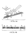
- FIG. 1A shows the chopped fiber dispenser 12 positioned at an angle ⁇ with respect to a top, or planar, surface 16t of the array of continuous fibers 16.
- the top surface 16t is oriented along the x-axis and z-axis, where the x axis is defined by a longitudinally extending length of the continuous fibers 16.
- the chopped fibers 14 are dispersed at an angle ⁇ , where the angle ⁇ is defined as the angle between the x and y axes, where the y axis is defined as being in a vertical perpendicular relationship to the x axis.
- the angle ⁇ at which the chopped fiber dispenser 12 is oriented can be varied between about 0° to about 90° to control the amount and the pattern of the chopped fibers 14 being dispensed onto the continuous fibers 16.
- the chopped fiber dispenser 12 is also movable with respect to the continuous fibers 16.
- the chopped fiber dispenser 12 can include, for example, a hydraulic system (not shown) or other suitable system can be used to enable the chopped fiber dispenser 12 to be moved to a position adjacent or above any portion of the continuous fibers 16.
- the chopped fiber dispenser 12 can be moved to different positions so that the angle of the chopped fibers 14 being deposited on the continuous fibers 16 can be varied.
- the angle ⁇ is varied by moving the chopped fiber dispenser 12 itself with respect to the top surface 16t of the continuous fibers 16 and/or by adjusting the rate of flow of chopped fibers 14 from the chopped fiber dispenser 12.
- the movement of the chopped fiber dispenser 12 with respect to the continuous fibers 16 can be controlled in any suitable manner.
- the chopped fiber dispenser 12 can be controlled by a computer (not shown) according to predetermined desired parameters so that one or more desired orientations of chopped fibers 14 are laid down on the continuous fibers 16.
- the nozzle outlet 36 of the chopped fiber dispenser 12 can be oriented along the z-axis by moving a first end 36a of the nozzle outlet 36 at an angle ⁇ with respect to a second end 36b of the nozzle outlet 36, where angle ⁇ is defined as the angle between the x and z axes.
- the angle ⁇ can be varied between about 0° to about ⁇ 90°.
- the nozzle outlet 36 can be also oriented along the z-axis by moving the nozzle outlet 36 at an angle ⁇ , where angle ⁇ is defined as the angle between the y and z axes, where the z axis is defined as a width of the array of continuous fibers 16. In this manner, the nozzle outlet 36 sweeps across the width of the array of continuous fibers 16.
- the rate of fiber deposition can be changed by adjusting (reducing/increasing) the fluid flow into the nozzle 30 during the time the nozzle 30 is directing the chopped fibers 14 to that particular area, thereby reducing/increasing the.angle of flow ( ⁇ ) and increasing/decreasing the concentration of the chopped fibers 14 on the specific area of the continuous fibers 16.
- a further level of control can be achieved by coordinating the flow of fluid into the nozzle 30 with the movement of the chopped fiber dispenser 12.
- the rate, amount and/or orientation of the chopped fiber deposition can be changed by adjusting (reducing/increasing) one or more of: 1) the rate of fluid flow into the nozzle 30; 2) the amount of fluid flow into the nozzle 30; and/or, 3) the angles of ⁇ , ⁇ , and/or ⁇ of the chopped fibers 14 being dispersed.
- This adjustment can be made during the time when the nozzle 30 is directing the chopped fibers 14 to that particular area, thereby reducing/increasing the angle of flow ( ⁇ ) and increasing/decreasing the concentration of the chopped fibers 14 on the specific area of the continuous fibers 16.
- FIG. 1B is a top plan schematic view of the top surface 16t of the continuous fibers 16 showing different orientations of chopped fibers 14.
- the chopped fibers 14 are oriented at an angle ⁇ (as shown in FIG. 1 A) , where ⁇ is defined as an angle between the x and z axes.
- the angle ⁇ can range anywhere from 0° to ⁇ 90°. For example, in FIG.
- the chopped fibers 14a are oriented at a 90° angle ⁇ ; the chopped fibers 14b are oriented at a +45° angle ⁇ ; the chopped fibers 14c are oriented at a -45° angle ⁇ ; the chopped fibers 14d are oriented at a +60° ⁇ ; and, the chopped fibers 14e are oriented at a -60° angle ⁇ .
- the deposition angle ⁇ of the chopped fibers 14 can be varied, depending on the desired parameters for the fiber reinforcement layer 17.
- the nozzle 30 need not have any particular dimensions, but in certain embodiments, the width from the first end 36a to the second end 36b of the nozzle 30 can be within the range of from about 15 to about 90 mm, and sometimes within the range of from about 25 to about 50 mm.
- the length of the nozzle 30 can be within the range of from about 40 to about 200 mm, and sometimes, within the range of from about 50 to about 90 mm.
- the flow angle ⁇ i.e., width of the dispensed chopped fibers
- a typical ratio of distance-to-width is within the range of from about 5:1 to about 1:1, and preferably within the range of from about 5:1 to about 2:1.
- the continuous fibers 16 are supplied from a suitable feeder 18.
- the feeder 18 can be any suitable device for supplying continuous fibers 16.
- the feeder 18 can comprise one or more packages of rovings.
- the feeder 18 can be a fiber forming operation where the continuous fibers 16 are supplied from bushings and are directed into the system 10.
- the continuous fibers 16 can be coated with a binder type material supplied by a suitable dispenser 24.
- the continuous fibers 16 are fed onto a collection surface 20 in a suitable manner.
- the collection surface 20 is shown as a rotating drum, but it should be understood that other collection surfaces can also be used with the system described herein.
- the collection surface can be, for example, a rotating drum, a mandrel for forming pipe, a conveyor, or a spool for a fabric material.
- the continuous fibers 16 are longitudinally supplied along an outer surface of the drum 20.
- the rotating drum 20 can be mounted along an axis A-A for rotation by any suitable means, such as by motor (not shown).
- the feeder 18 can be configured to move along the axis A-A of the collection surface 20 and to supply the continuous fibers 16 in a desired pattern on the collection surface 20.
- both the feeder 18 and the chopped fiber dispenser 12 can be configured to move axially along the axis A-A with respect to the collection surface 20.
- the chopped fibers 14 can be dispensed onto a first supply 16a of continuous fibers.
- a second supply 16b of continuous fibers is then supplied on top of the chopped fibers 14.
- the second supply 16b can be supplied at the same or a different orientation with respect to the orientation of the first supply 16a.
- FIG. 3 shows a system (not according to the present invention) for making a preform 40.
- the chopped fibers 14 are dispensed onto a mat 42.
- the mat 42 can be comprised of any suitable combination, such as randomly dispersed materials, woven materials, and/or nonwoven materials.
- the continuous fibers 16 are deposited onto the chopped fibers 14 that are covering the mat 42 so that the perform 40 is formed.
- the preform 40 can be impregnated with a suitable impregnation material from any suitable dispenser 46.
- the chopped fibers 14 can be impregnated with a suitable material such as a binder or resin material before the chopped fibers 14 are dispensed onto the continuous fibers 16.
- the continuous fibers 16 can be impregnated with a suitable material such as a binder or resin material before the continuous fibers 16 are dispensed onto the collection surface 20.
- both the chopped fibers 14 and the continuous fibers 16 can be impregnated with a suitable material.
- the impregnating material can be supplied in any suitable manner so that the fibers are substantially coated with the material.
- the material can be a thermoset resin, such as a polyester, epoxy, phenolic or polyurethane resin.
- the material can be a thermoplastic such as block copolymer of caprolactam polymer and elastomer Nyrim® resin or other suitable materials.
- FIG. 4 shows a system where a first supply of continuous fibers 16a receives a supply of chopped fibers 14. A second supply of continuous fibers 16b is deposited on the chopped fibers 14 to form a multilayer reinforcement layer 50. Thereafter, the multi-layer reinforcement layer 50 can be formed into a fabric 52 by being subjected to a needling or stitching process, generally shown by the needling apparatus 60.
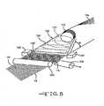
- FIG. 5 shows another system having a reinforcement dispenser 112 which is positioned to deposit chopped reinforcement fibers 14 onto an array of continuous fibers 16.
- the reinforcement dispenser 112 need not be robotized or automated, and could even be stationary with the array of continuous fibers 16 being moveable.
- a source 118 of vacuum can be positioned beneath the array of continuous fibers 16 to facilitate the deposition process.
- a compaction device 122 can be used to debulk the chopped reinforcement fibers 14.
- Reinforcement fibers 14s supplied from a source not shown, are transported to a nozzle 130 in the fiber dispenser 112 where the reinforcement fibers 14s are chopped or cut to produce the discrete length reinforcement fibers 14.
- the chopped fiber dispenser 112 has a nozzle 130 that has a nozzle chamber 134 with an outlet 136 for dispensing the chopped fibers 14.
- the nozzle chamber 134 has a tapered shape which helps to disperse the chopped fibers 14 exiting the nozzle 130 in a wider flow of chopped fibers 14 onto the continuous fibers 16. It is to be understood that, in certain embodiments, the dispersed stream of chopped fibers 14 can thus have any desired width.
- the nozzle 130 need not have any particular dimensions, but in certain embodiments, the width of the nozzle 130 can be within the range of from about 15 to about 90 mm, and sometimes within the range of from about 25 to about 50 mm.
- the length of the nozzle 130 can be within the range of from about 40 to about 200 mm, and sometimes, within the range of from about 50 to about 90 mm.
- the flow angle ⁇ i.e., width of the dispensed chopped fibers
- a typical ratio of distance-to-width is within the range of from about 5:1 to about 1:1, and preferably within the range of from about 5:1 to about 2:1.
- the reinforcement fibers 14s are wound in the nozzle 130 into a series of generally parallel loops or coils 14c.
- the coils 14c are moved down stream axially of the nozzle 130.
- the cutter 140 can be of any type capable of severing the coil 14c into discrete lengths of chopped fibers 14. Examples of cutters include heating devices and lasers.
- FIG. 5 after the coils 14c are cut by the cutter 140, they travel downwardly as discrete lengths of chopped fibers 14. The discrete lengths of fibers are laid down in a generally parallel, closely spaced fashion on the array of continuous fibers 16.
- the flow rate, the amount and/or the width of the dispersed stream of the chopped fibers 14 being dispensed from the nozzle 130 can be controlled so that the deposition of chopped fibers 14 on the continuous fibers 16 is precisely controlled, even while being deposited at a rapid rate.
- FIG. 5 shows the chopped fiber dispenser 112 positioned at an angle ⁇ with respect to the top, or planar, surface 16t of the array of continuous fibers 16.
- the top surface 16t is oriented along the x-axis and z-axis, where the x axis is defined by a longitudinally extending length of the continuous fibers 16.
- the chopped fibers 14 are dispersed at an angle ⁇ , where the angle ⁇ is defined as the angle between the x and y axes, where the y axis is defined as being in a vertical perpendicular relationship to the x axis.
- the angle ⁇ at which the chopped fiber dispenser 112 is oriented can be varied between about 0° to about 90° to control the amount and the pattern of the chopped fibers 14 being dispensed onto the continuous fibers 16.
- the chopped fiber dispenser 112 is also movable with respect to the continuous fibers 16.
- the chopped fiber dispenser 112 can be, for example, a hydraulic system (not shown) or other suitable systems can be used to enable the chopped fiber dispenser 112 to be moved to a position adjacent or above any portion of the continuous fibers 16.
- the chopped fiber dispenser 112 can be moved to different positions so that the angle of the chopped fibers 14 being deposited on the continuous fibers 16 can be varied.
- the angle ⁇ is varied by moving the chopped fiber dispenser 112 itself with respect to the top surface 16t of the continuous fibers 16 and/or by adjusting the rate of flow of chopped fibers 14 from the chopped fiber dispenser 112.
- the nozzle outlet 136 of the chopped fiber dispenser 112 can be oriented along the z-axis by adjusting a first end of the nozzle outlet 136 at an angle ⁇ with respect to a second end of the nozzle outlet 136, where angle ⁇ is defined as the angle between the x and z axes.
- the angle ⁇ can be varied between about 0° to about ⁇ 90°.
- the nozzle outlet 136 can be also oriented along the z-axis by moving the nozzle outlet 136 at an angle ⁇ , where angle ⁇ is defined as the angle between the y and z axes, where the z axis is defined as a width of the array of continuous fibers 16. In this manner, the nozzle outlet 136 sweeps across the width of the array of continuous fibers 16.
- the rate of fiber deposition can be changed by adjusting (reducing/increasing) the flow of chopped fibers 14 from the nozzle 130 during the time the nozzle 130 is directing the chopped fibers 14 to that particular area, thereby reducing/increasing the angle of flow ( ⁇ ) and increasing/decreasing the concentration of the chopped fibers 14 on the specific area of the array of continuous fibers 16.
- a further level of control can be achieved by coordinating the flow of chopped fibers 14 from the chopped fiber dispenser 112.
- the rate, amount and/or orientation of the chopped fiber deposition can be changed by adjusting (reducing/increasing) one or more of: 1) the rate of chopped fiber flow from the nozzle 130; and/or 2) the angles of ⁇ , ⁇ , and/or ⁇ of the chopped fibers 14 being dispersed.
Landscapes
- Engineering & Computer Science (AREA)
- Textile Engineering (AREA)
- Chemical & Material Sciences (AREA)
- Composite Materials (AREA)
- Mechanical Engineering (AREA)
- Nonwoven Fabrics (AREA)
- Application Of Or Painting With Fluid Materials (AREA)
- Reinforced Plastic Materials (AREA)
- Moulding By Coating Moulds (AREA)
- Preliminary Treatment Of Fibers (AREA)
- Processing And Handling Of Plastics And Other Materials For Molding In General (AREA)
- Yarns And Mechanical Finishing Of Yarns Or Ropes (AREA)
Claims (14)
- Appareil pour fabriquer une couche de renforcement fibreuse (17) possédant des fibres d'orientation transversale, l'appareil comportant un dispositif d'alimentation (18) pour assurer l'alimentation d'un ensemble de fibres continues (16 ; 16a) possédant une première orientation ; et un distributeur de fibres hachées (12) comportant une buse (30) pour distribuer des fibres hachées possédant un alignement général (14) sur l'ensemble de fibres continues selon au moins une deuxième orientation par rapport à la première orientation de l'ensemble de fibres continues, pour former la couche de renforcement fibreuse (17) ;
caractérisé en ce que
ledit distributeur de fibres hachées (12) est mobile de manière sélective par rapport audit ensemble de fibres continues (16) pour faire varier une relation de position desdites fibres hachées placées sur ledit ensemble de fibres continues, et
ladite buse (30) comporte un dispositif de guidage de fluide (38) pour guider un fluide dans la buse et commander un débit, une quantité et/ou une largeur de dispersion de flux des fibres hachées sortant de la buse en commandant le fluide entrant dans la buse (30). - Appareil selon la revendication 1, dans lequel ledit distributeur de fibres hachées est mobile par rapport audit ensemble de fibres continues qui se déplacent selon une direction longitudinale afin d'assurer la variation du mode de positionnement desdites fibres hachées sur ledit ensemble de fibres continues.
- Appareil selon la revendication 1, dans lequel le distributeur de fibres hachées est positionné selon un angle α par rapport à la surface supérieure (16t) de l'ensemble de fibres continues, ledit angle α étant défini entre un axe x défini par une longueur de prolongement longitudinal de l'ensemble de fibres continues, et un axe y, situé dans une relation perpendiculaire verticale par rapport à l'axe x, ledit distributeur de fibres hachées étant mobile pour assurer la variation dudit angle α afin de contrôler une quantité et un mode de positionnement desdites fibres hachées sur ledit ensemble de fibres continues.
- Appareil selon la revendication 1, dans lequel le dispositif d'alimentation est configuré pour assurer au moins un deuxième apport (16b) de fibres continues sur les fibres hachées.
- Appareil selon la revendication 1, comportant en outre une surface de collecte (20) configurée pour recevoir la couche de renforcement fibreuse (17).
- Appareil selon la revendication 5, dans lequel la surface de collecte est un tambour rotatif, un mandrin pour former des tubes ou une bobine pour matériau textile.
- Processus de fabrication d'une couche de renforcement fibreuse (17) possédant des fibres d'orientation. transversale, le processus comportant la mise en oeuvre d'une alimentation d'un ensemble de fibres continues (16 ; 16a) possédant une première orientation, à partir d'un premier dispositif d'alimentation (13) ; et la mise en oeuvre, au travers d'une buse (30) d'un distributeur de fibres hachées (12), d'un apport de fibres hachées (14) possédant un alignement général (14) sur l'ensemble de fibres continues selon au moins une deuxième orientation par rapport à la première orientation de l'ensemble de fibres continues, pour former la couche de renforcement fibreuse (17) ;
caractérisé en ce que
ledit distributeur de fibres hachées (12) est mobile de manière sélective par rapport audit ensemble de fibres continues pour faire varier une relation de position desdites fibres hachées placées sur ledit ensemble de fibres continues, et
ladite buse (30) comporte un dispositif de guidage de fluide (38) pour guider un fluide dans la buse et commander un débit, une quantité et/ou une largeur de dispersion de flux des fibres hachées sortant de la buse en commandant le fluide entrant dans la buse (30). - Processus selon la revendication 7, dans lequel un débit, une quantité et/ou une orientation du dépôt de fibres hachées est/sont modifié(s) en ajustant un angle selon lequel les fibres hachées sont distribuées à partir du distributeur de fibres hachées.
- Processus selon la revendication 7, comportant la mise en oeuvre d'un deuxième apport d'un ensemble de fibres continues (16b) sur les fibres hachées.
- Processus selon la revendication 7, comportant la sélection d'un mode de dépôt souhaité pour les fibres hachées distribuées sur l'ensemble de fibres continues.
- Processus selon la revendication 7, comportant l'application, au choix, au moins, sur les fibres continues ou sur les fibres hachées, d'un matériau liant.
- Processus selon la revendication 7, comportant le guidage de la couche de renforcement fibreuse (17) vers une surface de collecte (20).
- Processus selon la revendication 12, dans lequel la surface de collecte est un tambour rotatif, un mandrin permettant de former des tubes, an système de convoyeur ou une bobine pour matériau textile.
- Processus selon la revendication 12, comportant le déplacement du dispositif d'alimentation (18) par rapport à la surface de collecte.
Priority Applications (1)
| Application Number | Priority Date | Filing Date | Title |
|---|---|---|---|
| PL07836959T PL2073975T3 (pl) | 2006-08-25 | 2007-08-16 | System do formowania warstw wzmacniających posiadających włókna zorientowane poprzecznie |
Applications Claiming Priority (2)
| Application Number | Priority Date | Filing Date | Title |
|---|---|---|---|
| US11/510,221 US8028736B2 (en) | 2006-08-25 | 2006-08-25 | System for forming reinforcement layers having cross-directionally oriented fibers |
| PCT/US2007/018217 WO2008027206A2 (fr) | 2006-08-25 | 2007-08-16 | Système de formation de couches de renforcement présentant des fibres orientées transversalement |
Publications (2)
| Publication Number | Publication Date |
|---|---|
| EP2073975A2 EP2073975A2 (fr) | 2009-07-01 |
| EP2073975B1 true EP2073975B1 (fr) | 2013-03-13 |
Family
ID=39025918
Family Applications (1)
| Application Number | Title | Priority Date | Filing Date |
|---|---|---|---|
| EP07836959A Not-in-force EP2073975B1 (fr) | 2006-08-25 | 2007-08-16 | Système de formation de couches de renforcement présentant des fibres orientées transversalement |
Country Status (8)
| Country | Link |
|---|---|
| US (1) | US8028736B2 (fr) |
| EP (1) | EP2073975B1 (fr) |
| DK (1) | DK2073975T3 (fr) |
| EA (1) | EA017245B1 (fr) |
| ES (1) | ES2408229T3 (fr) |
| PL (1) | PL2073975T3 (fr) |
| PT (1) | PT2073975E (fr) |
| WO (1) | WO2008027206A2 (fr) |
Families Citing this family (17)
| Publication number | Priority date | Publication date | Assignee | Title |
|---|---|---|---|---|
| US8028736B2 (en) | 2006-08-25 | 2011-10-04 | Ocv Intellectual Capital, Llc | System for forming reinforcement layers having cross-directionally oriented fibers |
| NL1036355C2 (en) * | 2008-12-22 | 2009-10-27 | Willem Frans Van Der Mast | A method for supplying reinforcement fibers to an object. |
| US8992711B2 (en) * | 2010-09-21 | 2015-03-31 | The Boeing Company | Method and apparatus for making fiber reinforced composite tubes |
| JP5808420B2 (ja) | 2010-12-02 | 2015-11-10 | トウホウ テナックス ユーロップ ゲゼルシャフト ミット ベシュレンクテル ハフツングToho Tenax Europe GmbH | 一方向繊維テープを有し、強化用繊維束の繊維プリフォーム及び複合材料部材 |
| AT511349B1 (de) * | 2011-09-21 | 2012-11-15 | Kapsch Group Beteiligungs Gmbh | Faserhalbzeug, faser-verbundwerkstoff und verfahren zu deren herstellung |
| WO2013071448A1 (fr) | 2011-11-16 | 2013-05-23 | Flexpipe Systems Inc. | Raccordement pour canalisation thermoplastique, ensemble et procédé |
| DK2780159T3 (en) | 2011-11-16 | 2019-04-08 | Shawcor Ltd | Flexible reinforced pipeline and reinforcement tape |
| WO2013120201A1 (fr) | 2012-02-17 | 2013-08-22 | 8193053 Canada Ltd. | Tuyau, raccord de tuyau et système de canalisation |
| DE102012203388A1 (de) * | 2012-03-05 | 2013-09-05 | Voith Patent Gmbh | Querablegen von Fasern |
| WO2014062539A1 (fr) * | 2012-10-16 | 2014-04-24 | Ocv Intellectual Capital, Llc | Revêtement intérieur permettant de renforcer une conduite et son procédé de fabrication |
| EP3152044A4 (fr) | 2014-06-04 | 2017-12-20 | Bright Lite Structures LlC | Structure composite présentant une absorption d'énergie et/ou comprenant une surface sans défaut |
| JP6602391B2 (ja) * | 2015-04-03 | 2019-11-06 | ブライト ライト ストラクチャーズ エルエルシー | 繊維を制御可能に切断するための装置及び関連する方法 |
| US10160004B2 (en) | 2015-07-07 | 2018-12-25 | Palo Alto Research Center Incorporated | Creating aligned and oriented fiber reinforced polymer composites |
| US10625486B2 (en) | 2016-06-20 | 2020-04-21 | Johns Manville | Methods of producing thermoplastic composites using fabric-based thermoplastic prepregs |
| KR102253104B1 (ko) * | 2017-05-19 | 2021-05-14 | (주)엘지하우시스 | 섬유강화 복합재 및 그 제조 방법 |
| CN109228399A (zh) * | 2018-10-16 | 2019-01-18 | 深圳市创旭腾新材料科技有限公司 | 一种热固性复合材料短切纤维与连续纤维的一体成型方法 |
| WO2020106678A1 (fr) | 2018-11-19 | 2020-05-28 | Bright Lite Structures Llc | Composites à faible dégagement de chaleur et à haute résistance faisant référence à des applications associées |
Family Cites Families (70)
| Publication number | Priority date | Publication date | Assignee | Title |
|---|---|---|---|---|
| US2215150A (en) | 1936-12-28 | 1940-09-17 | Hannen Clemens | Process for treating mineral fibrous substances, such as glass wool, slag wool, or the like |
| DE929123C (de) | 1953-04-30 | 1955-06-20 | Heinrich Buddecke | Wickelkopf fuer die Herstellung von aus laenglich schraubenlinienfoermigen Windungen bestehenden Garnlagen fuer Garnpackungen |
| US2892307A (en) | 1955-11-17 | 1959-06-30 | Westinghouse Electric Corp | "hot streak" ignition arrangement for afterburner fuel control system |
| US2954817A (en) | 1957-10-11 | 1960-10-04 | St Regis Paper Co | Apparatus and method for forming and applying strand reinforcement and product produced thereby |
| US3170197A (en) | 1961-01-12 | 1965-02-23 | Ivan G Brenner | Apparatus for producing a fibrous glass preform |
| US3377233A (en) | 1964-04-08 | 1968-04-09 | John G. Jackson | Coated glass thread |
| DE1560007A1 (de) | 1966-05-27 | 1969-07-17 | Heinrich Buddecke | Wickelkopf fuer die Herstellung eines Garnbandes das aus quer liegenden Garnwindungen besteht |
| FR1584056A (fr) * | 1968-07-29 | 1969-12-12 | ||
| US3728195A (en) | 1969-02-10 | 1973-04-17 | Deering Milliken Res Corp | Apparatus for the production of non-woven net fabrics |
| US3728189A (en) | 1969-06-06 | 1973-04-17 | Johns Manville | Method and apparatus for fabricating a plurality of filaments into a helix |
| US3831879A (en) | 1970-03-11 | 1974-08-27 | Us Navy | Wire dispenser |
| US3719540A (en) | 1970-05-04 | 1973-03-06 | Hercules Inc | Preparation of transversely fibrillated film |
| US3864443A (en) | 1970-05-27 | 1975-02-04 | Arthur Hopkins | Method of making light-weight concrete aggregate |
| US3892307A (en) * | 1972-09-05 | 1975-07-01 | American Air Filter Co | Conveyor having adjustable flights |
| JPS4986638A (fr) | 1972-12-25 | 1974-08-20 | ||
| JPS5040185B2 (fr) * | 1973-01-18 | 1975-12-22 | ||
| US4018964A (en) | 1973-07-27 | 1977-04-19 | Nippon Asbestos Company, Ltd. | Method for preparing glassy fiber having protuberances studded on the surface useful for reinforcement and resulting product |
| US3977069A (en) | 1974-12-18 | 1976-08-31 | Brunswick Corporation | Process and apparatus for production of precision cut lengths of metal wires and fibers |
| US4001935A (en) | 1975-06-12 | 1977-01-11 | Binks Manufacturing Company | Roving cutter |
| NL7802576A (nl) | 1977-05-13 | 1978-11-15 | Neumuenster Masch App | Werkwijze en inrichting voor het behandelen van vezelbanden. |
| JPS5431533A (en) | 1977-08-15 | 1979-03-08 | Hitachi Ltd | High voltage thyristor device |
| CA1110817A (fr) * | 1978-02-23 | 1981-10-20 | Atlantic Bridge Company Limited | Articles en plastique arme de fibres, et methode et dispositif de fabrication connexes |
| US4178670A (en) | 1978-06-22 | 1979-12-18 | Crystal Systems, Inc. | Process of forming a wire pack |
| US4352769A (en) | 1980-05-27 | 1982-10-05 | Victor United, Inc. | Method for simultaneously molding a plurality of products |
| JPS5913423A (ja) | 1982-07-14 | 1984-01-24 | Matsushita Electric Ind Co Ltd | ゲ−ト・タ−ン・オフ・サイリスタ |
| US4519281A (en) | 1983-03-07 | 1985-05-28 | Eastman Kodak Company | Package wind cutter |
| GB2158471B (en) | 1984-05-04 | 1988-03-16 | Budd Co | Fiberous armor material |
| US4750960A (en) | 1984-09-10 | 1988-06-14 | Rensselaer Polytechnic Institute | Robotic winding system and method |
| FR2581631B1 (fr) | 1985-05-07 | 1987-07-10 | Superba Sa | Dispositif a vis sans fin pour former des boucles plates de fils textiles |
| US4630515A (en) | 1985-10-15 | 1986-12-23 | Eastman Kodak Company | Apparatus for cutting continuous strand |
| US4780432A (en) | 1986-09-02 | 1988-10-25 | United Technologies Corporation | Controlled fiber distribution technique for glass matrix composites |
| US4752313A (en) | 1986-12-16 | 1988-06-21 | Corning Glass Works | Pultrusion process for fiber-reinforced composites |
| US4854990A (en) | 1987-04-13 | 1989-08-08 | David Constant V | Method for fabricating and inserting reinforcing spikes in a 3-D reinforced structure |
| US5192390A (en) | 1987-11-13 | 1993-03-09 | Bridgestone/Firestone Inc. | Mandrel means |
| JP2547238B2 (ja) | 1988-03-29 | 1996-10-23 | 株式会社日本触媒 | 繊維強化樹脂成形材料の製造方法 |
| US4921518A (en) | 1988-12-23 | 1990-05-01 | Corning Incorporated | Method of making short fiber reinforced glass and glass-ceramic matrix composites |
| US4973440A (en) | 1989-03-15 | 1990-11-27 | Nippon Shokubai Kagaku Kogyo Co., Ltd. | Method for production of fiber-reinforced thermosetting resin molding material |
| US5432000A (en) | 1989-03-20 | 1995-07-11 | Weyerhaeuser Company | Binder coated discontinuous fibers with adhered particulate materials |
| US5020403A (en) | 1989-06-20 | 1991-06-04 | Angelo Joseph J D | Web feeding, cutting and dispensing machine |
| SU1694724A1 (ru) | 1989-08-02 | 1991-11-30 | Предприятие П/Я А-7317 | Устройство дл разрезани нитей на отрезки |
| US4944446A (en) | 1989-11-02 | 1990-07-31 | Micron Technology, Inc. | Automatic preform dispenser |
| US5229052A (en) | 1990-02-23 | 1993-07-20 | Wellman Machinery Of Michigan, Inc. | Apparatus and method for applying multiple type fibers to a foraminous surface |
| US5084035A (en) | 1990-03-27 | 1992-01-28 | The Kendall Company | Drainage device |
| JPH0452106A (ja) | 1990-06-20 | 1992-02-20 | Japan Steel Works Ltd:The | 繊維強化プラスチック成形品の製造方法 |
| CA2057201C (fr) * | 1990-12-19 | 1998-05-19 | Vernon M. Benson | Machine a axes multiples servant a mettre en place la fibre |
| US5158631A (en) | 1991-01-15 | 1992-10-27 | United Technologies Corporation | Method of manufacturing a dog-leg shaped ply of composite material and the tool used in carrying out the method |
| US5204033A (en) | 1991-10-21 | 1993-04-20 | Brunswick Corporation | Method of fabricating a preform in a resin transfer molding process |
| US5463919A (en) | 1991-11-02 | 1995-11-07 | Zortech International Limited | Apparatus for cutting wound coils |
| US5262106A (en) | 1992-02-06 | 1993-11-16 | The United States Of America As Represented By The United States Department Of Energy | Anisotropic fiber alignment in composite structures |
| RU2113419C1 (ru) | 1993-07-06 | 1998-06-20 | Апликатор Систем АБ | Устройство, предназначенное для подачи армирующих волокон при производстве термоотверждаемой пластмассовой продукции |
| EP0634265A1 (fr) | 1993-07-14 | 1995-01-18 | General Electric Company | Procédé de thermoformage |
| JPH07107205A (ja) | 1993-10-05 | 1995-04-21 | Matsushita Electric Ind Co Ltd | 画像通信端末装置 |
| US5484641A (en) | 1993-11-01 | 1996-01-16 | Rotter; Martin J. | Process for fixing plastic reinforcing pins into non-woven filamentary material and product produced by the process |
| JPH07215587A (ja) | 1994-01-26 | 1995-08-15 | Furukawa Electric Co Ltd:The | 線条体の切り分け装置 |
| US5806387A (en) | 1995-04-10 | 1998-09-15 | N.V. Owens-Corning S.A. | Method for dispensing resinated reinforcement fibers |
| JPH11507104A (ja) | 1995-04-10 | 1999-06-22 | ナムローゼ フェンノートシャップ オウェンス コーニング ソシエテ アノニム | 強化繊維の分与方法 |
| US5826812A (en) | 1997-01-08 | 1998-10-27 | Belmont Textile Machinery Co., Inc. | Coiler apparatus and method |
| FR2760596B1 (fr) | 1997-03-14 | 1999-04-02 | Speed France | Fil de coupe composite pour debroussailleuses et taille-bordures |
| FR2761380B1 (fr) * | 1997-03-28 | 1999-07-02 | Europ Propulsion | Procede et machine pour la realisation de nappes fibreuses multiaxiales |
| US6949289B1 (en) | 1998-03-03 | 2005-09-27 | Ppg Industries Ohio, Inc. | Impregnated glass fiber strands and products including the same |
| US6029897A (en) | 1998-03-19 | 2000-02-29 | N.V. Owens-Corning S.A. | Method of dispensing chopped reinforcement strand using a vortex nozzle |
| US6038949A (en) | 1998-09-14 | 2000-03-21 | Nv Owens-Corning S.A. | Method for dispensing reinforcement fibers |
| US6325605B1 (en) | 1998-11-02 | 2001-12-04 | Owens Corning Canada Inc. | Apparatus to control the dispersion and deposition of chopped fibrous strands |
| US6182332B1 (en) | 1999-07-30 | 2001-02-06 | Owens Corning Composites Sprl | Method of forming discrete length fibers |
| FR2797892B1 (fr) | 1999-08-27 | 2002-08-30 | Vetrotex France Sa | Procede et dispositif de fabrication de plaques composites |
| US6615875B2 (en) | 2000-08-30 | 2003-09-09 | Owens Corning Composites Sprl. | Liner for reinforcing a pipe and method of making the same |
| US7514135B2 (en) | 2001-06-14 | 2009-04-07 | Omniglass Ltd. | Pultruded part reinforced by longitudinal and transverse fibers and a method of manufacturing thereof |
| US6527211B1 (en) | 2001-08-07 | 2003-03-04 | Masco Corporation | Blade and spring fiber chopper |
| US7353853B2 (en) * | 2005-05-03 | 2008-04-08 | Cincinnati Machine, Llc | Fiber placement machine |
| US8028736B2 (en) | 2006-08-25 | 2011-10-04 | Ocv Intellectual Capital, Llc | System for forming reinforcement layers having cross-directionally oriented fibers |
-
2006
- 2006-08-25 US US11/510,221 patent/US8028736B2/en not_active Expired - Fee Related
-
2007
- 2007-08-16 PL PL07836959T patent/PL2073975T3/pl unknown
- 2007-08-16 EA EA200970225A patent/EA017245B1/ru not_active IP Right Cessation
- 2007-08-16 EP EP07836959A patent/EP2073975B1/fr not_active Not-in-force
- 2007-08-16 ES ES07836959T patent/ES2408229T3/es active Active
- 2007-08-16 DK DK07836959.2T patent/DK2073975T3/da active
- 2007-08-16 PT PT78369592T patent/PT2073975E/pt unknown
- 2007-08-16 WO PCT/US2007/018217 patent/WO2008027206A2/fr not_active Ceased
Also Published As
| Publication number | Publication date |
|---|---|
| PL2073975T3 (pl) | 2013-08-30 |
| EP2073975A2 (fr) | 2009-07-01 |
| EA017245B1 (ru) | 2012-11-30 |
| WO2008027206A2 (fr) | 2008-03-06 |
| EA200970225A1 (ru) | 2009-08-28 |
| US8028736B2 (en) | 2011-10-04 |
| ES2408229T3 (es) | 2013-06-19 |
| PT2073975E (pt) | 2013-05-06 |
| DK2073975T3 (da) | 2013-06-17 |
| WO2008027206A3 (fr) | 2008-04-24 |
| US20080047657A1 (en) | 2008-02-28 |
Similar Documents
| Publication | Publication Date | Title |
|---|---|---|
| EP2073975A2 (fr) | Système de formation de couches de renforcement présentant des fibres orientées transversalement | |
| CN104768725B (zh) | 用于制造纤维型坯的方法 | |
| CA2680470C (fr) | Procede et dispositif de fabrication d'une preforme pour une structure en materiau renforce par des fibres adaptee a des flux de forces | |
| DK2578384T3 (en) | The fiber routing device and use thereof | |
| CA2680457A1 (fr) | Dispositif d'ecartement servant a ecarter des faisceaux de filaments de fibres, et procede d'ecartement pouvant etre mis en oeuvre au moyen de ce dispositif d'ecartement | |
| EP0907475B1 (fr) | Procede de distribution de fibres de renforcement resineuses | |
| JPH02196637A (ja) | ガラス繊維補強熱可塑性シート | |
| US5819614A (en) | Method for dispensing reinforcement fibers | |
| CA1130713A (fr) | Corps composite haute resistance fait de resine, de fibres enroulees en helice et de fibres continues spiralees, et methode de faconnage connexe | |
| EP1077805B1 (fr) | Procede de distribution de fils de renfort coupes utilisant une buse tourbillonnaire | |
| CA1121705A (fr) | Composite haute resistance fait resine, fibres helicoidales et fibres courtes, et methode de fabrication connexe | |
| EP1144288B1 (fr) | Procede de distribution de fibres de renfort | |
| RU2632300C2 (ru) | Укладочное устройство для управляемой укладки пучков упрочняющих волокон | |
| US20050118390A1 (en) | Continuous strand mats, methods of producing continuous strand mats, and systems for producing continuous strand mats | |
| MXPA00009148A (en) | Method of dispensing chopped reinforcement strand using a vortex nozzle |
Legal Events
| Date | Code | Title | Description |
|---|---|---|---|
| PUAI | Public reference made under article 153(3) epc to a published international application that has entered the european phase |
Free format text: ORIGINAL CODE: 0009012 |
|
| 17P | Request for examination filed |
Effective date: 20090325 |
|
| AK | Designated contracting states |
Kind code of ref document: A2 Designated state(s): AT BE BG CH CY CZ DE DK EE ES FI FR GB GR HU IE IS IT LI LT LU LV MC MT NL PL PT RO SE SI SK TR |
|
| AX | Request for extension of the european patent |
Extension state: AL BA HR MK RS |
|
| RIN1 | Information on inventor provided before grant (corrected) |
Inventor name: JANDER, MICHAEL |
|
| 17Q | First examination report despatched |
Effective date: 20090720 |
|
| DAX | Request for extension of the european patent (deleted) | ||
| GRAP | Despatch of communication of intention to grant a patent |
Free format text: ORIGINAL CODE: EPIDOSNIGR1 |
|
| GRAS | Grant fee paid |
Free format text: ORIGINAL CODE: EPIDOSNIGR3 |
|
| GRAA | (expected) grant |
Free format text: ORIGINAL CODE: 0009210 |
|
| AK | Designated contracting states |
Kind code of ref document: B1 Designated state(s): AT BE BG CH CY CZ DE DK EE ES FI FR GB GR HU IE IS IT LI LT LU LV MC MT NL PL PT RO SE SI SK TR |
|
| REG | Reference to a national code |
Ref country code: GB Ref legal event code: FG4D |
|
| REG | Reference to a national code |
Ref country code: AT Ref legal event code: REF Ref document number: 600536 Country of ref document: AT Kind code of ref document: T Effective date: 20130315 Ref country code: CH Ref legal event code: EP |
|
| REG | Reference to a national code |
Ref country code: IE Ref legal event code: FG4D |
|
| REG | Reference to a national code |
Ref country code: PT Ref legal event code: SC4A Free format text: AVAILABILITY OF NATIONAL TRANSLATION Effective date: 20130424 |
|
| REG | Reference to a national code |
Ref country code: DE Ref legal event code: R096 Ref document number: 602007029104 Country of ref document: DE Effective date: 20130508 |
|
| REG | Reference to a national code |
Ref country code: DK Ref legal event code: T3 |
|
| REG | Reference to a national code |
Ref country code: ES Ref legal event code: FG2A Ref document number: 2408229 Country of ref document: ES Kind code of ref document: T3 Effective date: 20130619 |
|
| REG | Reference to a national code |
Ref country code: SE Ref legal event code: TRGR |
|
| PG25 | Lapsed in a contracting state [announced via postgrant information from national office to epo] |
Ref country code: LT Free format text: LAPSE BECAUSE OF FAILURE TO SUBMIT A TRANSLATION OF THE DESCRIPTION OR TO PAY THE FEE WITHIN THE PRESCRIBED TIME-LIMIT Effective date: 20130313 Ref country code: BG Free format text: LAPSE BECAUSE OF FAILURE TO SUBMIT A TRANSLATION OF THE DESCRIPTION OR TO PAY THE FEE WITHIN THE PRESCRIBED TIME-LIMIT Effective date: 20130613 |
|
| REG | Reference to a national code |
Ref country code: NL Ref legal event code: T3 |
|
| REG | Reference to a national code |
Ref country code: LT Ref legal event code: MG4D |
|
| PG25 | Lapsed in a contracting state [announced via postgrant information from national office to epo] |
Ref country code: SI Free format text: LAPSE BECAUSE OF FAILURE TO SUBMIT A TRANSLATION OF THE DESCRIPTION OR TO PAY THE FEE WITHIN THE PRESCRIBED TIME-LIMIT Effective date: 20130313 Ref country code: GR Free format text: LAPSE BECAUSE OF FAILURE TO SUBMIT A TRANSLATION OF THE DESCRIPTION OR TO PAY THE FEE WITHIN THE PRESCRIBED TIME-LIMIT Effective date: 20130614 Ref country code: LV Free format text: LAPSE BECAUSE OF FAILURE TO SUBMIT A TRANSLATION OF THE DESCRIPTION OR TO PAY THE FEE WITHIN THE PRESCRIBED TIME-LIMIT Effective date: 20130313 |
|
| REG | Reference to a national code |
Ref country code: PL Ref legal event code: T3 |
|
| PG25 | Lapsed in a contracting state [announced via postgrant information from national office to epo] |
Ref country code: EE Free format text: LAPSE BECAUSE OF FAILURE TO SUBMIT A TRANSLATION OF THE DESCRIPTION OR TO PAY THE FEE WITHIN THE PRESCRIBED TIME-LIMIT Effective date: 20130313 Ref country code: IS Free format text: LAPSE BECAUSE OF FAILURE TO SUBMIT A TRANSLATION OF THE DESCRIPTION OR TO PAY THE FEE WITHIN THE PRESCRIBED TIME-LIMIT Effective date: 20130713 Ref country code: SK Free format text: LAPSE BECAUSE OF FAILURE TO SUBMIT A TRANSLATION OF THE DESCRIPTION OR TO PAY THE FEE WITHIN THE PRESCRIBED TIME-LIMIT Effective date: 20130313 Ref country code: RO Free format text: LAPSE BECAUSE OF FAILURE TO SUBMIT A TRANSLATION OF THE DESCRIPTION OR TO PAY THE FEE WITHIN THE PRESCRIBED TIME-LIMIT Effective date: 20130313 |
|
| PGFP | Annual fee paid to national office [announced via postgrant information from national office to epo] |
Ref country code: FI Payment date: 20130813 Year of fee payment: 7 Ref country code: SE Payment date: 20130821 Year of fee payment: 7 Ref country code: AT Payment date: 20130813 Year of fee payment: 7 Ref country code: PT Payment date: 20130424 Year of fee payment: 7 |
|
| PG25 | Lapsed in a contracting state [announced via postgrant information from national office to epo] |
Ref country code: CY Free format text: LAPSE BECAUSE OF FAILURE TO SUBMIT A TRANSLATION OF THE DESCRIPTION OR TO PAY THE FEE WITHIN THE PRESCRIBED TIME-LIMIT Effective date: 20130313 |
|
| PLBE | No opposition filed within time limit |
Free format text: ORIGINAL CODE: 0009261 |
|
| STAA | Information on the status of an ep patent application or granted ep patent |
Free format text: STATUS: NO OPPOSITION FILED WITHIN TIME LIMIT |
|
| 26N | No opposition filed |
Effective date: 20131216 |
|
| REG | Reference to a national code |
Ref country code: DE Ref legal event code: R097 Ref document number: 602007029104 Country of ref document: DE Effective date: 20131216 |
|
| REG | Reference to a national code |
Ref country code: CH Ref legal event code: PL |
|
| PG25 | Lapsed in a contracting state [announced via postgrant information from national office to epo] |
Ref country code: LI Free format text: LAPSE BECAUSE OF NON-PAYMENT OF DUE FEES Effective date: 20130831 Ref country code: CH Free format text: LAPSE BECAUSE OF NON-PAYMENT OF DUE FEES Effective date: 20130831 Ref country code: MC Free format text: LAPSE BECAUSE OF FAILURE TO SUBMIT A TRANSLATION OF THE DESCRIPTION OR TO PAY THE FEE WITHIN THE PRESCRIBED TIME-LIMIT Effective date: 20130313 |
|
| REG | Reference to a national code |
Ref country code: IE Ref legal event code: MM4A |
|
| PG25 | Lapsed in a contracting state [announced via postgrant information from national office to epo] |
Ref country code: IE Free format text: LAPSE BECAUSE OF NON-PAYMENT OF DUE FEES Effective date: 20130816 |
|
| REG | Reference to a national code |
Ref country code: PT Ref legal event code: MM4A Free format text: LAPSE DUE TO NON-PAYMENT OF FEES Effective date: 20150216 |
|
| REG | Reference to a national code |
Ref country code: SE Ref legal event code: EUG |
|
| REG | Reference to a national code |
Ref country code: AT Ref legal event code: MM01 Ref document number: 600536 Country of ref document: AT Kind code of ref document: T Effective date: 20140816 |
|
| PG25 | Lapsed in a contracting state [announced via postgrant information from national office to epo] |
Ref country code: PT Free format text: LAPSE BECAUSE OF NON-PAYMENT OF DUE FEES Effective date: 20150216 Ref country code: FI Free format text: LAPSE BECAUSE OF NON-PAYMENT OF DUE FEES Effective date: 20140816 |
|
| PG25 | Lapsed in a contracting state [announced via postgrant information from national office to epo] |
Ref country code: SE Free format text: LAPSE BECAUSE OF NON-PAYMENT OF DUE FEES Effective date: 20140817 Ref country code: AT Free format text: LAPSE BECAUSE OF NON-PAYMENT OF DUE FEES Effective date: 20140816 |
|
| PG25 | Lapsed in a contracting state [announced via postgrant information from national office to epo] |
Ref country code: MT Free format text: LAPSE BECAUSE OF FAILURE TO SUBMIT A TRANSLATION OF THE DESCRIPTION OR TO PAY THE FEE WITHIN THE PRESCRIBED TIME-LIMIT Effective date: 20130313 |
|
| PG25 | Lapsed in a contracting state [announced via postgrant information from national office to epo] |
Ref country code: LU Free format text: LAPSE BECAUSE OF NON-PAYMENT OF DUE FEES Effective date: 20130816 Ref country code: HU Free format text: LAPSE BECAUSE OF FAILURE TO SUBMIT A TRANSLATION OF THE DESCRIPTION OR TO PAY THE FEE WITHIN THE PRESCRIBED TIME-LIMIT; INVALID AB INITIO Effective date: 20070816 |
|
| REG | Reference to a national code |
Ref country code: FR Ref legal event code: PLFP Year of fee payment: 10 |
|
| REG | Reference to a national code |
Ref country code: FR Ref legal event code: PLFP Year of fee payment: 11 |
|
| PGFP | Annual fee paid to national office [announced via postgrant information from national office to epo] |
Ref country code: NL Payment date: 20170826 Year of fee payment: 11 |
|
| PGFP | Annual fee paid to national office [announced via postgrant information from national office to epo] |
Ref country code: FR Payment date: 20170825 Year of fee payment: 11 Ref country code: ES Payment date: 20170901 Year of fee payment: 11 Ref country code: IT Payment date: 20170823 Year of fee payment: 11 Ref country code: CZ Payment date: 20170803 Year of fee payment: 11 Ref country code: DE Payment date: 20170829 Year of fee payment: 11 Ref country code: GB Payment date: 20170829 Year of fee payment: 11 |
|
| PGFP | Annual fee paid to national office [announced via postgrant information from national office to epo] |
Ref country code: PL Payment date: 20170802 Year of fee payment: 11 Ref country code: BE Payment date: 20170828 Year of fee payment: 11 Ref country code: DK Payment date: 20170825 Year of fee payment: 11 Ref country code: TR Payment date: 20170802 Year of fee payment: 11 |
|
| REG | Reference to a national code |
Ref country code: DE Ref legal event code: R119 Ref document number: 602007029104 Country of ref document: DE |
|
| REG | Reference to a national code |
Ref country code: DK Ref legal event code: EBP Effective date: 20180831 |
|
| REG | Reference to a national code |
Ref country code: NL Ref legal event code: MM Effective date: 20180901 |
|
| GBPC | Gb: european patent ceased through non-payment of renewal fee |
Effective date: 20180816 |
|
| PG25 | Lapsed in a contracting state [announced via postgrant information from national office to epo] |
Ref country code: CZ Free format text: LAPSE BECAUSE OF NON-PAYMENT OF DUE FEES Effective date: 20180816 |
|
| REG | Reference to a national code |
Ref country code: BE Ref legal event code: MM Effective date: 20180831 |
|
| PG25 | Lapsed in a contracting state [announced via postgrant information from national office to epo] |
Ref country code: NL Free format text: LAPSE BECAUSE OF NON-PAYMENT OF DUE FEES Effective date: 20180901 |
|
| PG25 | Lapsed in a contracting state [announced via postgrant information from national office to epo] |
Ref country code: IT Free format text: LAPSE BECAUSE OF NON-PAYMENT OF DUE FEES Effective date: 20180816 Ref country code: DK Free format text: LAPSE BECAUSE OF NON-PAYMENT OF DUE FEES Effective date: 20180831 Ref country code: DE Free format text: LAPSE BECAUSE OF NON-PAYMENT OF DUE FEES Effective date: 20190301 |
|
| PG25 | Lapsed in a contracting state [announced via postgrant information from national office to epo] |
Ref country code: FR Free format text: LAPSE BECAUSE OF NON-PAYMENT OF DUE FEES Effective date: 20180831 Ref country code: BE Free format text: LAPSE BECAUSE OF NON-PAYMENT OF DUE FEES Effective date: 20180831 |
|
| REG | Reference to a national code |
Ref country code: ES Ref legal event code: FD2A Effective date: 20190918 |
|
| PG25 | Lapsed in a contracting state [announced via postgrant information from national office to epo] |
Ref country code: GB Free format text: LAPSE BECAUSE OF NON-PAYMENT OF DUE FEES Effective date: 20180816 Ref country code: ES Free format text: LAPSE BECAUSE OF NON-PAYMENT OF DUE FEES Effective date: 20180817 |
|
| PG25 | Lapsed in a contracting state [announced via postgrant information from national office to epo] |
Ref country code: PL Free format text: LAPSE BECAUSE OF NON-PAYMENT OF DUE FEES Effective date: 20180816 |
|
| PG25 | Lapsed in a contracting state [announced via postgrant information from national office to epo] |
Ref country code: TR Free format text: LAPSE BECAUSE OF NON-PAYMENT OF DUE FEES Effective date: 20180816 |