EP2074028B1 - Optimierte abtauregelungsanordnung und verfahren für parallel angeordneten frischluftauslässen von klimaanlagen - Google Patents
Optimierte abtauregelungsanordnung und verfahren für parallel angeordneten frischluftauslässen von klimaanlagen Download PDFInfo
- Publication number
- EP2074028B1 EP2074028B1 EP20070818969 EP07818969A EP2074028B1 EP 2074028 B1 EP2074028 B1 EP 2074028B1 EP 20070818969 EP20070818969 EP 20070818969 EP 07818969 A EP07818969 A EP 07818969A EP 2074028 B1 EP2074028 B1 EP 2074028B1
- Authority
- EP
- European Patent Office
- Prior art keywords
- air
- pipeline
- temperature
- turbine
- fresh air
- Prior art date
- Legal status (The legal status is an assumption and is not a legal conclusion. Google has not performed a legal analysis and makes no representation as to the accuracy of the status listed.)
- Not-in-force
Links
- 238000000034 method Methods 0.000 title claims abstract description 129
- 238000010257 thawing Methods 0.000 title 1
- 230000008569 process Effects 0.000 claims abstract description 99
- 230000001105 regulatory effect Effects 0.000 claims abstract description 63
- 238000001816 cooling Methods 0.000 claims description 33
- 238000010438 heat treatment Methods 0.000 claims description 10
- FGUUSXIOTUKUDN-IBGZPJMESA-N C1(=CC=CC=C1)N1C2=C(NC([C@H](C1)NC=1OC(=NN=1)C1=CC=CC=C1)=O)C=CC=C2 Chemical compound C1(=CC=CC=C1)N1C2=C(NC([C@H](C1)NC=1OC(=NN=1)C1=CC=CC=C1)=O)C=CC=C2 FGUUSXIOTUKUDN-IBGZPJMESA-N 0.000 claims description 6
- 230000035508 accumulation Effects 0.000 claims description 5
- 238000009825 accumulation Methods 0.000 claims description 5
- GNFTZDOKVXKIBK-UHFFFAOYSA-N 3-(2-methoxyethoxy)benzohydrazide Chemical compound COCCOC1=CC=CC(C(=O)NN)=C1 GNFTZDOKVXKIBK-UHFFFAOYSA-N 0.000 claims description 4
- 239000003570 air Substances 0.000 description 310
- 238000004378 air conditioning Methods 0.000 description 10
- 239000002245 particle Substances 0.000 description 7
- 230000010355 oscillation Effects 0.000 description 4
- 239000012080 ambient air Substances 0.000 description 3
- XLYOFNOQVPJJNP-UHFFFAOYSA-N water Substances O XLYOFNOQVPJJNP-UHFFFAOYSA-N 0.000 description 3
- 230000015572 biosynthetic process Effects 0.000 description 2
- 230000008859 change Effects 0.000 description 2
- 238000010276 construction Methods 0.000 description 2
- 230000009021 linear effect Effects 0.000 description 2
- 235000007575 Calluna vulgaris Nutrition 0.000 description 1
- YTAHJIFKAKIKAV-XNMGPUDCSA-N [(1R)-3-morpholin-4-yl-1-phenylpropyl] N-[(3S)-2-oxo-5-phenyl-1,3-dihydro-1,4-benzodiazepin-3-yl]carbamate Chemical compound O=C1[C@H](N=C(C2=C(N1)C=CC=C2)C1=CC=CC=C1)NC(O[C@H](CCN1CCOCC1)C1=CC=CC=C1)=O YTAHJIFKAKIKAV-XNMGPUDCSA-N 0.000 description 1
- 230000008901 benefit Effects 0.000 description 1
- 230000015556 catabolic process Effects 0.000 description 1
- 239000013078 crystal Substances 0.000 description 1
- 125000004122 cyclic group Chemical group 0.000 description 1
- 230000006837 decompression Effects 0.000 description 1
- 230000000694 effects Effects 0.000 description 1
- 238000007710 freezing Methods 0.000 description 1
- 230000008014 freezing Effects 0.000 description 1
- 239000007789 gas Substances 0.000 description 1
- 239000000203 mixture Substances 0.000 description 1
- 239000002918 waste heat Substances 0.000 description 1
Images


Classifications
-
- B—PERFORMING OPERATIONS; TRANSPORTING
- B64—AIRCRAFT; AVIATION; COSMONAUTICS
- B64D—EQUIPMENT FOR FITTING IN OR TO AIRCRAFT; FLIGHT SUITS; PARACHUTES; ARRANGEMENT OR MOUNTING OF POWER PLANTS OR PROPULSION TRANSMISSIONS IN AIRCRAFT
- B64D13/00—Arrangements or adaptations of air-treatment apparatus for aircraft crew or passengers, or freight space
- B64D13/06—Arrangements or adaptations of air-treatment apparatus for aircraft crew or passengers, or freight space the air being conditioned
-
- B—PERFORMING OPERATIONS; TRANSPORTING
- B64—AIRCRAFT; AVIATION; COSMONAUTICS
- B64D—EQUIPMENT FOR FITTING IN OR TO AIRCRAFT; FLIGHT SUITS; PARACHUTES; ARRANGEMENT OR MOUNTING OF POWER PLANTS OR PROPULSION TRANSMISSIONS IN AIRCRAFT
- B64D13/00—Arrangements or adaptations of air-treatment apparatus for aircraft crew or passengers, or freight space
- B64D13/06—Arrangements or adaptations of air-treatment apparatus for aircraft crew or passengers, or freight space the air being conditioned
- B64D2013/0603—Environmental Control Systems
- B64D2013/064—Environmental Control Systems comprising more than one system, e.g. dual systems
-
- Y—GENERAL TAGGING OF NEW TECHNOLOGICAL DEVELOPMENTS; GENERAL TAGGING OF CROSS-SECTIONAL TECHNOLOGIES SPANNING OVER SEVERAL SECTIONS OF THE IPC; TECHNICAL SUBJECTS COVERED BY FORMER USPC CROSS-REFERENCE ART COLLECTIONS [XRACs] AND DIGESTS
- Y10—TECHNICAL SUBJECTS COVERED BY FORMER USPC
- Y10T—TECHNICAL SUBJECTS COVERED BY FORMER US CLASSIFICATION
- Y10T137/00—Fluid handling
- Y10T137/0318—Processes
- Y10T137/0324—With control of flow by a condition or characteristic of a fluid
Definitions
- the present invention relates to an arrangement of pipeline connections of an aircraft and to a method for regulating a process air temperature of pipeline connections of an aircraft.
- ambient air or air-conditioned air having a temperature below the 0°C boundary is frequently used in aircraft air conditioners. Because of this cold temperature below the freezing point and the simultaneous presence of free water and/or ambient humidity, icing of the downstream pipelines and the installed devices or valve may occur, if they come into contact with the cold air, which contains water. This may interfere with the function of check valves, cause damage to valves, and cause the breakdown of corresponding devices or possibly damage to pipelines, for example. It has been shown that the icing is especially critical in a temperature range from approximately -8°C to 0°C, because crystals may frequently form due to the relatively high proportion of free water.
- Various regulating algorithms are known, which are to prevent icing and/or are to remove existing icing (anti-ice control).
- the temperature of the air conditioner outlet air is kept continuously above the 0°C limit. Icing may be prevented in this way, so that no ice or ice particles may form in the air conditioner outlet pipeline and/or devices installed therein.
- reduced cooling capacity occurs.
- the total cooling capacity of the air conditioner is significantly reduced by the cyclic heating of the air-conditioning outlet temperature or permanently maintaining the temperature at significantly above 0°C. Sufficient cooling capacity may thus no longer be applied upon mixing with the hot bleed air in the mixing chamber, so that the cabin temperature of the aircraft cabin increases, which reduces the cabin comfort.
- the critical range from -8°C to 0°C may be left out and/or passed rapidly by special regulation of the air conditioner outlet temperature.
- the air conditioners deliver hot air above 0°C and cold air below -8°C cyclically, which is mixed later in a mixing chamber.
- By leaving out the critical temperature range nearly no ice or ice particles form in the air conditioner outlet pipe and/or the devices installed therein.
- These air conditioners which do not drive and/or pass rapidly through the critical area from -8°C to 0°C have a smaller risk of ice formation and/or ice particle formation in the air conditioner outlet pipelines and/or the devices installed therein.
- an air-based climate control system comprising at least one turbine for decompression and cooling, a condenser with a heat exchange unit and an admixture conduit for mixing hot air into the air to be fed into a passenger cabin.
- the object is achieved by an arrangement for deicing pipeline connections of an aircraft and by a method for regulating a process air temperature of process air transported using pipeline connections of an aircraft having the features according to the independent claims.
- an arrangement for deicing pipeline connections of an aircraft comprises all fresh air outlets of an air conditioner, a turbine or a heat exchanger.
- the construction of the air conditioner may also comprises the functions of multiple turbines and heat exchangers.
- the arrangement comprises a first pipeline, which is connected to a first turbine, and a second pipeline, which is connected to a second turbine.
- the two pipelines which are each connected downstream from the two turbines and to which process air is fed on the turbine outlet side, are connected at the pipe ends and continued using a third pipeline.
- the arrangement is characterized in that (hot) fresh air from a bleed air system of the aircraft is fed to a first hot air source, to which a fourth pipeline is connected at its outlet, to which temperature-reduced fresh air from the hot air source is fed.
- the fourth pipeline comprises two further valve-regulated pipelines connected at its pipe ends, from which a fifth or a sixth pipeline is connected to the first or the second pipeline, through which the temperature-reduced fresh air is transported and fed valve-regulated to the first and/or second pipeline.
- a method for regulating a process air temperature of process air transported using pipeline connections of an aircraft, in which method a connection of the pipeline connections guiding the process air to all fresh air outlets of an air conditioner a turbine or a heat exchanger.
- the construction of the air conditioner may also comprises the functions of multiple turbines and heat exchangers, according to which the process air is provided at the output side to a first and a second turbine and then fed under pressure to respectively a first and a second pipeline connected downstream from each turbine.
- the method is characterized in that in a step a), firstly a first hot air source is supplied hot fresh air from the bleed air system of the aircraft, at the outlet, pressurized reduced-temperature fresh air is provided, which is fed to a fourth pipeline connected at the outlet of the first hot air source and transported through the pipeline.
- a step B the reduced-temperature fresh air is conducted into a fifth pipeline attached at the pipe end of the fourth pipeline and into a sixth pipeline.
- the transport of the reduced-temperature fresh air is then continued in a step C using a fresh air component of reduced-temperature fresh air branched off from each of the fifth and the sixth pipelines through these two pipelines.
- a step D the process air leaves the fifth and the sixth pipelines valve-regulated and is alternately fed into the first or the second pipeline.
- the air transport continues through a remaining pipeline section, which follows the feed point according to step D and remains in the first and second pipeline, using which mixed process air is produced.
- the mixed process air is fed after a first and a second pipeline into a third pipeline continued at the pipe ends and fed to downstream units of the aircraft connected to the third pipeline.
- an icing risk of components of an air-conditioning system may be reduced without causing temperature oscillations at the air conditioner outlet.
- two air flows having different temperature controls are provided.
- Subsequent controlled mixing of the air flows having different temperature controls in the third pipeline provides a constant temperature.
- the temperature in the third pipeline is permanently kept above 0°C, so that icing of downstream components is avoided.
- a hot air source provides temperature-reduced fresh air.
- the fifth pipeline is connected to a first turbine and the sixth pipeline is connected to a second turbine.
- the temperature-reduced fresh air of the hot air source may thus be mixed with specific air components of the exhaust air of the first turbine or the exhaust air of the second turbine.
- the mixed air is conveyed further using the first pipeline or the second pipeline.
- Temperature mixing of the first turbine and the fifth pipeline occurs in the first pipeline
- air mixing of the second turbine and the sixth pipeline occurs in the second pipeline.
- the air mixtures in the first pipeline and the second pipeline have different temperatures.
- the mixed air from the first pipeline and the mixed air from the second pipeline may each be discharged to a third pipeline.
- the air in the third pipeline may permanently be kept at a constant temperature. If the temperature in the third pipeline is permanently kept above 0°C, icing of downstream components may be avoided. Because of the constant air temperature in the third pipeline, in the case in which the third pipeline provides air for cabin temperature control, the air temperature may continuously be kept constant, so that temperature oscillations in a cabin area of the aircraft may be kept small.
- the air conditioner outlet pipeline and/or the third pipeline and the installed units following the air flow such as an air conditioner check valve remain free of ice and/or ice particles.
- the air may have a temperature from below -8°C or above 0°C, so that the critical range of -8°C to 0°C, - 12°C to 0°C, - 16°C to 0°C, or - 20°C to 0°C is left out. Because of the controlled mixing of the air from the first pipeline and the second pipeline, the temperature in the third pipeline and/or the cabin temperature in aircraft may be kept constant.
- the hot air source comprises a heat exchanger.
- Hot fresh air from a bleed air system of the aircraft may be provided to the heat exchanger.
- the heat exchanger is adapted to provide the temperature-reduced fresh air to the fourth pipeline.
- the hot exhaust air of the bleed air system is regulated in the heat exchanger to form temperature-reduced fresh air and distributed to the fifth pipeline and the sixth pipeline. Therefore, a defined output temperature of the temperature-reduced fresh air may be set.
- the hot air source comprises an air conditioner.
- the air conditioner is adapted to provide the temperature-reduced fresh air.
- the heating power or the waste heat of the air conditioner may be exploited to provide the temperature-reduced fresh air.
- the hot air source comprises an external heat source.
- the external heat source is adapted to provide the temperature-reduced fresh air.
- the external heat source may comprise an electrical or pneumatic heather, for example.
- the first pipeline and the second pipeline comprise electrical heating elements.
- the electrical heating elements may comprise electrical heating mats which are wound around the pipelines, for example.
- the two pipelines are connected at their pipe ends i.e. at the pipe ends to a first pipeline branch and the latter is continued by the third pipeline.
- the pipeline branch may be used for mixing the mixed air from the first pipeline and the second pipeline. Therefore, using the pipeline branch, an air mass flow from the first pipeline and/or the second pipeline may be regulated and thus a defined temperature may be set in the third pipeline.
- the fourth pipeline is connected at the pipe end to a second pipeline branch and the pipeline branch is connected to the fifth and sixth pipelines. The hot air mass flow from the heat exchanger may thus be distributed using the second pipeline branch to the fifth pipeline and the sixth pipeline.
- the exhaust air of the heat exchanger may be distributed in a predetermined air mass flow ratio to the fifth and sixth pipelines, so that, for the later mixing with the exhaust air of the first turbine or the second turbine, an air mass flow of the exhaust air of the heat exchanger required for this purpose may be provided. For example, if an air mass flow of the first or second turbine which is too cold is provided, more hot air may be provided for mixing in the fifth or sixth pipeline.
- the fifth pipeline is connected to a third pipeline branch, which is interconnected to the first pipeline. i.e. the third pipeline branch being connected between the fifth and the first pipeline.
- the sixth pipeline is connected to a fourth pipeline branch, which is interconnected to the second pipeline, i.e. the fourth pipeline branch being connected between the second and sixth pipelines.
- an air flow regulating valve which is adapted to regulated the air mass flow of the temperature-reduced fresh air, is integrated respectively in the fifth pipeline and the sixth pipeline.
- the first or the second air flow regulating valve is equipped with a time delay element, so that both air flow regulating valves may provide a time-delayed regulation of the flow rate of temperature-reduced fresh air.
- a check valve is integrated in the third pipeline.
- the mixed process air according to step E is composed of the process air provided at the turbine outlet and the branched-off fresh air component of temperature-reduced fresh air.
- the process air is temperature-controlled in a variable way by the alternate feeding of the valve-regulated fresh air components of temperature-reduced fresh air according to step d).
- the transport of the particular fresh air component which is fed to the fifth and the sixth pipelines is controlled using an (i.e. the particular) air flow regulating valve, that are integrated in each of the fifth and sixth pipelines.
- the transport of the particular fresh air component through the fifth or sixth pipeline occurs with a time delay and is implemented using a time-delay element integrated in the relevant air flow regulating valve.
- a second fresh air component which flows through the sixth pipeline 6 is transported with a time delay in comparison to a first fresh air component which flows through the fifth pipeline and is viewed as a reference fresh air component, or vice versa.
- the first and the second turbines first provide process air at the turbine outlet whose process air temperature operates within a first time range A-B in the part-load range from 0°C to -8°C, and in the same way during the operating time of the air conditioner operation, temperature-reduced fresh air is provided at the outlet of the first heat exchanger according to step a), whose fresh air temperature operates in the load range from 30°C to 100°C.
- the process air temperature of the first turbine is then increased by the valve-regulated supply of a fresh air component of temperature-reduced fresh air according to step d) to at least 30°C to 45°C, by which all process air lines connected downstream from the turbines and valves integrated therein are deiced.
- the process air temperature of the second turbine is moved to maximum cooling capacity, by which further ice accumulations in or on the process air lines are prevented, these process air temperatures of the two turbines being kept at a constant temperature value within a second time range B-C.
- step h the process air temperature of the first turbine and the second turbine is then brought by the valve-regulated feed of a fresh air component of temperature-reduced fresh air according to step d) to a normal process air temperature, the normal process air temperature corresponding to that according to step f).
- This process air temperature of the first turbine and the second turbine is kept at a constant temperature value within a third time range C-D.
- the process air temperature of the first turbine is then moved to maximum cooling capacity in a step i).
- the process air temperature of the second turbine is simultaneously increased to 30°C to 45°C by the valve-regulated feed of a fresh air component of temperature-reduced fresh air according to step d). Ice accumulations in or on the second pipeline connected downstream from the second turbine are thus prevented. Furthermore, the pipelines connected to the pipeline and the valves integrated in the pipeline are prevented from icing.
- step j) the measures of step h) are repeated, with the restriction that the process air temperature of the two turbines is kept at a constant temperature value step-by-step within a fifth time range E-A.
- the temperature in the first time range in step f) may also have a temperature range from 0°C to -8°C, 0°C to -10°C, 0°C to -12°C, and 0°C to -20°C, for example.
- the process air temperature in step g) may also have a temperature which is generated using the maximum cooling capacity of the second turbine. Moreover, the process air temperature may have a temperature which is generated using a part-load range of the second turbine.
- the process air temperature in step i) may also have a temperature which is generated using the maximum cooling capacity of the first turbine. Furthermore, the process air temperature may have a temperature which is generated using a part-load range of the first turbine.
- Steps f) through j) may be selected arbitrarily, and/or executed in arbitrary sequence.
- valve-regulated throttling of the particular fresh air component of temperature-reduced fresh air is performed using a second air flow regulating valve which is integrated in the sixth pipeline and operates with a time delay.
- the process air temperature of the second turbine is thus reduced using a predefined time delay, until the maximum cooling capacity is reached, if the process air temperature of the process air of the first turbine is increased using a fresh air component of temperature-reduced fresh air which passes the fifth pipeline, which is valve-regulated by a first air flow regulating valve integrated in the fifth pipeline.
- the process air temperature may also have a temperature which is generated using the maximum cooling capacity of the second turbine. Furthermore, the process air temperature may have a temperature which is generated using a part-load range of the second turbine.
- a valve-regulated throttling of the particular fresh air component of temperature-reduced fresh air is performed using the first air flow regulating valve, which is integrated in the fifth pipeline and operates with a time delay.
- the process air temperature of the first turbine is reduced using a predefined time delay until the maximum cooling capacity is reached, if the process air temperature of the process air of the second turbine is increased using the fresh air component of temperature-reduced fresh air passing the sixth pipeline which is valve-regulated by the second air flow regulating valve integrated in the sixth pipeline.
- the process air temperature may also have a temperature which is generated using the maximum cooling capacity of the first turbine. Furthermore, the process air temperature may have a temperature which is generated using a part-load range of the first turbine.
- steps f) through j) are primarily performed during the time the aircraft is located on the ground and repeated arbitrarily in the specified sequence.
- performing steps f) through j) is related to a time which relates to the interval of the takeoff and landing phases of the aircraft or during the flight at very low altitudes below 15,000 feet.
- the disadvantages of achievements of the object known from the prior art may be reduced. For example, if the temperature in the elements at the outlet of the air conditioners is cyclically heated above 0°C within a predefined interval, to thus remove existing ice or ice particles, the overall cooling capacity of the air conditioner may be reduced. In this way, cooling capacity may no longer be sufficient in the aircraft cabin to keep the cabin temperature constant.
- air conditioners which have a permanent air outlet temperature above 0°, in contrast, have a reduced cooling capacity.
- the air conditioner By regulation to a low air conditioner outlet temperature, the air conditioner delivers higher cooling capacity than is needed in the aircraft cabin for cooling. The complexly and expensively generated cooling capacity must then be compensated for in turn by additional heating. The overall efficiency of the air conditioner is significantly may be reduced in this case.
- an air conditioning system which comprises a first cold air source having a first cold air flow, a second cold air source having a second cold air flow, and a hot air source having a hot air flow.
- the air conditioning system comprises a first mixing chamber, a second mixing chamber, and a third mixing chamber.
- the first mixing chamber for generating first mixed air is set up in such a way that the first cold air flow and the hot air flow may be provided thereto.
- the second mixing chamber is set up in such a way that the second cold air flow and the hot air flow may be provided thereto.
- the first mixed air and the second mixed air may be fed to the third mixing chamber to generate third mixed air.
- a method for regulating third mixed air is provided.
- the hot air source is provided with hot air of a bleed air system of an aircraft.
- the hot air is fed to a first mixing chamber and mixed with first mixed air so that first mixed air results.
- the hot air is fed to a second mixing chamber and mixed with second mixed air so that second mixed air results.
- the first mixed air and the second mixed air are fed to a third mixing chamber to generate third mixed air.
- the third mixed air may be fed to apparatuses of the aircraft.
- the embodiments of the air conditioning system also apply for the method for regulating third mixed air and vice versa.
- the mixing chambers may comprise controllable regulating valves, which control the air mass flows of the incoming air flows in accordance with a temperature of the mixed airs to be mixed.
- the first and second cold air sources may comprise, for example, bypass flows of turbines or air inlets of an aircraft.
- the hot air source comprises a turbine and/or a bleed air system of an aircraft, for example.
- Bleed air is understood as tapped air which is taken from the bypass flow (secondary, cold) and/or the core flow (primary, hot) of an aircraft powerplant.
- the tapped air is used to regulate and control the engine or entire aircraft systems, such as air conditioners.
- the gas turbine of a turbo fan or an APU comes into consideration for using the tapped air, for example.
- the international term typically used in aviation for this purpose is bleed air, or BA for short.
- a cabin temperature may be kept constant and nonetheless the risk of icing may be reduced by the exemplary embodiment.
- Two first and second mixed air flows which are temperature-controlled differently, and which are provided by mixing the first cold air flow or the second cold air flow and the hot air flow, either have a temperature colder than -8°C or hotter than 0°C, so that a risk of icing is reduced. Nonetheless, a constant air temperature of the third mixed air may be provided because of controlled mixing of the first and second mixed air flows, so that a cabin temperature may be kept constant.
- Figure 1 shows a known arrangement for supplying fresh air to the passengers and for cooling and/or heating an aircraft cabin 18.
- a mixing chamber 16 cool fresh air is distributed in the aircraft cabin 18.
- the cool fresh air of the air conditioner 17 is fed through a corresponding pipeline 3 to the mixing chamber 16.
- a check valve 15 may be situated in the pipeline 3. Cool air is blown into the pipeline 3 below the 0°C boundary, so that the danger exists that components such as the check valve 15 will freeze.
- Figure 2 and Figure 3 show examples of a basic principle according to the present invention.
- Figure 2 shows an air-conditioning system having two air outlets in the pipes 1 and 2. The possibility exists of heating the air conditioner outlet temperature cyclically in pipeline 1 above the 0°C boundary and cooling it in the pipeline 2 below -8°C, for example, due to the two air outlets in the pipelines 1 and 2.
- the air flows from the pipelines 1 and 2 are mixed and kept at a temperature above 0° in a third pipeline 3.
- the mixed air in pipeline 3 is above 0°C, so that the components, such as the check valve 15, do not freeze.
- a constant temperature may be set via targeted mixing of the air flows 1, 2 in the third pipeline 3.
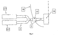
- Figure 3 shows a similar mode of operation as described in Figure 2 , but for two air conditioners 117 and 217 installed in parallel. Using two air conditioners 117, 217, two different outlet temperatures may be provided independently of one another, without the mixing temperature at the check valve 15 changing.
- FIG. 4 An exemplary embodiment of the present invention is described in Figure 4 .
- the arrangement displays a first turbine TA having first process air and a second turbine TB having second process air. Furthermore, the arrangement comprises a heat exchanger 11, which obtains hot fresh air from a bleed air system of a turbine of an aircraft, for example, and discharges the heat to temperature-reduced fresh air.
- a fourth pipeline 4 conveys the temperature-reduced fresh air to a second pipeline branch 8, which distributes the temperature-reduced fresh air to a fifth and a sixth pipeline 5, 6.
- the first process air of the first turbine is mixed with the temperature-reduced fresh air of the fifth pipeline 5 at a third pipeline branch 9 and discharged to a first pipeline 1.
- the temperature-reduced fresh air of the sixth pipeline 6 is mixed at a fourth pipeline branch 10 with the second process air of the second turbine TB and fed to a second pipeline 2.
- the first mixed air of the first pipeline 1 and the second mixed air of the second pipeline 2 is fed to a first pipeline branch 7 and relayed to a third pipeline 3.
- the third pipeline 3 conveys third mixed air to an aircraft cabin or other air-conditioning elements, such as a check valve 15.
- a first or second air flow regulating valve 12, 13 may be situated in the fifth pipeline 5 and in the sixth pipeline 6, respectively.
- the sequence of the method for regulating a process air temperature may be described using Figure 5 .
- the first turbine TA provides first process air and the second turbine TB provides second process air, each having a temperature range from 0 to -8°C.
- temperature-reduced fresh air is provided, whose temperature is 30°C to 100°C, for example.
- the first process air of the first turbine TA may have its temperature increased to 30°C to 45°C by the valve-regulated supply of the temperature-reduced fresh air of the heat exchanger 11, because of which all process air lines downstream from the turbines, such as the first pipeline 1, may not ice.
- the second process air temperature of the second turbine TB may be moved to maximum cooling capacity, by which further ice accumulations in or on the process air lines, such as the second pipeline 2, are prevented, because the critical area from 0°C to -8°C is not passed through. Therefore, the first process air temperature of the first turbine TA and the second process air temperature of the second turbine TB may be kept at a constant temperature value within a second time range B-C. In a time range C-D, both process air temperatures may again be moved to a range from 0 to -8°C.
- the process air temperature of the second turbine TB may be brought to a temperature range from 30 to 45°C and the first process air temperature of the first turbine TA may be brought to maximum cooling capacity of colder than -8°C. Therefore, the second turbine TB may be deiced using the first process air at greater than 0°C.
- the particular downstream components in the first and second pipelines 1, 2 are deiced cyclically and constant third mixed air may be obtained by mixing the process air temperatures with the temperature-reduced fresh air. Temperature oscillations in the cabin may thus be avoided.
Landscapes
- Health & Medical Sciences (AREA)
- General Health & Medical Sciences (AREA)
- Pulmonology (AREA)
- Engineering & Computer Science (AREA)
- Aviation & Aerospace Engineering (AREA)
- Air Conditioning Control Device (AREA)
- Central Air Conditioning (AREA)
- Duct Arrangements (AREA)
- Air-Conditioning For Vehicles (AREA)
- Air-Conditioning Room Units, And Self-Contained Units In General (AREA)
- Defrosting Systems (AREA)
Claims (13)
- Anordnung zur Enteisung von Rohrleitungsverbindungen eines Flugzeugs, wobei die Anordnung alle Frischluftauslässe einer Klimaanlage, einer Turbine oder eines Wärmetauschers umfasst, wobei die Anordnung eine erste Rohrleitung (1), die mit einer ersten Turbine (TA) verbunden ist, und eine zweite Rohrleitung (2), die mit einer zweiten Turbine (TB) verbunden ist, aufweist,
wobei die beiden Rohrleitungen (1, 2), welche sich jeweils stromabwärts von den beiden Turbinen (TA, TB) befinden und denen turbinenausgangsseitig eine Prozessluft eingespeist wird, rohrendseitig verbunden und mit einer dritten Rohrleitung (3) fortgesetzt sind,
wobei eine erste Heißluftquelle (11) ausgangsseitig mit einer vierten Rohrleitung (4) verbunden ist, der eine von der Heißluftquelle (11) temperaturherabgesetzte Frischluft eingespeist wird, und die vierte Rohrleitung (4) zwei weitere ventilgeregelte Rohrleitungen (5, 6) aufweist, die rohrendseitig jeweils mit einem Luftstromregelventil (12, 13) zum Regeln des Luftmassenstroms der temperaturherabgesetzten Frischluft verbunden sind, von denen jeweils eine fünfte oder eine sechste Rohrleitung (5, 6) mit der ersten oder der zweiten Rohrleitung (1, 2) verbunden ist, durch die die temperaturherabgesetzte Frischluft transportiert und ventilgeregelt in die erste und/oder zweite Rohrleitung (1, 2) eingespeist wird; und
wobei das erste und/oder zweite Luftstromregelventil (12, 13) mit einem Zeitverzögerungsglied ausgestattet ist, so dass die Luftstromregelventile (12, 13) dazu befähigt sind, ein zeitverzögertes Schalten zwischen Enteisungs- und Kühl-Temperaturbereichen abwechselnd in der ersten und in der zweiten Rohrleitung (1, 2) zu erreichen, ohne die Ausgangstemperatur der dritten Leitung (3) zu beeinflussen. - Anordnung nach Anspruch 1,
wobei die Heißluftquelle einen Wärmetauscher (11) aufweist; dem Wärmetauscher (11), heiße Frischluft aus einem Bleed-Air-System des Flugzeugs bereitstellbar ist; der Wärmetauscher (11) dazu eingerichtet ist, die temperaturherabgesetzte Frischluft der vierten Rohrleitung (4) bereitzustellen. - Anordnung nach Anspruch 1 oder 2,
wobei die Heißluftquelle eine Klimaanlage (17) aufweist; die Klimaanlage dazu eingerichtet ist, die temperaturherabgesetzte Frischluft bereitzustellen. - Anordnung nach einem der Ansprüche 1 bis 3,
wobei die erste Rohrleitung (1) und die zweite Rohrleitung (2) elektrische Heizelemente aufweisen. - Anordnung nach einem der Ansprüche 1 bis 4,
wobei die vierte Rohrleitung (4) rohrendseitig mit einer zweiten Rohrleitungsverzweigung (8) verbunden ist und letztere mit der fünften und sechsten Rohrleitung (5, 6) verbunden ist. - Verfahren zum Regeln einer Prozesslufttemperatur von transportierter Prozessluft in Rohrleitungsverbindungen eines Flugzeuges, bei dem die prozessluftführenden Rohrleitungsverbindungen mit einem Frischluftauslass, einer Klimaanlage, einer Turbine oder einem Wärmetauscher verbunden sind, wobei den Rohrleitungsverbindungen die Prozessluft ausgangseitig einer ersten und einer zweiten Turbine (TA, TB) bereitgestellt wird und die Prozessluft darauf folgend jeweils einer turbinennachgeschalteten ersten und einer zweiten Rohrleitung (1, 2) unter Druck eingespeist wird, wobei in einem ersten Schritta) zunächst einer Heißluftquelle (11) vom Bleed-Air-System des Flugzeuges heiße Frischluft zugeführt wird, ausgangsseitig der ersten Heißluftquelle eine temperaturherabgesetzte druckbeaufschlagte Frischluft bereitgestellt wird, die einer ausgangsseitig mit der ersten Heißluftquelle (11) verbundenen vierten Rohrleitung (4) eingespeist und durch letztere transportiert wird, undb) dann die temperaturherabgesetzte Frischluft einer rohrendseitig mit der vierten Rohrleitung (4) verbundenen fünften und einer sechsten Rohrleitung (5, 6) eingeleitet wird, deren Transportc) dann mit einem von der fünften bzw. der sechsten Rohrleitung (5, 6) jeweils abgezweigten Frischluftanteil an temperaturherabgesetzter Frischluft durch diese beiden Rohrleitungen (5, 6) fortgesetzt wird, derd) dann die fünfte und die sechste Rohrleitung (5, 6) ventilgeregelt verlässt und der ersten oder der zweiten Rohrleitung (1, 2) zusätzlich zu der Prozessluft wechselweise eingespeist wird, unde) darauf folgend der Lufttransport durch einen verbleibenden Rohrleitungsabschnitt, welcher der Einspeisungsstelle nach Schritt d) folgt und in der ersten und zweiten Rohrleitung (1, 2) verbleibt, mit einer Mischprozessluft erfolgt,f) die danach in eine der ersten und zweiten Rohrleitung (1, 2) rohrendseitig fortgesetzte dritte Rohrleitung (3) eingespeist wird und mit Nachfolgeeinheiten des Flugzeugs zugeführt wird, die mit der dritten Rohrleitung (3) verbunden sind,wobei das erste und/oder zweite Luftstromregelventil (12, 13) mit einem Zeitverzögerungsglied ausgestattet ist, so dass die Luftstromregelventile (12, 13) so geregelt werden, dass die Prozesslufttemperatur in einer zeitverzögerten Weise zwischen Enteisungs- und Kühl-Temperaturbereichen in der ersten und in der zweiten Rohrleitung (1, 2) abwechselnd geschaltet wird, ohne die Ausgangstemperatur der dritten Leitung (3) zu beeinflussen.
- Verfahren nach Anspruch 6,
wobei sich die Mischprozessluft nach Schritt e) aus der turbinenausgangseitig bereitgestellten Prozessluft und dem abgezweigten Frischluftanteil an temperaturherabgesetzter Frischluft zusammensetzt. - Verfahren nach einem der Ansprüche 6 oder 7,
wobei die Prozessluft variabel durch die wechselweise Einspeisung der ventilgeregelten Frischluftanteile an temperaturherabgesetzter Frischluft nach Schritt d) die Prozessluft variabel temperiert wird. - Verfahren nach den Anspruch 6,
wobeif) die erste und die zweite Turbine (TA, TB) turbinenausgangsseitig zunächst eine Prozessluft bereitstellen, deren Prozesslufttemperatur innerhalb einem ersten Zeitbereich A-B im Teillastbereich von 0°C bis -8°C arbeitet, und gleichfalls während der Betriebszeit des Klimaanlagenbetriebs ausgangsseitig der ersten Heißluftquelle (11) nach Schritt a) eine Temperatur herabgesetzte Frischluft bereitgestellt wird, deren Frischlufttemperatur im Lastbereich von 30°C bis 100°C arbeiten wird, undg) danach die Prozesslufttemperatur der ersten Turbine (TA) durch die ventilgeregelte Zufuhr von jeweils einem Frischluftanteil an Temperatur herabgesetzter Frischluft nach dem Schritt d) auf mindestens 30°C bis 45°C erhöht wird, wodurch alle turbinennachgeschalteten Prozessluftleitungen und in die Prozessluftleitungen integrierte Ventile enteist werden, und gleichzeitig die Prozesslufttemperatur der zweiten Turbine (TB) auf eine Kühlleistung gefahren wird, durch die weitere Eisansammlungen in oder auf den Prozessluftleitungen verhindert werden, wobei diese Prozesslufttemperaturen der beiden Turbinen (TA; TB) innerhalb einem zweiten Zeitbereich B-C auf einem konstanten Temperaturwert gehalten werden, undh) dann die Prozesslufttemperatur der ersten Turbine (TA) und der zweiten Turbine (TB) durch die ventilgeregelte Zufuhr von jeweils einem Frischluftanteil an temperaturherabgesetzter Frischluft nach dem Schritt d) auf eine normale Prozesslufttemperatur gebracht, welche der nach dem Schritt f) entspricht, gebracht wird, wobei diese Prozesslufttemperatur der ersten Turbine (TA) und der zweiten Turbine (TB) innerhalb eines dritten Zeitbereichs C-D auf einem konstanten Temperaturwert gehalten werden, undi) danach die Prozesslufttemperatur der ersten Turbine (TA) auf eine maximale Kühlleistung gefahren wird und gleichzeitig die Prozesslufttemperatur der zweiten Turbine (TB) durch die ventilgeregelte Zufuhr von jeweils einem Frischluftanteil an temperaturherabgesetzter Frischluft nach dem Schritt d) auf 30°C bis 45°C erhöht wird, wodurch Eisansammlungen in oder auf der der zweiten Turbine (TB) nachgeschalteten zweiten Rohrleitung (2), mit der zweiten Rohrleitung (2) verbundenen Rohrleitungen sowie in den Rohrleitungen integrierte Ventile verhindert werden, wobei diese Prozesslufttemperatur der beiden Turbinen (TA, TB) innerhalb einem vierten Zeitbereich D-E auf einem konstanten Temperaturwert gehalten wird, undj) dann die Maßnahmen des Schritts h) wiederholt, mit der Einschränkung, dass die Prozesslufttemperatur der beiden Turbinen (TA, TB) schrittbezogen innerhalb eines fünften Zeitbereichs E-A auf einem konstanten Temperaturwert gehalten werden. - Verfahren nach einem der Ansprüche 6 bis 8,
wobei nach dem Schritt g) mit einem der sechsten Rohrleitung (6) integrierten und zeitverzögert arbeitenden zweiten Luftstrom-Regelventil (13) eine ventilgeregelte Drosselung des jeweiligen Frischluftanteils an temperaturherabgesetzter Frischluft vorgenommen wird, dermaßen, dass die Prozesslufttemperatur der zweiten Turbine (TB) mit einer vordefinierten Zeitverzögerung reduziert wird, bis jene maximale Kühlleistung erreicht wird, sofern die Prozesslufttemperatur der Prozessluft der ersten Turbine (TA) mit einem die fünften Rohrleitung (5) jeweils passierenden Frischluftanteils an temperaturherabgesetzter Frischluft, der durch ein der fünften Rohrleitung (5) integriertes erstes Luftstromregelventil (12) ventilgeregelt wird, erhöht wird. - Verfahren nach Anspruch 6,
dadurch gekennzeichnet, dass nach dem Schritt i) mit dem der fünften Rohrleitung (5) integrierten und zeitverzögert arbeitenden ersten Luftstrom-Regelventil (12) eine ventilgeregelte Drosselung des jeweiligen Frischluftanteils an temperaturherabgesetzter Frischluft vorgenommen wird, dermaßen, dass die Prozesslufttemperatur der ersten Turbine (TA) mit einer vordefinierten Zeitverzögerung reduziert wird, bis die maximale Kühlleistung erreicht wird, sofern die Prozesslufttemperatur der Prozessluft der zweiten Turbine (TB) mit jenem der sechsten Rohrleitung (6) passierenden Frischluftanteil an temperaturherabgesetzter Frischluft, der durch das in die sechsten Rohrleitung (6) integrierte zweite Luftstrom-Regelventil (13) ventilgeregelt wird, erhöht wird. - Verfahren nach Anspruch 9,
wobei die Schritte f) bis j) in der Hauptsache während der Zeitdauer eines Bodenaufenthaltes des Flugzeugs durchgeführt und in der angegebenen Reihenfolge beliebig wiederholt werden - Verfahren nach Anspruch 8,
wobei sich die Durchführung der Schritte f) bis j) auf eine Zeitdauer, die mit dem Zeitraum der Start- und Landephase des Flugzeuges oder während des Fluges bei sehr niedrigen Flughöhen unter 15.000 Fuß korrespondiert, bezieht.
Applications Claiming Priority (3)
| Application Number | Priority Date | Filing Date | Title |
|---|---|---|---|
| US82934806P | 2006-10-13 | 2006-10-13 | |
| DE200610048622 DE102006048622A1 (de) | 2006-10-13 | 2006-10-13 | Optimierte Enteisungsreglung bei parallel geschalteten Frischluftauslässen von Klimaanlagen |
| PCT/EP2007/008898 WO2008043568A1 (en) | 2006-10-13 | 2007-10-12 | Optimized defrosting regulation of parallel arranged fresh air outlets of air conditioners |
Publications (2)
| Publication Number | Publication Date |
|---|---|
| EP2074028A1 EP2074028A1 (de) | 2009-07-01 |
| EP2074028B1 true EP2074028B1 (de) | 2010-12-08 |
Family
ID=39198318
Family Applications (1)
| Application Number | Title | Priority Date | Filing Date |
|---|---|---|---|
| EP20070818969 Not-in-force EP2074028B1 (de) | 2006-10-13 | 2007-10-12 | Optimierte abtauregelungsanordnung und verfahren für parallel angeordneten frischluftauslässen von klimaanlagen |
Country Status (10)
| Country | Link |
|---|---|
| US (2) | US20090255277A1 (de) |
| EP (1) | EP2074028B1 (de) |
| JP (1) | JP5295114B2 (de) |
| CN (1) | CN101522522B (de) |
| AT (1) | ATE490915T1 (de) |
| BR (1) | BRPI0719168A2 (de) |
| CA (1) | CA2664613C (de) |
| DE (2) | DE102006048622A1 (de) |
| RU (1) | RU2446992C2 (de) |
| WO (1) | WO2008043568A1 (de) |
Cited By (1)
| Publication number | Priority date | Publication date | Assignee | Title |
|---|---|---|---|---|
| US10677508B2 (en) | 2017-06-02 | 2020-06-09 | Diehl Aviation Gilching Gmbh | Method for operating a cooling unit and cooling unit configuration for an aircraft |
Families Citing this family (7)
| Publication number | Priority date | Publication date | Assignee | Title |
|---|---|---|---|---|
| DE102008025960B4 (de) * | 2008-05-30 | 2010-10-07 | Airbus Deutschland Gmbh | System zur Ventilation eines Flugzeugbereichs |
| WO2011124390A1 (en) * | 2010-04-09 | 2011-10-13 | Airbus Operations Gmbh | Mixer assembly for an aircraft air conditioning system |
| US10023317B2 (en) * | 2015-06-23 | 2018-07-17 | The Boeing Company | Flight deck takeoff duct and trim air mix muff |
| US11506121B2 (en) | 2016-05-26 | 2022-11-22 | Hamilton Sundstrand Corporation | Multiple nozzle configurations for a turbine of an environmental control system |
| EP3249196B1 (de) | 2016-05-26 | 2020-12-02 | Hamilton Sundstrand Corporation | Energiefluss eines fortschrittlichen klimaregelungssystems |
| US10604263B2 (en) * | 2016-05-26 | 2020-03-31 | Hamilton Sundstrand Corporation | Mixing bleed and ram air using a dual use turbine system |
| US11511867B2 (en) | 2016-05-26 | 2022-11-29 | Hamilton Sundstrand Corporation | Mixing ram and bleed air in a dual entry turbine system |
Family Cites Families (15)
| Publication number | Priority date | Publication date | Assignee | Title |
|---|---|---|---|---|
| GB880616A (en) * | 1959-02-18 | 1961-10-25 | Kidde Walter Co Ltd | Improvements in or relating to aircraft breathing systems |
| US4482114A (en) * | 1981-01-26 | 1984-11-13 | The Boeing Company | Integrated thermal anti-icing and environmental control system |
| US4684081A (en) * | 1986-06-11 | 1987-08-04 | Lockheed Corporation | Multifunction power system for an aircraft |
| US5704218A (en) * | 1996-04-08 | 1998-01-06 | United Technologies Corporation | Integrated environmental control system |
| US5967461A (en) * | 1997-07-02 | 1999-10-19 | Mcdonnell Douglas Corp. | High efficiency environmental control systems and methods |
| US6427471B1 (en) * | 2000-02-29 | 2002-08-06 | Shimadzu Corporation | Air cycle machine and air conditioning system using the same |
| GB0122672D0 (en) * | 2001-09-20 | 2001-11-14 | Honeywell Normalair Garrett | Environmental control systems |
| DE10201427A1 (de) * | 2002-01-16 | 2003-07-24 | Liebherr Aerospace Gmbh | System zur Luftentfeuchtung in Klimaanlagen |
| DE10247335B3 (de) | 2002-10-10 | 2004-04-08 | Liebherr-Aerospace Lindenberg Gmbh | Kondensor |
| US7210653B2 (en) * | 2002-10-22 | 2007-05-01 | The Boeing Company | Electric-based secondary power system architectures for aircraft |
| DE10301465B4 (de) * | 2003-01-16 | 2007-07-12 | Liebherr-Aerospace Lindenberg Gmbh | Klimatisierungssystem |
| US7000425B2 (en) * | 2003-03-12 | 2006-02-21 | Hamilton Sundstrand | Manifold for pack and a half condensing cycle pack with combined heat exchangers |
| DE102004039667A1 (de) * | 2004-08-16 | 2006-03-02 | Airbus Deutschland Gmbh | Luftversorgung in einem Flugzeug |
| RU2281435C1 (ru) * | 2005-03-14 | 2006-08-10 | Олег Савельевич Кочетов | Кондиционер |
| FR2913402B1 (fr) * | 2007-03-07 | 2009-11-27 | Airbus France | Aeronef comportant un systeme de conditionnement d'air. |
-
2006
- 2006-10-13 DE DE200610048622 patent/DE102006048622A1/de not_active Withdrawn
-
2007
- 2007-10-12 JP JP2009531786A patent/JP5295114B2/ja not_active Expired - Fee Related
- 2007-10-12 CN CN2007800380742A patent/CN101522522B/zh not_active Expired - Fee Related
- 2007-10-12 CA CA2664613A patent/CA2664613C/en not_active Expired - Fee Related
- 2007-10-12 BR BRPI0719168 patent/BRPI0719168A2/pt not_active IP Right Cessation
- 2007-10-12 RU RU2009117473/11A patent/RU2446992C2/ru not_active IP Right Cessation
- 2007-10-12 WO PCT/EP2007/008898 patent/WO2008043568A1/en not_active Ceased
- 2007-10-12 EP EP20070818969 patent/EP2074028B1/de not_active Not-in-force
- 2007-10-12 DE DE200760011086 patent/DE602007011086D1/de active Active
- 2007-10-12 AT AT07818969T patent/ATE490915T1/de not_active IP Right Cessation
-
2009
- 2009-04-09 US US12/421,086 patent/US20090255277A1/en not_active Abandoned
-
2012
- 2012-04-30 US US13/460,505 patent/US8480028B2/en not_active Expired - Fee Related
Cited By (1)
| Publication number | Priority date | Publication date | Assignee | Title |
|---|---|---|---|---|
| US10677508B2 (en) | 2017-06-02 | 2020-06-09 | Diehl Aviation Gilching Gmbh | Method for operating a cooling unit and cooling unit configuration for an aircraft |
Also Published As
| Publication number | Publication date |
|---|---|
| CA2664613A1 (en) | 2008-04-17 |
| JP2010505696A (ja) | 2010-02-25 |
| WO2008043568A1 (en) | 2008-04-17 |
| DE102006048622A1 (de) | 2008-04-24 |
| ATE490915T1 (de) | 2010-12-15 |
| RU2446992C2 (ru) | 2012-04-10 |
| US20090255277A1 (en) | 2009-10-15 |
| EP2074028A1 (de) | 2009-07-01 |
| DE602007011086D1 (de) | 2011-01-20 |
| JP5295114B2 (ja) | 2013-09-18 |
| CN101522522B (zh) | 2013-06-05 |
| US8480028B2 (en) | 2013-07-09 |
| RU2009117473A (ru) | 2010-11-20 |
| BRPI0719168A2 (pt) | 2014-04-15 |
| US20120273051A1 (en) | 2012-11-01 |
| CA2664613C (en) | 2015-04-28 |
| CN101522522A (zh) | 2009-09-02 |
Similar Documents
| Publication | Publication Date | Title |
|---|---|---|
| US8480028B2 (en) | Optimized defrosting regulation of parallel arranged fresh air outlets of air conditioners | |
| US10669032B2 (en) | Blended flow air cycle system for environmental control | |
| CA2768929C (en) | Environmental control system supply precooler bypass | |
| EP3002431B1 (de) | Zapfluftsystem eines triebwerks | |
| US10125683B2 (en) | De-icing and conditioning device for an aircraft | |
| RU2455200C2 (ru) | Система кондиционирования воздуха с защитой от обледенения для воздушного судна | |
| US10011361B2 (en) | Aircraft environmental control system providing improved performance and backup temperature control | |
| EP3173337B1 (de) | Flugzeugklimatisierungssystem mit umgebungsluftzufuhr und verfahren zum betrieb solch eines flugzeugklimatisierungssystems | |
| JP2001296070A (ja) | 輸送飛行機用の冗長的および段階的再循環混合装置を備えた高出力空調装置 | |
| US20140144163A1 (en) | Aircraft air conditioning system and method of operating an aircraft air conditioning system | |
| EP2735510A1 (de) | Flugzeugklimaanlage und Verfahren für den Betrieb einer Flugzeugklimaanlage | |
| EP4292937B1 (de) | Durch stauluftturbine angetriebener kabinenluftverdichter | |
| US20250263170A1 (en) | Aircraft Hybrid Cooling System | |
| EP3303135A1 (de) | Elektrisches hybridfahrzeug | |
| EP4147973B1 (de) | Trimmluftwärmetauscher für eine klimaanlage | |
| US20250341188A1 (en) | Integrated turbine engine bleed system | |
| CN115817817A (zh) | 运载工具、环境控制系统和操作环境控制系统的方法 |
Legal Events
| Date | Code | Title | Description |
|---|---|---|---|
| PUAI | Public reference made under article 153(3) epc to a published international application that has entered the european phase |
Free format text: ORIGINAL CODE: 0009012 |
|
| 17P | Request for examination filed |
Effective date: 20090409 |
|
| AK | Designated contracting states |
Kind code of ref document: A1 Designated state(s): AT BE BG CH CY CZ DE DK EE ES FI FR GB GR HU IE IS IT LI LT LU LV MC MT NL PL PT RO SE SI SK TR |
|
| AX | Request for extension of the european patent |
Extension state: AL BA HR MK RS |
|
| RIN1 | Information on inventor provided before grant (corrected) |
Inventor name: KELNHOFER, JUERGEN Inventor name: FRANCISCO-PALOMARES, JOSE-JAVIER Inventor name: KRAKOWSKI, DARIUSZ |
|
| 17Q | First examination report despatched |
Effective date: 20091014 |
|
| GRAP | Despatch of communication of intention to grant a patent |
Free format text: ORIGINAL CODE: EPIDOSNIGR1 |
|
| RTI1 | Title (correction) |
Free format text: OPTIMIZED DEFROSTING REGULATION ARRANGEMENT AND METHOD FOR PARALLEL ARRANGED FRESH AIR OUTLETS OF AIR CONDITIONERS |
|
| GRAS | Grant fee paid |
Free format text: ORIGINAL CODE: EPIDOSNIGR3 |
|
| RAP1 | Party data changed (applicant data changed or rights of an application transferred) |
Owner name: AIRBUS OPERATIONS GMBH |
|
| GRAA | (expected) grant |
Free format text: ORIGINAL CODE: 0009210 |
|
| AK | Designated contracting states |
Kind code of ref document: B1 Designated state(s): AT BE BG CH CY CZ DE DK EE ES FI FR GB GR HU IE IS IT LI LT LU LV MC MT NL PL PT RO SE SI SK TR |
|
| REG | Reference to a national code |
Ref country code: GB Ref legal event code: FG4D |
|
| REG | Reference to a national code |
Ref country code: CH Ref legal event code: EP |
|
| REG | Reference to a national code |
Ref country code: IE Ref legal event code: FG4D |
|
| REF | Corresponds to: |
Ref document number: 602007011086 Country of ref document: DE Date of ref document: 20110120 Kind code of ref document: P |
|
| REG | Reference to a national code |
Ref country code: NL Ref legal event code: VDEP Effective date: 20101208 |
|
| PG25 | Lapsed in a contracting state [announced via postgrant information from national office to epo] |
Ref country code: LT Free format text: LAPSE BECAUSE OF FAILURE TO SUBMIT A TRANSLATION OF THE DESCRIPTION OR TO PAY THE FEE WITHIN THE PRESCRIBED TIME-LIMIT Effective date: 20101208 |
|
| LTIE | Lt: invalidation of european patent or patent extension |
Effective date: 20101208 |
|
| PG25 | Lapsed in a contracting state [announced via postgrant information from national office to epo] |
Ref country code: SE Free format text: LAPSE BECAUSE OF FAILURE TO SUBMIT A TRANSLATION OF THE DESCRIPTION OR TO PAY THE FEE WITHIN THE PRESCRIBED TIME-LIMIT Effective date: 20101208 Ref country code: CY Free format text: LAPSE BECAUSE OF FAILURE TO SUBMIT A TRANSLATION OF THE DESCRIPTION OR TO PAY THE FEE WITHIN THE PRESCRIBED TIME-LIMIT Effective date: 20101208 Ref country code: NL Free format text: LAPSE BECAUSE OF FAILURE TO SUBMIT A TRANSLATION OF THE DESCRIPTION OR TO PAY THE FEE WITHIN THE PRESCRIBED TIME-LIMIT Effective date: 20101208 Ref country code: BG Free format text: LAPSE BECAUSE OF FAILURE TO SUBMIT A TRANSLATION OF THE DESCRIPTION OR TO PAY THE FEE WITHIN THE PRESCRIBED TIME-LIMIT Effective date: 20110308 Ref country code: FI Free format text: LAPSE BECAUSE OF FAILURE TO SUBMIT A TRANSLATION OF THE DESCRIPTION OR TO PAY THE FEE WITHIN THE PRESCRIBED TIME-LIMIT Effective date: 20101208 Ref country code: AT Free format text: LAPSE BECAUSE OF FAILURE TO SUBMIT A TRANSLATION OF THE DESCRIPTION OR TO PAY THE FEE WITHIN THE PRESCRIBED TIME-LIMIT Effective date: 20101208 Ref country code: LV Free format text: LAPSE BECAUSE OF FAILURE TO SUBMIT A TRANSLATION OF THE DESCRIPTION OR TO PAY THE FEE WITHIN THE PRESCRIBED TIME-LIMIT Effective date: 20101208 Ref country code: SI Free format text: LAPSE BECAUSE OF FAILURE TO SUBMIT A TRANSLATION OF THE DESCRIPTION OR TO PAY THE FEE WITHIN THE PRESCRIBED TIME-LIMIT Effective date: 20101208 |
|
| PG25 | Lapsed in a contracting state [announced via postgrant information from national office to epo] |
Ref country code: BE Free format text: LAPSE BECAUSE OF FAILURE TO SUBMIT A TRANSLATION OF THE DESCRIPTION OR TO PAY THE FEE WITHIN THE PRESCRIBED TIME-LIMIT Effective date: 20101208 Ref country code: ES Free format text: LAPSE BECAUSE OF FAILURE TO SUBMIT A TRANSLATION OF THE DESCRIPTION OR TO PAY THE FEE WITHIN THE PRESCRIBED TIME-LIMIT Effective date: 20110319 Ref country code: GR Free format text: LAPSE BECAUSE OF FAILURE TO SUBMIT A TRANSLATION OF THE DESCRIPTION OR TO PAY THE FEE WITHIN THE PRESCRIBED TIME-LIMIT Effective date: 20110309 Ref country code: IS Free format text: LAPSE BECAUSE OF FAILURE TO SUBMIT A TRANSLATION OF THE DESCRIPTION OR TO PAY THE FEE WITHIN THE PRESCRIBED TIME-LIMIT Effective date: 20110408 Ref country code: EE Free format text: LAPSE BECAUSE OF FAILURE TO SUBMIT A TRANSLATION OF THE DESCRIPTION OR TO PAY THE FEE WITHIN THE PRESCRIBED TIME-LIMIT Effective date: 20101208 Ref country code: PT Free format text: LAPSE BECAUSE OF FAILURE TO SUBMIT A TRANSLATION OF THE DESCRIPTION OR TO PAY THE FEE WITHIN THE PRESCRIBED TIME-LIMIT Effective date: 20110408 Ref country code: CZ Free format text: LAPSE BECAUSE OF FAILURE TO SUBMIT A TRANSLATION OF THE DESCRIPTION OR TO PAY THE FEE WITHIN THE PRESCRIBED TIME-LIMIT Effective date: 20101208 |
|
| PG25 | Lapsed in a contracting state [announced via postgrant information from national office to epo] |
Ref country code: PL Free format text: LAPSE BECAUSE OF FAILURE TO SUBMIT A TRANSLATION OF THE DESCRIPTION OR TO PAY THE FEE WITHIN THE PRESCRIBED TIME-LIMIT Effective date: 20101208 Ref country code: SK Free format text: LAPSE BECAUSE OF FAILURE TO SUBMIT A TRANSLATION OF THE DESCRIPTION OR TO PAY THE FEE WITHIN THE PRESCRIBED TIME-LIMIT Effective date: 20101208 Ref country code: RO Free format text: LAPSE BECAUSE OF FAILURE TO SUBMIT A TRANSLATION OF THE DESCRIPTION OR TO PAY THE FEE WITHIN THE PRESCRIBED TIME-LIMIT Effective date: 20101208 |
|
| PLBE | No opposition filed within time limit |
Free format text: ORIGINAL CODE: 0009261 |
|
| STAA | Information on the status of an ep patent application or granted ep patent |
Free format text: STATUS: NO OPPOSITION FILED WITHIN TIME LIMIT |
|
| PG25 | Lapsed in a contracting state [announced via postgrant information from national office to epo] |
Ref country code: DK Free format text: LAPSE BECAUSE OF FAILURE TO SUBMIT A TRANSLATION OF THE DESCRIPTION OR TO PAY THE FEE WITHIN THE PRESCRIBED TIME-LIMIT Effective date: 20101208 |
|
| 26N | No opposition filed |
Effective date: 20110909 |
|
| REG | Reference to a national code |
Ref country code: DE Ref legal event code: R097 Ref document number: 602007011086 Country of ref document: DE Effective date: 20110909 |
|
| PG25 | Lapsed in a contracting state [announced via postgrant information from national office to epo] |
Ref country code: MC Free format text: LAPSE BECAUSE OF NON-PAYMENT OF DUE FEES Effective date: 20111031 |
|
| REG | Reference to a national code |
Ref country code: CH Ref legal event code: PL |
|
| PG25 | Lapsed in a contracting state [announced via postgrant information from national office to epo] |
Ref country code: CH Free format text: LAPSE BECAUSE OF NON-PAYMENT OF DUE FEES Effective date: 20111031 Ref country code: LI Free format text: LAPSE BECAUSE OF NON-PAYMENT OF DUE FEES Effective date: 20111031 |
|
| REG | Reference to a national code |
Ref country code: IE Ref legal event code: MM4A |
|
| PG25 | Lapsed in a contracting state [announced via postgrant information from national office to epo] |
Ref country code: IE Free format text: LAPSE BECAUSE OF NON-PAYMENT OF DUE FEES Effective date: 20111012 |
|
| PG25 | Lapsed in a contracting state [announced via postgrant information from national office to epo] |
Ref country code: MT Free format text: LAPSE BECAUSE OF FAILURE TO SUBMIT A TRANSLATION OF THE DESCRIPTION OR TO PAY THE FEE WITHIN THE PRESCRIBED TIME-LIMIT Effective date: 20101208 |
|
| PG25 | Lapsed in a contracting state [announced via postgrant information from national office to epo] |
Ref country code: LU Free format text: LAPSE BECAUSE OF NON-PAYMENT OF DUE FEES Effective date: 20111012 |
|
| PG25 | Lapsed in a contracting state [announced via postgrant information from national office to epo] |
Ref country code: TR Free format text: LAPSE BECAUSE OF FAILURE TO SUBMIT A TRANSLATION OF THE DESCRIPTION OR TO PAY THE FEE WITHIN THE PRESCRIBED TIME-LIMIT Effective date: 20101208 |
|
| PG25 | Lapsed in a contracting state [announced via postgrant information from national office to epo] |
Ref country code: HU Free format text: LAPSE BECAUSE OF FAILURE TO SUBMIT A TRANSLATION OF THE DESCRIPTION OR TO PAY THE FEE WITHIN THE PRESCRIBED TIME-LIMIT Effective date: 20101208 |
|
| REG | Reference to a national code |
Ref country code: FR Ref legal event code: PLFP Year of fee payment: 9 |
|
| REG | Reference to a national code |
Ref country code: DE Ref legal event code: R082 Ref document number: 602007011086 Country of ref document: DE Representative=s name: LKGLOBAL | LORENZ & KOPF PARTG MBB PATENTANWAE, DE Ref country code: DE Ref legal event code: R082 Ref document number: 602007011086 Country of ref document: DE Representative=s name: KOPF WESTENBERGER WACHENHAUSEN PATENTANWAELTE , DE |
|
| REG | Reference to a national code |
Ref country code: FR Ref legal event code: PLFP Year of fee payment: 10 |
|
| PGFP | Annual fee paid to national office [announced via postgrant information from national office to epo] |
Ref country code: IT Payment date: 20161024 Year of fee payment: 10 |
|
| REG | Reference to a national code |
Ref country code: FR Ref legal event code: PLFP Year of fee payment: 11 |
|
| REG | Reference to a national code |
Ref country code: FR Ref legal event code: PLFP Year of fee payment: 12 |
|
| PG25 | Lapsed in a contracting state [announced via postgrant information from national office to epo] |
Ref country code: IT Free format text: LAPSE BECAUSE OF NON-PAYMENT OF DUE FEES Effective date: 20171012 |
|
| PGFP | Annual fee paid to national office [announced via postgrant information from national office to epo] |
Ref country code: DE Payment date: 20191021 Year of fee payment: 13 |
|
| PGFP | Annual fee paid to national office [announced via postgrant information from national office to epo] |
Ref country code: FR Payment date: 20191028 Year of fee payment: 13 |
|
| PGFP | Annual fee paid to national office [announced via postgrant information from national office to epo] |
Ref country code: GB Payment date: 20191021 Year of fee payment: 13 |
|
| REG | Reference to a national code |
Ref country code: DE Ref legal event code: R119 Ref document number: 602007011086 Country of ref document: DE |
|
| GBPC | Gb: european patent ceased through non-payment of renewal fee |
Effective date: 20201012 |
|
| PG25 | Lapsed in a contracting state [announced via postgrant information from national office to epo] |
Ref country code: DE Free format text: LAPSE BECAUSE OF NON-PAYMENT OF DUE FEES Effective date: 20210501 Ref country code: FR Free format text: LAPSE BECAUSE OF NON-PAYMENT OF DUE FEES Effective date: 20201031 |
|
| PG25 | Lapsed in a contracting state [announced via postgrant information from national office to epo] |
Ref country code: GB Free format text: LAPSE BECAUSE OF NON-PAYMENT OF DUE FEES Effective date: 20201012 |