EP2074301B1 - Fan-triebwerk mit schubdüsenkontrolle für start und landung - Google Patents
Fan-triebwerk mit schubdüsenkontrolle für start und landung Download PDFInfo
- Publication number
- EP2074301B1 EP2074301B1 EP06851139.3A EP06851139A EP2074301B1 EP 2074301 B1 EP2074301 B1 EP 2074301B1 EP 06851139 A EP06851139 A EP 06851139A EP 2074301 B1 EP2074301 B1 EP 2074301B1
- Authority
- EP
- European Patent Office
- Prior art keywords
- take
- turbofan engine
- turbofan
- landing
- response
- Prior art date
- Legal status (The legal status is an assumption and is not a legal conclusion. Google has not performed a legal analysis and makes no representation as to the accuracy of the status listed.)
- Active
Links
Images


Classifications
-
- F—MECHANICAL ENGINEERING; LIGHTING; HEATING; WEAPONS; BLASTING
- F02—COMBUSTION ENGINES; HOT-GAS OR COMBUSTION-PRODUCT ENGINE PLANTS
- F02K—JET-PROPULSION PLANTS
- F02K1/00—Plants characterised by the form or arrangement of the jet pipe or nozzle; Jet pipes or nozzles peculiar thereto
- F02K1/002—Plants characterised by the form or arrangement of the jet pipe or nozzle; Jet pipes or nozzles peculiar thereto with means to modify the direction of thrust vector
-
- F—MECHANICAL ENGINEERING; LIGHTING; HEATING; WEAPONS; BLASTING
- F02—COMBUSTION ENGINES; HOT-GAS OR COMBUSTION-PRODUCT ENGINE PLANTS
- F02K—JET-PROPULSION PLANTS
- F02K1/00—Plants characterised by the form or arrangement of the jet pipe or nozzle; Jet pipes or nozzles peculiar thereto
- F02K1/06—Varying effective area of jet pipe or nozzle
- F02K1/12—Varying effective area of jet pipe or nozzle by means of pivoted flaps
- F02K1/1207—Varying effective area of jet pipe or nozzle by means of pivoted flaps of one series of flaps hinged at their upstream ends on a fixed structure
-
- F—MECHANICAL ENGINEERING; LIGHTING; HEATING; WEAPONS; BLASTING
- F02—COMBUSTION ENGINES; HOT-GAS OR COMBUSTION-PRODUCT ENGINE PLANTS
- F02K—JET-PROPULSION PLANTS
- F02K1/00—Plants characterised by the form or arrangement of the jet pipe or nozzle; Jet pipes or nozzles peculiar thereto
- F02K1/06—Varying effective area of jet pipe or nozzle
- F02K1/15—Control or regulation
-
- F—MECHANICAL ENGINEERING; LIGHTING; HEATING; WEAPONS; BLASTING
- F02—COMBUSTION ENGINES; HOT-GAS OR COMBUSTION-PRODUCT ENGINE PLANTS
- F02K—JET-PROPULSION PLANTS
- F02K3/00—Plants including a gas turbine driving a compressor or a ducted fan
- F02K3/02—Plants including a gas turbine driving a compressor or a ducted fan in which part of the working fluid by-passes the turbine and combustion chamber
- F02K3/04—Plants including a gas turbine driving a compressor or a ducted fan in which part of the working fluid by-passes the turbine and combustion chamber the plant including ducted fans, i.e. fans with high volume, low pressure outputs, for augmenting the jet thrust, e.g. of double-flow type
- F02K3/06—Plants including a gas turbine driving a compressor or a ducted fan in which part of the working fluid by-passes the turbine and combustion chamber the plant including ducted fans, i.e. fans with high volume, low pressure outputs, for augmenting the jet thrust, e.g. of double-flow type with front fan
-
- Y—GENERAL TAGGING OF NEW TECHNOLOGICAL DEVELOPMENTS; GENERAL TAGGING OF CROSS-SECTIONAL TECHNOLOGIES SPANNING OVER SEVERAL SECTIONS OF THE IPC; TECHNICAL SUBJECTS COVERED BY FORMER USPC CROSS-REFERENCE ART COLLECTIONS [XRACs] AND DIGESTS
- Y02—TECHNOLOGIES OR APPLICATIONS FOR MITIGATION OR ADAPTATION AGAINST CLIMATE CHANGE
- Y02T—CLIMATE CHANGE MITIGATION TECHNOLOGIES RELATED TO TRANSPORTATION
- Y02T50/00—Aeronautics or air transport
- Y02T50/60—Efficient propulsion technologies, e.g. for aircraft
Definitions
- This invention relates to thrust vectoring during take-off and/or landing of an aircraft using, for example, a turbofan engine.
- Take-off field length is an important parameter for large commercial aircraft. Enabling a commercial aircraft to utilize a shorter field length enables the aircraft to operate at a greater number of airport facilities.
- the take-off field length requirement is affected by factors such as aircraft gross take-off weight, aircraft aerodynamics, engine performance and operating environment. These same parameters also affect the ability of the aircraft to land on shorter fields.
- US 2003/070417 A1 discloses a thrust vector controller for jet propulsion engines comprising a housing disposed around a jet engine exhaust.
- the housing supports four brackets, in each of which a vane is pivotally installed.
- the vanes are independently controllable to constrict exhaust flow through each bracket.
- US-A-3,020,714 discloses a device for controlling the jets of a propulsion motor.
- the device comprises retractable members mounted at the periphery of a discharge nozzle which can be caused to project into the jet.
- the members are terminated by auxiliary nozzles supplied with compressed air to form transverse auxiliary jets in the centre of the propulsive jet.
- US 2004/216446 A1 discloses a device for controlling propulsive gas mixing at an outlet of an aircraft jet engine, wherein propulsive jets are composed of a hot primary jet exiting from a nozzle of the jet engine and a secondary flux flowing between an external wall of the nozzle and an internal wall of the jet engine.
- the device is for reducing noise generated by jet engines of civil transport aircraft, vectorization in the case of military aircraft or an increase in lift in the case of civil transport aircraft.
- a turbofan engine comprising: a turbofan engine control system; a core nacelle housing a compressor and a turbine, the core nacelle including a low spool supporting the compressor and turbine, the low spool rotationally driving the turbofan through a gear train; a turbofan arranged upstream from the core nacelle and surrounded by a fan nacelle; a bypass flow path downstream from the turbofan and arranged between the core and fan nacelles, the bypass flow path including a nozzle exit area; characterised in that the system comprises a controller programmed to detect at least one of a take-off condition and a landing condition, the controller being programmed to effectively alter the nozzle exit area to achieve a thrust vector in response to the at least one take-off and landing conditions.
- a method of controlling a turbofan engine comprising the steps of: a) determining at least one of a take-off condition and a landing condition; b) effectively altering a turbofan bypass flow nozzle exit area in response to performing step a); c) changing a thrust vector for the at least one take-off and landing conditions; and d) discontinuing the changed thrust vector in response to an aircraft achieving a predetermined velocity.
- the controller preferably determines the take-off and landing conditions using various sensors that are typically indicative of those conditions.
- the nozzle exit area is effectively changed, for example, by manipulating hinged flaps to achieve the thrust vector.
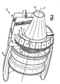
- a geared turbofan engine 10 is shown in Figure 1 .
- a pylon 38 secures the engine 10 to the aircraft.
- the engine 10 includes a core nacelle 12 that houses a low spool 14 and high spool 24 rotatable about an axis A.
- the low spool 14 supports a low pressure compressor 16 and low pressure turbine 18.
- the low spool 14 drives a turbofan 20 through a gear train 22.
- the high spool 24 supports a high pressure compressor 26 and high pressure turbine 28.
- a combustor 30 is arranged between the high pressure compressor 26 and high pressure turbine 28. Compressed air from compressors 16, 26 mixes with fuel from the combustor 30 and is expanded in turbines 18, 28.
- the engine 10 is a high bypass turbofan arrangement.
- the bypass ratio is greater than 10: 1
- the turbofan diameter is substantially larger than the diameter of the low pressure compressor 16.
- the low pressure turbine 18 has a pressure ratio that is greater than 5: 1, in one example.
- the gear train 22 is an epicycle gear train, for example, a star gear train, providing a gear reduction ratio of greater than 2.5:1. It should be understood, however, that the above parameters are only exemplary of a contemplated geared turbofan engine. That is, the invention is applicable to other engines including direct drive turbofans.
- the turbofan 20 directs air into the core nacelle 12, which is used to drive the turbines 18, 28, as is known in the art.
- Turbine exhaust E exits the core nacelle 12 once it has been expanded in the turbines 18, 28, in a passage provided between the core nacelle and a tail cone 32.
- the core nacelle 12 is supported within the fan nacelle 34 by structure 36, which are commonly referred to as upper and lower bifurcations.
- a generally annular bypass flow path 39 is arranged between the core and fan nacelles 12, 34.
- the example illustrated in Figure 1 depicts a high bypass flow arrangement in which approximately eighty percent of the airflow entering the fan nacelle 34 bypasses the core nacelle 12.
- the bypass flow B within the bypass flow path 39 exits the fan nacelle 34 through a nozzle exit area 40.
- Thrust is a function of density, velocity and area. One or more of these parameters can be manipulated to vary the amount and direction of thrust provided by the bypass flow B.
- the engine 10 includes a structure associated with the nozzle exit area 40 to change the physical area and geometry to manipulate the thrust provided by the bypass flow B.
- the nozzle exit area may be effectively altered by other than structural changes, for example, by altering the boundary layer, which changes the flow velocity.
- any device used to effectively change the nozzle exit area is not limited to physical locations near the exit of the fan nacelle 34, but rather, includes altering the bypass flow B at any suitable location.
- the engine 10 has a flow control device 41 ( Figure 3 ) that is used to effectively change the nozzle exit area.
- the flow control device 41 provides the fan nozzle exit area 40 for discharging axially the bypass flow B pressurized by the upstream turbofan 20 of the engine 10. A significant amount of thrust is provided by the bypass flow B due to the high bypass ratio.
- the turbofan 20 of the engine 10 is typically designed for a particular flight condition, typically cruise at 0.8M and 35,000 feet.
- the turbofan 20 is designed at a particular fixed stagger angle for an efficient cruise condition.
- the flow control device 41 is operated to vary the nozzle exit area 40 to adjust fan bypass air flow such that the angle of attack or incidence on the fan blade is maintained close to design incidence at other flight conditions, such as landing and takeoff.
- the flow control device 41 defines a nominal converged position for the nozzle exit area 40 at cruise and climb conditions, and radially opens relative thereto to define a diverged position for other flight conditions.
- the flow control device 41 provides an approximately 20% change in the nozzle exit area 40.
- the flow control device 41 includes multiple hinged flaps 42 ( Figure 2 ) arranged circumferentially about the rear of the fan nacelle 34.
- the hinged flaps 42 can be actuated independently and/or in groups using segments 44.
- the segments 44 and each hinged flap 42 can be moved angularly using actuators 46.
- the segments 44 are guided by tracks 48 in one example.
- the hinged flaps 42 may be manipulated to change the amount and/or direction of thrust.
- the thrust vector is changed by effectively altering the nozzle exit area 40 so that an aircraft can utilize a shorter field.
- a geometry of the nozzle exit area 40 is physically changed using the hinged flaps 42.
- Figure 3 illustrates a downward thrust vector that assists the aircraft during take-off and landing.
- the thrust vector used in a particular application depends upon the location of the engine relative to the aircraft's center of gravity.
- the segments 44 are arranged in quadrants, and the upper quadrants are manipulated as a pair and the lower quadrants are manipulated as a pair to achieve the downward thrust vector.
- the nozzle is varied to angle the thrust axies downward causing a component of the thrust to act as a net lifting force on the aircraft.
- the lifting force directly adds to the aerodynamic lift of the aircraft reducing the required aircraft take-off velocity and, thus, reduces the required take-off field length.
- the control system includes a controller 50 that communicates with the actuators 46, which manipulate the segments 44. Additional or alternative components to those discussed below can be used to communicate with the controller 50, which is programmed to manipulate the flow control device 41.
- the controller 50 commands the actuators 46 to achieve a downward thrust vector in response to, for example, a weight sensor 52 and a full throttle position indicator 54, which are indicative of a take-off condition.
- the weight sensor 52 is used to determine when the aircraft is on the ground.
- the controller 50 commands the actuators 46 to achieve a normal thrust vector once a predetermined aircraft velocity has been achieved subsequent to take-off.
- the normal thrust vector may provide a small downward thrust that is typical in fixed nozzle turbofan engines. Accordingly, the thrust vector achieved by the flow control device 41 is in addition to any normal thrust vector.
- the aircraft velocity is detected with an air speed sensor 60 and communicated to the controller 50.
- the controller 50 also commands the actuators 46 to achieve a downward thrust vector in response to, for example, a full flap condition 56 indicative of the landing condition. In one example, the controller 50 commands the actuators 46 to achieve a normal thrust vector in response to actuation of a switch 58 by the pilot when the aircraft is taxing subsequent to landing.
- an upward thrust vector can be used to reduce the overall trim drag related to operation of the aircraft aero-control surfaces. Additionally, the overall size and weight of the horizontal tails could be reduced.
Landscapes
- Engineering & Computer Science (AREA)
- Chemical & Material Sciences (AREA)
- Combustion & Propulsion (AREA)
- Mechanical Engineering (AREA)
- General Engineering & Computer Science (AREA)
- Structures Of Non-Positive Displacement Pumps (AREA)
- Control Of Turbines (AREA)
Claims (15)
- Fan-Triebwerk, umfassend:ein Fan-Triebwerkssteuerungssystem;eine Kern-Gondel (12), in der ein Verdichter (16) und eine Turbine (18) aufgenommen sind, wobei die Kern-Gondel eine untere Welle (14) umfasst, die den Kompressor und die Turbine unterstützt, wobei die untere Welle das Fan-Triebwerk durch einen Getriebezug (22) mit einer Drehbewegung antreibt;ein Gebläse (20), welches stromaufwärts der Kern-Gondel angeordnet, und von einer Fan-Gondel (34) umgeben ist; undeinen Bypass-Strömungspfad (39) stromabwärts des Fan-Triebwerks, der zwischen der Kern- und Fan-Gondel angeordnet ist, wobei der Bypass-Strömungspfad eine Düsenaustrittsfläche (40) umfasst,dadurch gekennzeichnet, dass das System eine Steuerung (50) umfasst, die programmiert ist, um mindestens eine von einer Startbedingung und einer Landebedingung zu erkennen, wobei die Steuerung programmiert ist, um die Düsenaustrittsfläche wirksam zu ändern, um einen Schubvektor als Reaktion auf die mindestens eine Start- und Landebedingung zu erreichen.
- Fan-Triebwerk nach Anspruch 1, wobei die Kerngondel eine obere Welle (24) aufweist, die einen Hochdruckkompressor (26) und eine Hochdruckturbine (28) unterstützt.
- Fan-Triebwerk nach Anspruch 2, wobei die obere (24) und die untere Welle (14) und das Gebläse (20) ein Bypass-Verhältnis bereitstellen, welches größer ist als 10:1; und/oder
wobei die Turbine (18) der unteren Welle (14) ein Druckverhältnis umfasst, welches größer ist als 5:1; und/oder
wobei der Getriebezug (22) ein Ganguntersetzungsverhältnis größer als 2,5:1 aufweist. - Fan-Triebwerk nach Anspruch 1, 2 oder 3, umfassend eine Strömungssteuerungsvorrichtung, die ein Stellglied (46) zum physikalischen Ändern der Düsenaustrittsfläche als Reaktion auf die mindestens eine Start- und Landebedingung umfasst.
- Fan-Triebwerk nach Anspruch 4, wobei die Strömungssteuerungsvorrichtung (42) Klappen umfasst, die als Reaktion auf das Stellglied zum Ändern des Schubvektors bewegbar sind.
- Fan-Triebwerk nach Anspruch 4, wobei eine Geometrie der Düsenaustrittsfläche (40) als Reaktion auf die mindestens eine Start- und Landebedingung geändert wird.
- Fan-Triebwerk nach einem der vorangegangenen Ansprüche, wobei die Startbedingung eine maximale Startdrossel umfasst; und/oder wobei die Startbedingung ein Gewicht umfasst, welches hinweisend auf ein Gewicht eines Flugzeugs am Boden ist.
- Fan-Triebwerk nach Anspruch 7, wobei die Steuerung programmiert ist, um den Schubvektor als Reaktion darauf abzubrechen, wenn ein Flugzeug eine zuvor festgelegte Geschwindigkeit erreicht.
- Fan-Triebwerk nach einem der vorangegangenen Ansprüche, wobei die Landebedingung das Initiieren einer Landung umfasst, die vorzugsweise das Einschalten aller Klappen nach unten umfasst.
- Fan-Triebwerk nach Anspruch 9, wobei die Steuerung programmiert ist, um den Schubvektor als Reaktion auf einen manuell von einem Piloten bereitgestellten Befehl abzubrechen.
- Verfahren zur Steuerung eines Fan-Triebwerks, umfassend die folgenden Schritte:a) Bestimmen mindestens einer von einer Startbedingung und einer Landebedingung;b) wirksames Verändern einer Fan-Triebwerk-Bypass-Strömungsdüsenaustrittsfläche (40) als Reaktion auf die Ausführung von Schritt a);c) Ändern eines Schubvektors für die mindestens eine Start- und Landebedingung; undd) Abbrechen des geänderten Schubvektors als Reaktion darauf, wenn ein Flugzeug eine zuvor festgelegte Geschwindigkeit erreicht.
- Verfahren nach Anspruch 11, wobei Schritt a) das Erkennen einer maximalen Startdrossel umfasst und/oder wobei Schritt a) das Erkennen eines Gewichts umfasst, welches hinweisend auf ein Gewicht eines Flugzeugs am Boden ist.
- Verfahren nach Anspruch 11 oder Anspruch 12, wobei Schritt a) das Initiieren einer Landung umfasst, und wobei Schritt a) vorzugsweise das Einschalten aller Klappen nach unten umfasst.
- Verfahren nach Anspruch 11, 12 oder 13, wobei Schritt d) das manuelle Einstellen des Schubvektors umfasst.
- Fan-Triebwerk nach Anspruch 11, 12, 13 oder 14, wobei Schritt b) das physikalische Ändern der Düsenaustrittsfläche (40) als Reaktion auf die mindestens eine Start- und Landebedingung umfasst.
Applications Claiming Priority (1)
| Application Number | Priority Date | Filing Date | Title |
|---|---|---|---|
| PCT/US2006/040070 WO2008045082A1 (en) | 2006-10-12 | 2006-10-12 | Reduced take-off field length using variable nozzle |
Publications (2)
| Publication Number | Publication Date |
|---|---|
| EP2074301A1 EP2074301A1 (de) | 2009-07-01 |
| EP2074301B1 true EP2074301B1 (de) | 2016-02-24 |
Family
ID=38859095
Family Applications (1)
| Application Number | Title | Priority Date | Filing Date |
|---|---|---|---|
| EP06851139.3A Active EP2074301B1 (de) | 2006-10-12 | 2006-10-12 | Fan-triebwerk mit schubdüsenkontrolle für start und landung |
Country Status (3)
| Country | Link |
|---|---|
| US (1) | US8935073B2 (de) |
| EP (1) | EP2074301B1 (de) |
| WO (1) | WO2008045082A1 (de) |
Families Citing this family (11)
| Publication number | Priority date | Publication date | Assignee | Title |
|---|---|---|---|---|
| US7721551B2 (en) | 2006-06-29 | 2010-05-25 | United Technologies Corporation | Fan variable area nozzle for a gas turbine engine fan nacelle |
| EP2074301B1 (de) * | 2006-10-12 | 2016-02-24 | United Technologies Corporation | Fan-triebwerk mit schubdüsenkontrolle für start und landung |
| EP3495650B8 (de) * | 2006-10-17 | 2021-04-14 | Raytheon Technologies Corporation | Verfahren zum verstellen der ringförmigen fan-austrittsfläche eines gasturbinentriebwerks |
| US8127529B2 (en) | 2007-03-29 | 2012-03-06 | United Technologies Corporation | Variable area fan nozzle and thrust reverser |
| US10040563B1 (en) * | 2013-04-11 | 2018-08-07 | Geoffrey P. Pinto | Dual panel actuator system for jet engines |
| US9546618B2 (en) * | 2013-10-24 | 2017-01-17 | The Boeing Company | Methods and apparatus for passive thrust vectoring and plume deflection |
| US9732700B2 (en) * | 2013-10-24 | 2017-08-15 | The Boeing Company | Methods and apparatus for passive thrust vectoring and plume deflection |
| US11421627B2 (en) | 2017-02-22 | 2022-08-23 | General Electric Company | Aircraft and direct drive engine under wing installation |
| US10654577B2 (en) | 2017-02-22 | 2020-05-19 | General Electric Company | Rainbow flowpath low pressure turbine rotor assembly |
| US11306681B2 (en) * | 2019-01-15 | 2022-04-19 | The Boeing Company | Sheared exhaust nozzle |
| US11428160B2 (en) | 2020-12-31 | 2022-08-30 | General Electric Company | Gas turbine engine with interdigitated turbine and gear assembly |
Family Cites Families (39)
| Publication number | Priority date | Publication date | Assignee | Title |
|---|---|---|---|---|
| US3020714A (en) | 1956-07-03 | 1962-02-13 | Snecma | Device for controlling the jet of a reaction propulsion motor |
| FR1155971A (fr) * | 1956-07-11 | 1958-05-12 | Snecma | Perfectionnement aux propulseurs à réaction à plusieurs flux |
| GB1388852A (en) | 1971-03-01 | 1975-03-26 | Hawker Siddeley Aviation Ltd | Nozzle structure for jet propulsion engines |
| US3863867A (en) * | 1973-12-26 | 1975-02-04 | Boeing Co | Thrust control apparatus for a jet propulsion engine and actuating mechanism therefor |
| US3932058A (en) * | 1974-06-07 | 1976-01-13 | United Technologies Corporation | Control system for variable pitch fan propulsor |
| US4132068A (en) * | 1975-04-30 | 1979-01-02 | The United States Of America As Represented By The United States National Aeronautics And Space Administration | Variable area exhaust nozzle |
| US4294069A (en) * | 1978-04-26 | 1981-10-13 | United Technologies Corporation | Exhaust nozzle control and core engine fuel control for turbofan engine |
| US4254619A (en) * | 1978-05-01 | 1981-03-10 | General Electric Company | Partial span inlet guide vane for cross-connected engines |
| US4258545A (en) * | 1978-06-15 | 1981-03-31 | General Electric Company | Optimal control for a gas turbine engine |
| US4205813A (en) * | 1978-06-19 | 1980-06-03 | General Electric Company | Thrust vectoring apparatus for a VTOL aircraft |
| US4644806A (en) * | 1985-04-22 | 1987-02-24 | General Electric Company | Airstream eductor |
| GB8630754D0 (en) * | 1986-12-23 | 1987-02-04 | Rolls Royce Plc | Turbofan gas turbine engine |
| US5048285A (en) * | 1990-03-26 | 1991-09-17 | Untied Technologies Corporation | Control system for gas turbine engines providing extended engine life |
| US5706649A (en) * | 1995-04-03 | 1998-01-13 | Boeing North American, Inc. | Multi axis thrust vectoring for turbo fan engines |
| US5857321A (en) * | 1996-06-11 | 1999-01-12 | General Electric Company | Controller with neural network for estimating gas turbine internal cycle parameters |
| US5932940A (en) * | 1996-07-16 | 1999-08-03 | Massachusetts Institute Of Technology | Microturbomachinery |
| US5833140A (en) * | 1996-12-12 | 1998-11-10 | United Technologies Corporation | Variable geometry exhaust nozzle for a turbine engine |
| US6582183B2 (en) * | 2000-06-30 | 2003-06-24 | United Technologies Corporation | Method and system of flutter control for rotary compression systems |
| EP2090769A1 (de) * | 2000-10-02 | 2009-08-19 | Rohr, Inc. | Vorrichtung, Verfahren und System zur Geräuschreduzierung eines Gasturbinentriebwerks |
| FR2829802B1 (fr) | 2001-09-19 | 2004-05-28 | Centre Nat Rech Scient | Dispositif de controle de melange de jets propulsifs pour reacteur d'avion |
| US6622472B2 (en) | 2001-10-17 | 2003-09-23 | Gateway Space Transport, Inc. | Apparatus and method for thrust vector control |
| GB0418196D0 (en) * | 2004-08-14 | 2004-09-15 | Rolls Royce Plc | Boundary layer control arrangement |
| US8235325B2 (en) * | 2005-10-04 | 2012-08-07 | United Technologies Corporation | Fan variable area nozzle positional measurement system |
| US7328128B2 (en) * | 2006-02-22 | 2008-02-05 | General Electric Company | Method, system, and computer program product for performing prognosis and asset management services |
| GB0608093D0 (en) * | 2006-04-25 | 2006-05-31 | Short Brothers Plc | Variable area exhaust nozzle |
| US7779811B1 (en) * | 2006-09-13 | 2010-08-24 | General Electric Company | Thermoelectrically cooled components for distributed electronics control system for gas turbine engines |
| US9038362B2 (en) * | 2006-10-12 | 2015-05-26 | United Technologies Corporation | Turbofan engine with variable area fan nozzle and low spool generator for emergency power generation and method for providing emergency power |
| EP2074322B1 (de) * | 2006-10-12 | 2013-01-16 | United Technologies Corporation | Mantelstrom-triebwerk |
| WO2008045079A1 (en) * | 2006-10-12 | 2008-04-17 | United Technologies Corporation | Turbofan engine operation control |
| EP2074301B1 (de) * | 2006-10-12 | 2016-02-24 | United Technologies Corporation | Fan-triebwerk mit schubdüsenkontrolle für start und landung |
| US7725293B2 (en) * | 2006-12-07 | 2010-05-25 | General Electric Company | System and method for equipment remaining life estimation |
| US7721549B2 (en) * | 2007-02-08 | 2010-05-25 | United Technologies Corporation | Fan variable area nozzle for a gas turbine engine fan nacelle with cam drive ring actuation system |
| WO2009029401A2 (en) * | 2007-08-08 | 2009-03-05 | Rohr, Inc. | Variable area fan nozzle with bypass flow |
| US20090226303A1 (en) * | 2008-03-05 | 2009-09-10 | Grabowski Zbigniew M | Variable area fan nozzle fan flutter management system |
| US20110004388A1 (en) * | 2009-07-01 | 2011-01-06 | United Technologies Corporation | Turbofan temperature control with variable area nozzle |
| US8689538B2 (en) * | 2009-09-09 | 2014-04-08 | The Boeing Company | Ultra-efficient propulsor with an augmentor fan circumscribing a turbofan |
| GB0917319D0 (en) * | 2009-10-05 | 2009-11-18 | Rolls Royce Plc | An apparatus and method of operating a gas turbine engine |
| US20110120079A1 (en) * | 2009-11-24 | 2011-05-26 | Schwark Jr Fred W | Variable area fan nozzle stiffeners and placement |
| US8290683B2 (en) * | 2010-02-16 | 2012-10-16 | Telectro-Mek, Inc. | Apparatus and method for reducing aircraft fuel consumption |
-
2006
- 2006-10-12 EP EP06851139.3A patent/EP2074301B1/de active Active
- 2006-10-12 US US12/374,131 patent/US8935073B2/en active Active
- 2006-10-12 WO PCT/US2006/040070 patent/WO2008045082A1/en not_active Ceased
Also Published As
| Publication number | Publication date |
|---|---|
| EP2074301A1 (de) | 2009-07-01 |
| WO2008045082A1 (en) | 2008-04-17 |
| US8935073B2 (en) | 2015-01-13 |
| US20090259379A1 (en) | 2009-10-15 |
Similar Documents
| Publication | Publication Date | Title |
|---|---|---|
| US20210215120A1 (en) | Gas turbine engine bifurcation located fan variable area nozzle | |
| EP2072779B1 (de) | Gebläsegondelströmungssteuerung und Verfahren zur Steuerung der Grenzschicht an dem Eingang einer Gebläsegondel | |
| EP2066872B1 (de) | Vorrichtung und methode zur vermeidung von kritischen zuständen eines bläsers in einer gasturbine. | |
| EP2074322B1 (de) | Mantelstrom-triebwerk | |
| EP2064434B1 (de) | Betriebsleitungsverwaltung eines niederdruckkompressors in einem mantelstromtriebwerk | |
| US8662417B2 (en) | Gas turbine engine fan variable area nozzle with swivable insert system | |
| EP2074317B1 (de) | Gasturbinengondelanlage mit einem Gondelstiel, der ins Gebläse eingebaut ist, mit variablem Querschnitt System | |
| EP2074288B1 (de) | Mantelstromtriebwerk mit gebläsedüse mit variablem querschnitt und niedrigwellengenerator zur notstromerzeugung und verfahren zur notstromversorgung | |
| US8365513B2 (en) | Turbofan engine operation control | |
| EP2074318B1 (de) | Mantelstromtriebwerk und Verfahren zur Änderung des Austrittsquerschnitts einer Mantelstromdüse | |
| EP2074301B1 (de) | Fan-triebwerk mit schubdüsenkontrolle für start und landung | |
| EP2074316B1 (de) | Verwaltung der maximaldrehzahl einer niederdruckturbine in einem mantelstrom-triebwerk | |
| US20090252600A1 (en) | Actuation of a turbofan engine bifurcation to change an effective nozzle exit area |
Legal Events
| Date | Code | Title | Description |
|---|---|---|---|
| PUAI | Public reference made under article 153(3) epc to a published international application that has entered the european phase |
Free format text: ORIGINAL CODE: 0009012 |
|
| 17P | Request for examination filed |
Effective date: 20090303 |
|
| AK | Designated contracting states |
Kind code of ref document: A1 Designated state(s): DE GB |
|
| AX | Request for extension of the european patent |
Extension state: AL BA HR MK RS |
|
| 17Q | First examination report despatched |
Effective date: 20120413 |
|
| DAX | Request for extension of the european patent (deleted) | ||
| REG | Reference to a national code |
Ref country code: DE Ref legal event code: R079 Ref document number: 602006048053 Country of ref document: DE Free format text: PREVIOUS MAIN CLASS: F02K0001000000 Ipc: F02K0001060000 |
|
| GRAP | Despatch of communication of intention to grant a patent |
Free format text: ORIGINAL CODE: EPIDOSNIGR1 |
|
| RIC1 | Information provided on ipc code assigned before grant |
Ipc: F02K 1/12 20060101ALI20150216BHEP Ipc: F02K 1/00 20060101ALI20150216BHEP Ipc: F02K 1/06 20060101AFI20150216BHEP Ipc: F02K 3/06 20060101ALI20150216BHEP Ipc: F02K 1/15 20060101ALI20150216BHEP |
|
| INTG | Intention to grant announced |
Effective date: 20150325 |
|
| GRAJ | Information related to disapproval of communication of intention to grant by the applicant or resumption of examination proceedings by the epo deleted |
Free format text: ORIGINAL CODE: EPIDOSDIGR1 |
|
| GRAP | Despatch of communication of intention to grant a patent |
Free format text: ORIGINAL CODE: EPIDOSNIGR1 |
|
| GRAP | Despatch of communication of intention to grant a patent |
Free format text: ORIGINAL CODE: EPIDOSNIGR1 |
|
| INTG | Intention to grant announced |
Effective date: 20150923 |
|
| GRAS | Grant fee paid |
Free format text: ORIGINAL CODE: EPIDOSNIGR3 |
|
| GRAA | (expected) grant |
Free format text: ORIGINAL CODE: 0009210 |
|
| AK | Designated contracting states |
Kind code of ref document: B1 Designated state(s): DE GB |
|
| REG | Reference to a national code |
Ref country code: GB Ref legal event code: FG4D |
|
| REG | Reference to a national code |
Ref country code: DE Ref legal event code: R096 Ref document number: 602006048053 Country of ref document: DE |
|
| RAP2 | Party data changed (patent owner data changed or rights of a patent transferred) |
Owner name: UNITED TECHNOLOGIES CORPORATION |
|
| REG | Reference to a national code |
Ref country code: DE Ref legal event code: R097 Ref document number: 602006048053 Country of ref document: DE |
|
| PLBE | No opposition filed within time limit |
Free format text: ORIGINAL CODE: 0009261 |
|
| STAA | Information on the status of an ep patent application or granted ep patent |
Free format text: STATUS: NO OPPOSITION FILED WITHIN TIME LIMIT |
|
| 26N | No opposition filed |
Effective date: 20161125 |
|
| REG | Reference to a national code |
Ref country code: DE Ref legal event code: R082 Ref document number: 602006048053 Country of ref document: DE Representative=s name: SCHMITT-NILSON SCHRAUD WAIBEL WOHLFROM PATENTA, DE |
|
| REG | Reference to a national code |
Ref country code: DE Ref legal event code: R082 Ref document number: 602006048053 Country of ref document: DE Representative=s name: SCHMITT-NILSON SCHRAUD WAIBEL WOHLFROM PATENTA, DE Ref country code: DE Ref legal event code: R081 Ref document number: 602006048053 Country of ref document: DE Owner name: UNITED TECHNOLOGIES CORP. (N.D.GES.D. STAATES , US Free format text: FORMER OWNER: UNITED TECHNOLOGIES CORPORATION, HARTFORD, CONN., US |
|
| REG | Reference to a national code |
Ref country code: DE Ref legal event code: R081 Ref document number: 602006048053 Country of ref document: DE Owner name: RAYTHEON TECHNOLOGIES CORPORATION (N.D.GES.D.S, US Free format text: FORMER OWNER: UNITED TECHNOLOGIES CORP. (N.D.GES.D. STAATES DELAWARE), FARMINGTON, CONN., US Ref country code: DE Ref legal event code: R081 Ref document number: 602006048053 Country of ref document: DE Owner name: RTX CORPORATION (N.D.GES.D. STAATES DELAWARE),, US Free format text: FORMER OWNER: UNITED TECHNOLOGIES CORP. (N.D.GES.D. STAATES DELAWARE), FARMINGTON, CONN., US |
|
| P01 | Opt-out of the competence of the unified patent court (upc) registered |
Effective date: 20230519 |
|
| PGFP | Annual fee paid to national office [announced via postgrant information from national office to epo] |
Ref country code: GB Payment date: 20250923 Year of fee payment: 20 |
|
| REG | Reference to a national code |
Ref country code: DE Ref legal event code: R081 Ref document number: 602006048053 Country of ref document: DE Owner name: RTX CORPORATION (N.D.GES.D. STAATES DELAWARE),, US Free format text: FORMER OWNER: RAYTHEON TECHNOLOGIES CORPORATION (N.D.GES.D.STAATES DELAWARE), ARLINGTON, VA, US |
|
| PGFP | Annual fee paid to national office [announced via postgrant information from national office to epo] |
Ref country code: DE Payment date: 20250923 Year of fee payment: 20 |