EP2074834B1 - Dispositif de répartition d'une installation de télécommunication - Google Patents
Dispositif de répartition d'une installation de télécommunication Download PDFInfo
- Publication number
- EP2074834B1 EP2074834B1 EP08700966.8A EP08700966A EP2074834B1 EP 2074834 B1 EP2074834 B1 EP 2074834B1 EP 08700966 A EP08700966 A EP 08700966A EP 2074834 B1 EP2074834 B1 EP 2074834B1
- Authority
- EP
- European Patent Office
- Prior art keywords
- main cable
- core
- clamping device
- distribution
- data signal
- Prior art date
- Legal status (The legal status is an assumption and is not a legal conclusion. Google has not performed a legal analysis and makes no representation as to the accuracy of the status listed.)
- Not-in-force
Links
Images


Classifications
-
- H—ELECTRICITY
- H04—ELECTRIC COMMUNICATION TECHNIQUE
- H04Q—SELECTING
- H04Q1/00—Details of selecting apparatus or arrangements
- H04Q1/02—Constructional details
- H04Q1/14—Distribution frames
- H04Q1/142—Terminal blocks for distribution frames
Definitions
- the invention relates to a distribution device of a telecommunications system according to the preamble of claim 1 or 10.
- the DE 100 29 870 A1 discloses a distribution block formed as a distribution device with a recording device designed as a receptacle, in which a plurality of functional elements and wire guide elements are positioned one above the other like a sandwich.
- the functional elements have on a front side formed as IDC contacts connecting elements for the connection of cable cores or data signal lines.
- the wire guide elements have wire guide channels for guiding the data signal lines. Furthermore, it is from the DE 100 29 870 A1 It is already known to integrate into the distributor so-called xDSL splitter devices which can be plugged into the functional elements on a rear side in order to merge or separate from one another via the data signal lines to be conducted, low-frequency voice data signals and high-frequency computer data signals.
- distributor devices with integrated xDSL splitter devices are already known from practice in which the IDC contacts of the functional elements are used exclusively for connecting the LINE data signal lines and for connecting the VOICE data signal lines.
- To connect the DSLAM data signal lines of the receiving device connector elements are assigned to which the DSLAM data signal lines can be connected via appropriate connector. This makes it possible to ensure a clearer guidance for the data signal lines.
- the present invention is based on the problem to provide a novel distribution device of a telecommunications system.
- This problem is solved by a distributor device having the features of claim 1.
- the distributor device according to the invention has at least one wire bundle interceptor, wherein on the or each Vein interceptor above one another or more several core bundles of a main cable can be intercepted, wherein the or each core bundle interceptor has a base body, and wherein the or each wire bundle interception device is detachably attachable to a side wall of the receiving device in that the basic body extends approximately parallel to the respective side wall of the receiving device.
- the distributor device allows structured handling of a large number of data signal lines, which are to be connected to IDC contacts of the distributor device even in tight spaces.
- the wire bundle interception devices which serve to intercept core bundles of main cables, play an essential role.
- the core bundles of a main cable can be intercepted structured on a wire bundle interceptor and, starting from the same, the data signal lines of the wire bundles can be supplied in structured form to the IDC contacts of the functional elements.
- a core bundle interceptor can be fastened on both opposite side walls of the receiving device, in order to intercept at the respective core bundle interceptor all wire bundles of that main cable whose data signal lines can be fed to the terminal elements of the functional elements via wire guide channels of the wire guide elements opening on this side wall.
- the main cable to a main cable interception device are catchable, the main cable interception device is releasably attachable to a distribution frame, in particular via screws, the main cable interception Einhfitabête for the receiving device to releasably mount the receiving device in the attached to the distribution rack main cable interceptor, and wherein the suspended in the main cable interception receptacle on the distribution frame, in particular releasably fastened by screws.
- Fig. 1 to 3 show a section of a telecommunication system in the region of a distribution frame 10 and a distribution device attached to the distribution frame 10, designed as a distributor block 11, according to the invention.
- the distribution frame 10 in the illustrated embodiment is a mounting frame of a Lucasverzweigergephinuses.
- the distributor block 11 is mounted on two vertical struts 12 of the distributor frame 10, wherein the distributor block 11 comprises a receiving device 13, preferably designed as a receiving tray, in which a plurality of wire guide elements 14 and functional elements 15 are positioned in sandwiched fashion.
- the functional elements 15 have connection elements 16 designed as IDC contacts for connecting data signal lines.
- the wire guide elements 14 have wire guide channels, which have a curved course, the wire guide channels on the one hand above or below the formed as IDC contacts connecting elements 16 of the functional elements 15 and on the other hand in the region of a side wall of the manifold block 11 and the receiving device 13 open. Data signal lines can be fed to the IDC contacts of the functional elements 15 via the wire guide channels of the wire guide elements 14.
- Fig. 1 to 3 are connectable to the distribution block 11 data signal lines of several main cables, namely first LINE data signal lines of a LINE main cable 17, second VOICE data signal lines of a VOICE main cable 18 and third DSLAM data signal lines of multiple DSLAM trunk 19 within each main cable 17, 18 and 19 the data signal lines are grouped in the form of a plurality of wire bundles 20, 21 and 22, wherein LINE data signal lines running in LINE core bundles 20 are fed via a first side of the distributor block 11 to the IDC contacts of the functional elements 15 positioned on a front side thereof and contacted with same; wherein VOICE data signal lines extending in VOICE core bundles 21 are supplied via a second side of the distribution block 11 to and connected to the IDC contacts of the functional elements 15 positioned on the front side thereof, and DSLAM data signal lines running in DSLAM core bundles 22 n be contacted via plug 23 on a rear side of the manifold block 11.
- the LINE data signal lines of the LINE main cable 17 serve to transmit combined voice data computer data signals.
- the VOICE data signal lines of the VOICE main cable 18 are used exclusively for transmitting low-frequency voice data signals.
- the DSLAM data signal lines of the DSLAM main cable 19, however, serve exclusively for the transmission of high-frequency computer data signals.
- the distributor block 11 next to the functional elements 15 and wire guide elements 14 further unillustrated xDSL splitter devices, which are integrated into the manifold block 11.
- the xDSL splitter devices are preferably detachably contacted directly with the functional elements of the distributor block.
- the invention is not limited to use on distribution blocks with integrated xDSL splitter devices. Rather, the invention can be used wherever a number of data signal lines have to be connected to distribution blocks in confined spaces. However, the invention is particularly advantageous in the in Fig. 1 to 3 used distributor block with integrated xDSL splitter devices.
- the LINE data signal lines of the LINE main cable 17 are supplied to the connection elements 16 of the functional elements 15 formed as IDC contacts via a first side of the distributor block 11.
- the VOICE data signal lines of the VOICE main cable 18 are fed to the connection elements 16 of the functional elements 15 formed as IDC contacts via a second side of the distributor block 11.
- connection elements 16 of the functional elements designed as IDC contacts 15 to be able to supply structured has in the embodiment of Fig. 1 to 3 the distribution block 10 in the region of each side via a wire bundle interceptor 24th
- All LINE core bundles 20 of the LINE main cable 17 are on a first core bundle interception device 24 and all VOICE core bundles 21 of the VOICE main cable 18 are interceptible at a second core bundle interception device 24.
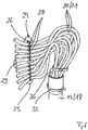
- Fig. 7 shows such a wire bundle interceptor 24 in isolation.
- a core bundle interceptor 24 In the area of a wire bundle interceptor 24, the respective core bundles 20 and 21 of the main cables 17 and 18 can be intercepted one above the other or side by side, wherein a core bundle interceptor 24 has a particular plate-shaped base body 25.
- a plurality of recesses 26 are introduced, which are positioned in a row and spread over the width of the plate-shaped body. Between two adjacent recesses 26 material webs 27 are formed.
- the core bundles 20, 21 are catchable on the respective core bundle interceptor 24 in such a way that cable ties 28 can be guided through the cutouts 26 while wrapping around the core bundles 20, 21.
- a wire bundle 20 or 21 intercepted using a cable tie 28 on a bundle wire catcher 24 abuts against the material web 27, which is located between the cutouts 26, through which the respective cable tie 28 is guided.
- each wire bundle interceptor 24 all wire bundles 20, 21 of the respective main cable 17 and 18 can be intercepted, in such a way that the wire bundles 20, 21 of the respective main cable 17, 18 are all positioned one above the other or next to each other.
- Each of the wire bundle interceptors 24, together with the bundles of cores 20, 21 intercepted thereon, can be detachably fastened to a side wall of the receiving device 13 of the distributor block 12, the plate-shaped main body 25 of the respective bundle interceptor 24 extending approximately parallel to the corresponding side wall of the receiving device 13.
- the plate-shaped base body 25 of the same are on the respective side wall of the receiving device 13 in a flat manner.
- the relative position of the wire bundle interceptors 24 on the side walls of the receiving device 13 is defined by a recess 29 of the plate-shaped base body 25 through which a helical projection of the respective side wall of the receiving device 13 extends in the assembled state, so as to secure the respective wire bundle interceptor 24 using a nut 41 releasably attach to the respective side wall of the receiving device 13.
- a core bundle interceptor 24 is thus fastened to both opposite side walls of the receiving device 13 of the distributor block 11, wherein all LINE core bundles 20 of the LINE main cable 17 and at a second core bundle interceptor 24 all VOICE core bundles 21 of the VOICE on a core bundle interceptor 24 Main cable 18 are catchable.
- FIGS. 9 and 10 show alternative embodiments of wire bundle interception devices 42, 43 for intercepting the LINE core bundles 20 of the LINE main cable 17 and the VOICE core bundles 21 of the VOICE main cable 18.
- the wire bundle interceptor 42 of the Fig. 9 as well as the wire bundle interceptor 24 of Fig. 1 to 8 a base body 25, in which a plurality of recesses 26 are introduced, wherein the recesses 26 are positioned in a row and spread over the width of the main body 25.
- a material web 27 is formed, against which a bundle of fibers to be intercepted abuts in the intercepted state.
- cable ties can be guided through the recesses 26 while looping around the respective wire bundles and while looping around the respective material web 27, which has a slightly smaller height than the wire bundles to be intercepted.
- the wire bundle interceptor 42 is in turn so releasably attachable to a side wall of the receiving device 13, that the base body 25 extends approximately parallel to a side wall of the receiving device and rests flat against the respective side wall of the receiving device.
- the statements on the wire bundle interceptor 24 of Fig. 1 to 8 refer.
- the wire bundle interceptor 43 of Fig. 10 has a base body 25 which extends approximately parallel to a side wall of the receiving device of the distributor block.
- recesses 45 for intercepting and guiding the wire bundle introduced in relation to the base body 25 by approximately 90 ° angled portions 44.
- the wire bundle interceptor 43 of the Fig. 10 has in the region of the base body 25 adjacent to the recess 29, which defines the relative position of the wire bundle interceptors 43 on the side walls of the receiving device 13, via the recesses 26 through which cable ties are feasible. With each cable tie can simultaneously several, here four, bundles of fibers, which are inserted into the recesses 45 of the sections 44, intercepted.
- the main body 25 lies flat against the respective side wall of the receiving device, or the sections 44 abut with their ends against the side wall of the receiving device.
- the data signal lines extending in the intercepted wire bundles can be fed to the connection elements 16 of the functional elements 15 via the wire guide channels of the wire guide elements 14 which open on the corresponding side wall, in order to be connected to the same.
- the sections of the data signal lines extending in the intercepted wire bundles extending between the wire bundle interceptor and the wire guide elements can be guided on a guide device 30 assigned to the respective side wall.
- the guide device 30 for the data signal lines has a plurality of threading sections 31, wherein the respective data signal lines can be threaded into the threading sections 31 of the respective guide device 30 after intercepting the respective wire bundles at the respective wire bundle interceptor and after connecting them to the connection elements 16 of the functional elements 15.
- a main cable interception device 32 which in Fig. 8 is shown in solo representation.
- the main cable interception device 32 has two interception sections 33, which are connected to one another via a transverse web 34.
- Fig. 5 can be removed, at each of the interception sections 33 of the main cable interception device 32 a main cable can be intercepted, namely on the one hand, the LINE main cable 17 and on the other hand, the VOICE main cable 18. So shows Fig. 5 in that the main cables 17, 18 can be intercepted at the respective intercepting section 33 using a cable tie 35.
- a cable sheath terminal 36 which is contacted in the region of each main cable 17, 18 on the one hand with the respective main cable 17, 18 and on the other hand with the respective intercepting section 33 of the main cable interception device 32, causes a shielding of the respective main cable 17, 18th
- the main cable interception device 32 has adjoining the interception sections 33, relative to the same by about 90 ° angled mounting portions 37, via which the main cable interception device 32 by means of screws 38 releasably fastened to the struts 12 of the distribution frame 10. Furthermore, the main cable interception device 32 has in the region of each attachment portion 37 via hooking portions 39 (see Fig. 8 ), wherein a distribution block 10 via its receiving device 13 in the attached to the struts 12 main cable interception device 32, namely in the Einhticianabbalde 39, can be suspended.
- a distribution block 11 suspended in the hooking-in sections 39 of the main cable interception device 32 can be detachably connected to the distributor frame 10 via screws 40 or can be fastened thereto.
- a respective intercepting portion 33 of the main cable interceptor 32 is positioned in a lower portion of a rear wall of the receiving device 13 of the distribution block 11 adjacent to both side walls thereof.
- the distributor block of the exemplary embodiment proceeds in such a way that firstly the main cable interception device 32 is detachably fastened to the distributor frame 10, namely to its struts 12. Serve this purpose, as already mentioned, the screws 38 which extend through the mounting portions 37 of the main cable interception device 32.
- the main cables 17, 18 are intercepted by means of cable ties 35 at the intercepting portions 33 of the main cable interception device 32.
- the loose tubes 20, 21 of the intercepted main cable 17, 18 are intercepted at a respective Aderbündelabfang worn 24, in which case the state according to Fig. 4 and 5 is reached.
- the data signal lines of the two main cables 17, 18 running in the intercepted wire bundles 20, 21 are fed via the corresponding wire guide channels of the wire guide elements 14 to the connection elements 16 of the functional elements 15 formed as IDC contacts and connected to the same, then the wire bundle interceptor 24 on the side walls the receiving device 13 of the manifold block 11 are attached.
- the distribution block 11 is suspended with the data signal lines connected to the connecting elements 16 and the core bundle interception devices attached to the side walls of the receiving device 13 in the main cable interceptor 32 and releasably secured to the distribution frame 10, namely on the struts 12, using the screws 40. Subsequently, the data signal lines can still be threaded into the threading sections 31 of the guide devices 30.
- the wire bundles 20, 21 of the main cables 17, 18 extend between the intercepting portions 33 of the main cable interceptor 32 and the respective wire bundle interceptor 24 with some excess length that can be used to remove a manifold block 11 from the manifold frame for servicing purposes 10 to disassemble, hang out of the main interception device 32 and pull out while maintaining the connection of the data signal lines to the formed as IDC contacts connecting elements 16 of the functional elements 15 forward from the distribution frame 10.
Landscapes
- Engineering & Computer Science (AREA)
- Computer Networks & Wireless Communication (AREA)
- Structure Of Telephone Exchanges (AREA)
- Installation Of Indoor Wiring (AREA)
Claims (11)
- Dispositif de répartition, plus précisément, bloc répartiteur, d'une installation de télécommunication, comprenant un dispositif d'accueil notamment réalisé sous la forme d'un bac d'accueil, dans lequel le dispositif d'accueil reçoit plusieurs éléments fonctionnels et plusieurs éléments de guidage de conducteur, dans lequel les éléments fonctionnels comportent notamment des éléments de raccordement réalisés sous la forme de contacts IDC pour le raccordement de lignes de signaux de données, et dans lequel les lignes de signaux de données rassemblées en faisceaux de conducteurs d'au moins un câble principal peuvent être acheminées vers les éléments de raccordement de manière à ce que les lignes de signaux de données puissent être raccordées aux éléments de raccordement des éléments fonctionnels, caractérisé par au moins un dispositif d'interception de faisceau de conducteurs (24 ; 42 ; 43), dans lequel plusieurs faisceaux de conducteurs (20, 21) d'un câble principal (17, 18) peuvent être interceptés l'un sur l'autre ou côte à côte au niveau du ou de chaque dispositif d'interception de faisceau de conducteurs, dans lequel le ou chaque dispositif d'interception de faisceau de conducteurs (24 ; 42 ; 43) comporte un corps de base (25) et dans lequel le ou chaque dispositif d'interception de faisceau de conducteurs (24 ; 42 ; 43) peut être fixé de manière amovible à une paroi latérale du dispositif d'accueil (13) de manière à ce que le corps de base (25) s'étende sensiblement parallèlement à une paroi latérale du dispositif d'accueil.
- Dispositif de répartition selon la revendication 1, caractérisé en ce qu'un dispositif d'interception de faisceau de conducteurs (24 ; 42 ; 43) peut respectivement être fixé aux deux parois latérales mutuellement opposées du dispositif d'accueil (13) afin d'intercepter, au niveau du dispositif d'interception de faisceau de conducteurs (24 ; 42 ; 43) respectif, tous les faisceaux de conducteurs (20, 21) du câble principal (17, 18) dont les lignes de signaux de données peuvent être acheminées, par l'intermédiaire de canaux de guidage de conducteurs débouchant sur ladite paroi latérale des éléments de guidage de conducteurs (14), vers les éléments de raccordement (16) des éléments fonctionnels (15).
- Dispositif de répartition selon la revendication 1 ou 2, caractérisé en ce que le corps de base (25) du ou de chaque dispositif d'interception de faisceau de conducteurs (24 ; 42 ; 43) est disposé, dans un état fixé au dispositif d'accueil, de manière à affleurer à la paroi latérale respective du dispositif d'accueil.
- Dispositif de répartition selon l'une ou plusieurs des revendications 1 à 3, caractérisé en ce que le dispositif d'interception de faisceau de conducteurs (24 ; 42 ; 43) présente plusieurs évidements (26) à travers lesquels le faisceau de conducteurs peut être guidé par enveloppement par un même serre-câble à des fins d'interception du faisceau de conducteurs.
- Dispositif de répartition selon l'une ou plusieurs des revendications 1 à 4, caractérisé par un dispositif d'interception de câble principal (32) au niveau duquel au moins un câble principal (17, 18) peut être intercepté.
- Dispositif de répartition selon la revendication 5, caractérisé en ce que le dispositif d'interception de câble principal (32) comporte deux sections d'interception (33) respectivement destinées à un câble principal (17, 18) et vient en prise avec le dispositif d'accueil de manière à ce que, dans une région inférieure d'une paroi arrière du dispositif d'accueil, une section d'interception (33) du dispositif d'interception de câble principal (32) soit positionnée au voisinage de ses deux parois latérales pour intercepter un câble principal respectif.
- Dispositif de répartition selon la revendication 5 ou 6, caractérisé en ce que le dispositif d'interception de câble principal (32) peut être fixé de manière amovible à un châssis de répartition par l'intermédiaire de vis, en ce que le dispositif d'interception de câble principal comporte des sections d'accrochage (39) pour le dispositif d'accueil afin d'accrocher le dispositif d'accueil de manière amovible dans le dispositif d'interception de câble principal fixé au châssis de répartition, et en ce que le dispositif d'accueil accroché dans le dispositif d'interception de câble principal peut être fixé de manière amovible au châssis de répartition, notamment par l'intermédiaire de vis.
- Dispositif de répartition selon l'une ou plusieurs des revendications 1 à 7, caractérisé en ce qu'un dispositif de guidage (30) respectif vient en prise avec les deux parois latérales opposées l'une à l'autre du dispositif d'accueil (13) pour les lignes de signaux de données des faisceaux de conducteurs qui sont interceptés dans la région de la paroi latérale respective au niveau du dispositif d'interception de faisceau de conducteurs (24) qui est associé à ladite paroi latérale, dans lequel chaque dispositif de guidage (30) comporte plusieurs sections d'enfilage (31), de manière à ce que les lignes de signaux de données puissent être enfilées, après l'interception du faisceau de conducteurs respectif sur le dispositif d'interception de faisceau de conducteurs respectif, après le raccordement de celui-ci à des éléments de raccordement des éléments fonctionnels dans la section d'enfilage du dispositif de guidage respectif.
- Dispositif de répartition selon l'une ou plusieurs des revendications 1 à 8, caractérisé en ce quea) le dispositif d'interception de câble principal peut être fixé de manière amovible à un châssis de répartition ;b) ledit ou chaque câble principal peut être intercepté sur l'une des sections d'interception du dispositif d'interception de câble principal ;c) les faisceaux de conducteurs du ou de chaque câble principal intercepté peuvent ensuite être interceptés sur un dispositif d'interception de faisceau de conducteurs respectif ;d) les lignes de signaux de données du faisceau de conducteurs interceptés dudit ou de chaque câble principal peuvent être acheminées, par l'intermédiaire de canaux de guidage de conducteurs des éléments de guidage de conducteurs, vers des éléments de raccordement des éléments fonctionnels d'un dispositif de répartition, et peuvent être raccordés à celui-ci, dans lequel le ou chaque dispositif d'interception de faisceau de conducteurs peut ensuite être fixé au dispositif de répartition ;e) le dispositif de répartition peut ensuite être accroché dans le dispositif d'interception de câble principal avec les lignes de signaux de données raccordées aux éléments de raccordement et peut être fixé de manière amovible au châssis de répartition.
- Dispositif de répartition, plus précisément, bloc répartiteur, d'une installation de télécommunication, comprenant un dispositif d'accueil, dans lequel le dispositif d'accueil reçoit plusieurs éléments fonctionnels, plusieurs dispositifs séparateurs xDSL coopérant avec les éléments fonctionnels et plusieurs éléments de guidage de conducteurs, dans lequel les éléments fonctionnels comportent des éléments de raccordement, dans lequel il est possible de raccorder aux éléments de raccordement, des lignes de signaux de données LINE rassemblées en des faisceaux de conducteurs qui sont utilisés pour la transmission de signaux de données vocales-données de calculateur combinés, d'un câble principal LINE, et des lignes de signaux de données VOICE rassemblées en des faisceaux de conducteurs qui sont utilisés exclusivement pour la transmission de signaux de données vocales à basse fréquence, d'un câble principal VOICE, dans lequel des éléments connecteurs sont associés au dispositif d'accueil, plusieurs câbles principaux de DSLAM peuvent être raccordés aux lignes de signaux de données DSLAM, qui sont exclusivement utilisées pour la transmission de signaux de données de calculateur à haute fréquence, et dans lequel des signaux de données vocales - de données de calculateur combinés peuvent être séparés par l'intermédiaire des dispositifs séparateurs xDSL en des signaux de données vocales et en des signaux de données de calculateur, et les signaux de données vocales et les signaux de données de calculateur peuvent être réunis en des signaux de données vocales - de données de calculateur combinés, caractérisé en ce qu'à chaque paroi latérale du dispositif d'accueil est associé un dispositif d'interception de faisceau de conducteurs respectif (24 ; 42 ; 43), dans lequel plusieurs faisceaux de conducteurs (20) du câble principal LINE (17) peuvent être interceptés les uns sur les autres ou côte à côte sur le dispositif d'interception de faisceau de conducteurs (24 ; 42 ; 43) associé à une première paroi latérale, et dans lequel plusieurs faisceaux de conducteurs (21) du câble principal VOICE (18) peuvent être interceptés les uns sur les autres ou côte à côte sur le dispositif d'interception de faisceau de conducteurs (24 ; 42 ; 43) associé à une seconde paroi latérale, et dans lequel chaque dispositif d'interception de faisceau de conducteurs (24 ; 42 ; 43) comporte un corps de base (25), et dans lequel chaque dispositif d'interception de faisceau de conducteurs (24 ; 42 ; 43) peut être fixé de manière amovible à la paroi latérale respective de manière à ce que le corps de base (25) s'étende sensiblement parallèlement à une paroi latérale du dispositif d'accueil (13).
- Dispositif de répartition selon la revendication 10, caractérisé par les éléments caractéristiques d'une ou plusieurs des revendications 2 à 9.
Applications Claiming Priority (2)
| Application Number | Priority Date | Filing Date | Title |
|---|---|---|---|
| DE200720001344 DE202007001344U1 (de) | 2007-01-24 | 2007-01-24 | Verteilereinrichtung einer Telekommunikationsanlage |
| PCT/EP2008/000008 WO2008089878A1 (fr) | 2007-01-24 | 2008-01-03 | Dispositif de répartition d'une installation de télécommunication |
Publications (2)
| Publication Number | Publication Date |
|---|---|
| EP2074834A1 EP2074834A1 (fr) | 2009-07-01 |
| EP2074834B1 true EP2074834B1 (fr) | 2017-03-15 |
Family
ID=37950474
Family Applications (1)
| Application Number | Title | Priority Date | Filing Date |
|---|---|---|---|
| EP08700966.8A Not-in-force EP2074834B1 (fr) | 2007-01-24 | 2008-01-03 | Dispositif de répartition d'une installation de télécommunication |
Country Status (3)
| Country | Link |
|---|---|
| EP (1) | EP2074834B1 (fr) |
| DE (1) | DE202007001344U1 (fr) |
| WO (1) | WO2008089878A1 (fr) |
Family Cites Families (2)
| Publication number | Priority date | Publication date | Assignee | Title |
|---|---|---|---|---|
| EP0766482A3 (fr) * | 1995-09-29 | 2000-02-02 | KRONE Aktiengesellschaft | Dispositif de distribution pour la technique de télécommuication et de données |
| DE10029870A1 (de) * | 2000-06-16 | 2002-01-03 | Rxs Kabelgarnituren Gmbh & Co | Verteilereinrichtung einer Datensignal-Verarbeitungsanlage und Datensignal-Verarbeitungsanlage |
-
2007
- 2007-01-24 DE DE200720001344 patent/DE202007001344U1/de not_active Expired - Lifetime
-
2008
- 2008-01-03 EP EP08700966.8A patent/EP2074834B1/fr not_active Not-in-force
- 2008-01-03 WO PCT/EP2008/000008 patent/WO2008089878A1/fr not_active Ceased
Non-Patent Citations (1)
| Title |
|---|
| None * |
Also Published As
| Publication number | Publication date |
|---|---|
| DE202007001344U1 (de) | 2007-04-05 |
| EP2074834A1 (fr) | 2009-07-01 |
| WO2008089878A1 (fr) | 2008-07-31 |
Similar Documents
| Publication | Publication Date | Title |
|---|---|---|
| EP1656720B1 (fr) | Dispositif de reception pour cables optiques et manchon de cable | |
| DE69730590T2 (de) | Rangierverbinder | |
| DE10317620B4 (de) | Glasfaser-Kopplermodul | |
| EP1290901B1 (fr) | Dispositif de distribution d'une installation de traitement de signaux de donnees et installation de traitement de signaux de donnees | |
| DE3347621A1 (de) | Verteilergestell fuer glasfaser-kabelenden | |
| EP2174174A1 (fr) | Système constitué de plusieurs dispositifs répartiteurs de fibres optiques | |
| EP0364658A2 (fr) | Dispositif de répartition, en particulier pour répartiteur principal de centraux téléphoniques | |
| WO2009007001A1 (fr) | Module de raccordement pour le domaine des télécommunications et données | |
| DE102007032579B4 (de) | Endverschluss für die Telekommunikations- und Datentechnik | |
| DE102007010854B4 (de) | Konsole für eine Verteilereinrichtung für Lichtwellenleiter-Kabel | |
| EP2074834B1 (fr) | Dispositif de répartition d'une installation de télécommunication | |
| DE202007005870U1 (de) | Vorrichtung zur Aufnahme von Steckverbindungen | |
| DE102007032577B4 (de) | Endverschluss für die Telekommunikations- und Datentechnik | |
| CH681668A5 (fr) | ||
| DE202013001434U1 (de) | Vorrichtung zur horizontalen Führung von Lichtwellenleiterkabeln und zur horizontalen Ablage von Überlängen der Lichtwellenleiterkabel | |
| DE202006017299U1 (de) | Zugabfangvorrichtung einer Lichtwellenleiterverteilereinrichtung | |
| EP4606006B1 (fr) | Traversée de ligne, utilisation d'une traversée de ligne et procédé de montage d'une traversée de ligne | |
| DE10019452A1 (de) | Patchpanel und Patchpanel-Anordnung | |
| EP2057717B1 (fr) | Dispositif de répartition d'une installation de télécommunication, dispositif de réception d'un tel dispositif de répartition ainsi que fiche de connexion | |
| DE102018102176A1 (de) | Splitter, Verbindungsmodul mit Splitter sowie Kabelverzweiger und Verwendung eines Splitters | |
| EP4286908A1 (fr) | Dispositif de maintien permettant de maintenir des conduites en fibre de verre | |
| DE202006017297U1 (de) | Lichtwellenleiterverteilereinrichtung | |
| DE29807669U1 (de) | Montagewanne für einen Endverschluß | |
| DE202006002084U1 (de) | Schirmungsvorrichtung für Verteilerblöcke | |
| DE9204909U1 (de) | Kabelhalter |
Legal Events
| Date | Code | Title | Description |
|---|---|---|---|
| PUAI | Public reference made under article 153(3) epc to a published international application that has entered the european phase |
Free format text: ORIGINAL CODE: 0009012 |
|
| 17P | Request for examination filed |
Effective date: 20090326 |
|
| AK | Designated contracting states |
Kind code of ref document: A1 Designated state(s): DE FR GB |
|
| DAX | Request for extension of the european patent (deleted) | ||
| GRAP | Despatch of communication of intention to grant a patent |
Free format text: ORIGINAL CODE: EPIDOSNIGR1 |
|
| INTG | Intention to grant announced |
Effective date: 20160912 |
|
| GRAS | Grant fee paid |
Free format text: ORIGINAL CODE: EPIDOSNIGR3 |
|
| GRAA | (expected) grant |
Free format text: ORIGINAL CODE: 0009210 |
|
| AK | Designated contracting states |
Kind code of ref document: B1 Designated state(s): DE FR GB |
|
| REG | Reference to a national code |
Ref country code: GB Ref legal event code: FG4D Free format text: NOT ENGLISH |
|
| REG | Reference to a national code |
Ref country code: DE Ref legal event code: R096 Ref document number: 502008015120 Country of ref document: DE |
|
| REG | Reference to a national code |
Ref country code: DE Ref legal event code: R097 Ref document number: 502008015120 Country of ref document: DE |
|
| PLBE | No opposition filed within time limit |
Free format text: ORIGINAL CODE: 0009261 |
|
| STAA | Information on the status of an ep patent application or granted ep patent |
Free format text: STATUS: NO OPPOSITION FILED WITHIN TIME LIMIT |
|
| 26N | No opposition filed |
Effective date: 20171218 |
|
| REG | Reference to a national code |
Ref country code: DE Ref legal event code: R119 Ref document number: 502008015120 Country of ref document: DE |
|
| GBPC | Gb: european patent ceased through non-payment of renewal fee |
Effective date: 20180103 |
|
| PG25 | Lapsed in a contracting state [announced via postgrant information from national office to epo] |
Ref country code: FR Free format text: LAPSE BECAUSE OF NON-PAYMENT OF DUE FEES Effective date: 20180131 Ref country code: DE Free format text: LAPSE BECAUSE OF NON-PAYMENT OF DUE FEES Effective date: 20180801 |
|
| REG | Reference to a national code |
Ref country code: FR Ref legal event code: ST Effective date: 20180928 |
|
| PG25 | Lapsed in a contracting state [announced via postgrant information from national office to epo] |
Ref country code: GB Free format text: LAPSE BECAUSE OF NON-PAYMENT OF DUE FEES Effective date: 20180103 |